4-WAY DISPLAY PANELS INSTALLATION
1
2
3
4
5
6
7
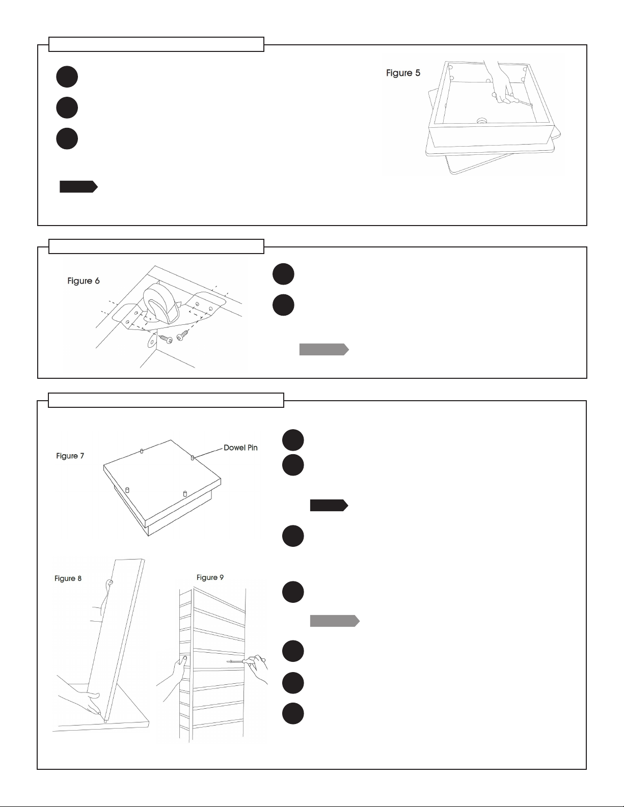
Flip the spinner base top so that the right side is up.
Insert (4) wooden dowel pins into the pre-drilled holes
on the base top and tap them into position with a
rubber mallet. (See Figure 7)
NOTE:
Two people are recommended for steps 3 through 5.
Install (2) panels onto the dowel pins so that they are
perpendicular to each other. Locate the holes on the
bottom of the panels and guide them onto the dowel
pins. (See Figure 8)
Attach the panels together by installing conrmat
screws into the pre-drilled holes using a #2 Phillips
screwdriver. (See Figure 9)
PRO TIP:
Do not fully tighten the screws until all the
panels are in place.
Install the remaining panels in the same manner to
complete the unit.
Once the wing panels are in place, tighten all screws
completely.
To conceal the screw heads, peel the decorative screw
cover caps to expose the sticky back, carefully center
over the screw heads, and press in place.
SPINNER BASE ASSEMBLY
CASTER INSTALLALTION (OPTIONAL)
Set the spinner base top on a protected surface. Make
sure the underside of the spinner base top is facing up.
Install the camlock pins into the pre-drilled holes of the
spinner base using the screwdriver. (See Figure 1)
Set the kick base onto the spinner base, aligning the
camlocks and camlock pins, and tighten the camlocks.
(See Figure 5)
NOTE: If you do not want the spinner base to rotate, install a screw through the bottom base panel into the top base
panel, taking care not to puncture through the surface of the top base panel. This will stabilize the spinner component
of the base unit.
1
2
Position the casters onto each of the four corners of the
kick base assembly. (See Figure 6)
Using (4) pan head screws per caster, attach the casters
through the pre-drilled holes on the inside corners of
the kick base. (See Figure 6)
PRO TIP: Install all screws before the nal tightening to allow
for easier alignment of casters.
1
2
3


