WEA 102 install 0510-UK ©WindowMaster 2009,2010 ®WindowMaster is a registered trademark used under license by WindowMaster Group
4. Mounting and connecting
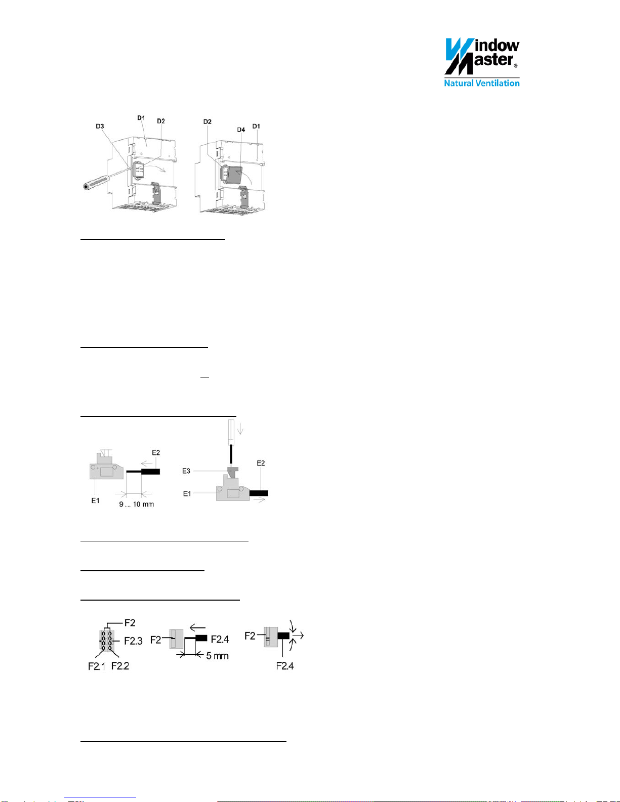
Picture 3
Connection to Bus without DIN-rain
If the connection to the Bus terminals is established without the use of a DIN-rail, the screening cap on the data rail
connection must be removed and replaced with the enclosed isolation cap, to ensure sufficient isolation from the DIN-rail.
Removal of cap: (picture 3)
On the back side of the power supply (D1) a cap (D3) is covering the connection contact (D2).
Insert a screwdriver between the power supply (D1) and the cap (D3) and remove the cap.
Mounting of isolation cap: (picuture 3)
Place the isolation cap (D4) on top of the contact system and press it down until it clicks.
Connection to bus with DIN-rail
WEA 102 is clicked onto the DIN-rail.
Ensure that the type shields on all the products placed on the DIN-rail are turning in the same direction (reading
direction), this will ensure that the polarization of the products are correct.
Free areas on the DIN-rail must be shielded / covered.
Connection of main voltage (picture 4)
Picture 4
Connection is carried out with the plug-in terminals (E1).
The wire (E2) is stripped ca. 9-10mm.
Disconnection of main voltage (picture 4)
With a screwdriver, press on the lock (E3) on the terminal and pull out the wire (E2) of the terminal (E1).
Installation of the bus terminal
Place the terminal in the guiding groove and press the terminal down to the stop.
Connection of bus terminals (picture 5)
Picture 5
- For terminal (F2) a 0,6…0,8mm² onewired conductor is used.
- Terminal F2 consists of a red (yellow) terminal (F2.1) and a black (white) terminal F2.2.
- Each terminal can be connected to up to 4 onewired of 0,6…0,8mm².
- Conductor F2.4 is stripped approx 5mm and inserted into terminal F2 (red/yellow = +, black/white = -).
Dismounting of the low current terminal (picture 5)
Pull the terminal F2 off and wriggle the BUS conductor F2.4 back and forth while pulling. 3