WindowMaster NV Solo User manual

UK +44 (0) 1536 510990 [email protected]
NV Solo® install+operating 1608-UK ©WindowMaster 2007, 2016 ®WindowMaster is a registered trademark used under licence by WindowMaster Group
NV Solo®
Control for one room / zone
Read instruction carefully before proceeding and keep for future reference (translated text).

2
Contents
1. Description.....................................................................................................................................................................3
1.1 Delivery .........................................................................................................................................................................3
1.2 Start-up..........................................................................................................................................................................3
1.3 Connection....................................................................................................................................................................3
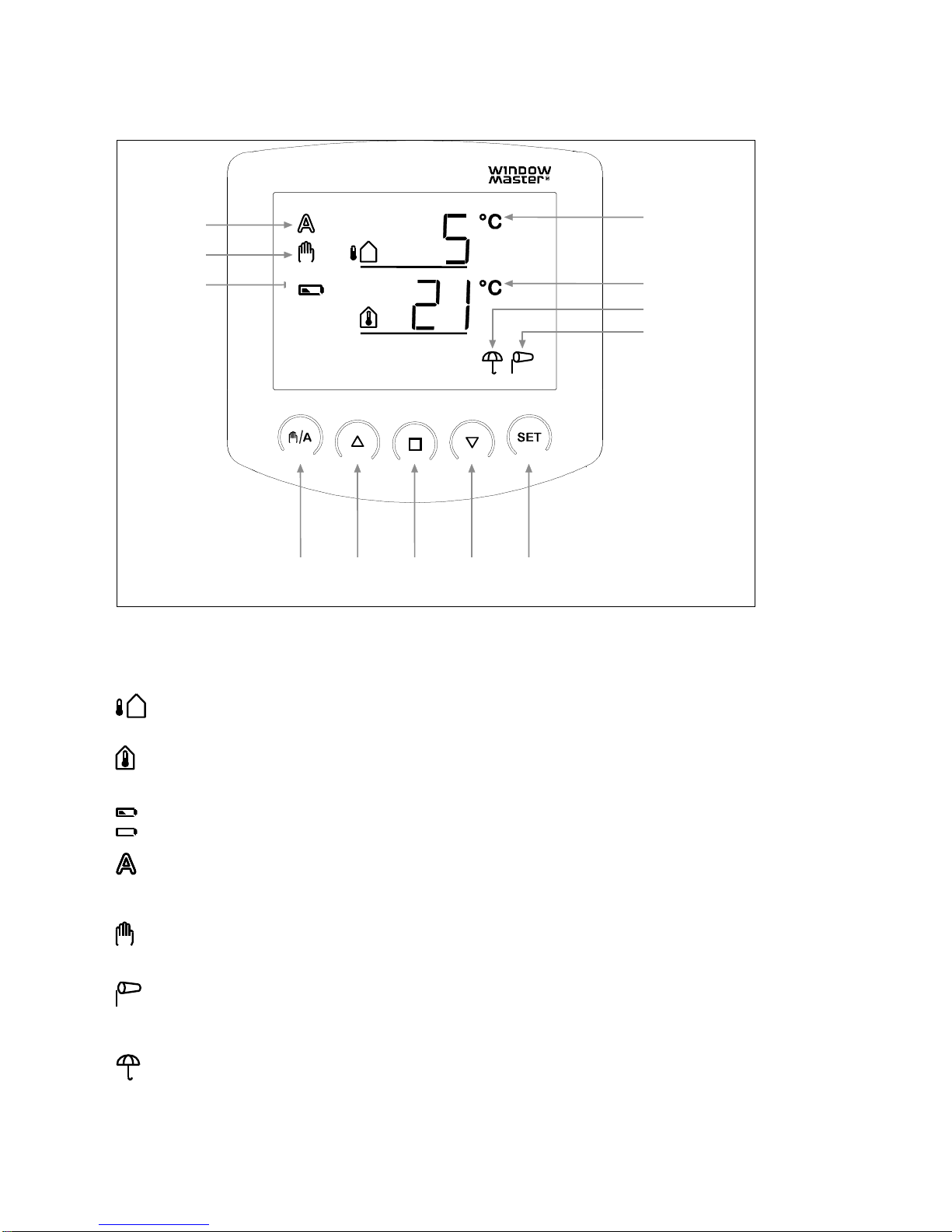
2. Control panel .................................................................................................................................................................4
2.1 Keys and symbols .........................................................................................................................................................4
2.2 Displaying wind speed...................................................................................................................................................5
2.3 Manual operation...........................................................................................................................................................5
3. Setting values for AUTOMATIC operation...................................................................................................................6
3.1 Indoor temperature........................................................................................................................................................7
3.2 Outdoor temperature lock-out........................................................................................................................................7
3.3 Wind alarm ....................................................................................................................................................................8
3.3.a Table: Wind speed......................................................................................................................................................9
3.4. Rain alarm....................................................................................................................................................................9
3.5 Save the values SAV...................................................................................................................................................10
4. Basic settings..............................................................................................................................................................11
4.1 Radio connection to the weather station......................................................................................................................12
4.2 Wind and rain alarm, temporary or permanent............................................................................................................13
4.3 dAS..............................................................................................................................................................................13
4.4 Operating setting LEAPOS or LEASP .........................................................................................................................14
4.4.A LEAPOS is selected.................................................................................................................................................15
4.4.C CLR is selected........................................................................................................................................................17
5. Safety information.......................................................................................................................................................18
6. Weather station............................................................................................................................................................19
6.1 Description ..................................................................................................................................................................19
6.2 Installation of the weather station................................................................................................................................19
6.2.1 Sensor......................................................................................................................................................................19
6.2.2 Holder.......................................................................................................................................................................20
6.3 Weather station mounting holes..................................................................................................................................20
6.4 Connecting the weather station...................................................................................................................................21
6.4.1 Printed circuit board..................................................................................................................................................21
6.4.2 Connecting power.....................................................................................................................................................21
7. Control panel ...............................................................................................................................................................23
7.1 Description ..................................................................................................................................................................23
7.2 Placement of the control panel....................................................................................................................................23
7.3 Mounting holes on the control panel............................................................................................................................23
7.4 Radio signal.................................................................................................................................................................23
7.5 Start-up ER..................................................................................................................................................................24
7.6 Testing sensors...........................................................................................................................................................25
7.6.1 Wind sensor .............................................................................................................................................................25
7.6.2 Rain sensor..............................................................................................................................................................25
7.6.3 Temperature sensor.................................................................................................................................................25
8. Maintenance.................................................................................................................................................................25
8.1 Weather station ...........................................................................................................................................................25
8.2 Control panel...............................................................................................................................................................25
8.2.1 Batteries...................................................................................................................................................................25
9. Error messages ...........................................................................................................................................................26
9.1 Retrieving service data................................................................................................................................................27
10. Technical data............................................................................................................................................................27
10.1 Control panel.............................................................................................................................................................27
10.2 Weather station .........................................................................................................................................................27
10.3 Factory settings.........................................................................................................................................................27
10.4 Personal setting data for AUTOMATIC operation......................................................................................................28
10.5 Examples of structures..............................................................................................................................................28
10.6 Connection diagram for weather station....................................................................................................................29
10.6.1 WUC 102, WUC 160, WSC 304 and WSC 3x0 Standard.......................................................................................29
10.6.2 WCC 3x0 Standard.................................................................................................................................................30
10.6.3 WxC 3x0 Plus.........................................................................................................................................................31

3
1. Description
The NV Solo®weather station can automatically control opening and closing of windows in a room (a zone) in
order to achieve the desired indoor climate.
AUTOMATIC operation
Opens the window at the selected indoor temperature
Closes the window if the temperature falls below the selected outdoor temperature (outdoor temperature
lock-out)
Opens the window to the selected preset position (LEAPOS)
Or the window opens modulated (selected opening time (LEASP))
Closes the window at a selected wind speed (wind alarm, optional)
Closes the window if it rains (rain alarm, optional)
The window closes when the temperature falls below the set indoor temperature or if a rain or wind alarm is
registered.
MANUAL operation;
The windows are operated manually using the control panel.
The wind and rain alarm is active, if it has been activated under AUTOMATIC operation.
1.1 Delivery
NV Solo®is comprised of a weather station and a control panel with 2 x 1.5V AA/LR6 batteries.
1.2 Start-up
Installation, testing and start-up of the window motor and the control unit are performed in
compliance with applicable national legislation.
1. Setting values for basic settings (see point.4)
2. Setting values for automatic operation (see point.3)
3. Installation and connection (see points 6 & 7)
1.3 Connection
NV Solo®is connected to WindowMaster WUC or WCC control units by Natural Ventilation or WSC compact
smoke panels for fire ventilation.

4
2. Control panel
2.1 Keys and symbols
The control panel displays the control signals, outdoor and indoor temperatures, as well as rain or wind alarms.
It also displays the operational setting and battery status.
Weather data is updated every minute.
Outdoor temperature
Shows the current outdoor temperature.
Indoor temperature
Shows the current indoor temperature.
Battery symbol –half charged
Battery symbol - empty
AUTOMATIC operation
The window automatically opens and closes, as per the selected values for indoor and outdoor
temperatures, wind speed and rain.
MANUAL operation
The window motor is operated manually using the arrow keys.
Wind alarm
When the wind alarm is active, the window will close when wind speeds higher than the alarm
value are registered.
Rain alarm
When the rain alarm is active, the window will close if rain is registered.
Outdoor
temperature
Indoor
temperature
Rain alarm
Wind alarm
Manual/ Open STOP Close SET
automatic
Automatic
Manual
Evt. battery-
symbol

5
2.2 Displaying wind speed
When the display shows the temperature, briefly press the key once and the display will then change to
wind speed.
Briefly press the key again or wait approx. 60 seconds and the display will return to the temperature
display screen.
Wind speed can be displayed in both AUTOMATIC and MANUAL settings.
Note: The wind speed will not be displayed correctly for approx. 90 seconds after power has returned to the
weather station (e.g. after a loss of power or at start up). If the wind alarm is activated, manual operation is
blocked during this time.
2.3 Manual operation
The connected windows can be operated manually using the control panel keys.
AUTOMATIC operation is “switched off” and operation is no longer based on the indoor temperature.
The rain and wind alarms remain active if they are set to active in AUTOMATIC mode.
If the window is operated by using the (arrow keys), the system will revert back to AUTOMATIC operation
after 30 minutes.
If the key has been pressed for operating in (MANUAL operation), operation will remain in MANUAL
until the system has been returned to AUTOMATIC control by pressing the key.
Open stop close
The connected window can be operated manually using the , and (open, stop, close) keys.
With a short press of the key (shorter than 1 second), the window opens completely.
With a long press of the key (longer than 1 second) the window opens as long as the key is pressed.
With a short press of the key, the window closes completely.
With a long press of the key, the window closes as long as the key is pressed.
Pressing stops the window motor.
Manual/automatic
key switches between the AUTOMATIC and MANUAL operating modes. After manual operation
using the , or keys, the control system will be in MANUAL operating mode. Thus, AUTOMATIC
operation is deactivated and control is no longer based on the temperature. Pressing the key returns the
system to AUTOMATIC operating mode.

6
A long press of the key switches to the setting of values for AUTOMATIC operation and two long presses
switch to the setting of values in basic settings.
3. Setting values for AUTOMATIC operation
In order to achieve optimal ventilation, the values in AUTOMATIC operation must be adapted to the building
conditions.
Press the key on the control panel for at least 3 seconds to get to the programming of values for
AUTOMATIC operation.
When the two symbols and are shown on the left of the display, the values can be changed (points 3.1 to
3.5).
If the programming setting is exited by pressing the key or if the keys are not activated within 5 minutes, the
programming setting will be exited and the entered settings will not be saved.
Exit
Confirm /
continue
The control panel
is in AUTOMATIC
mode

7
3.1 Indoor temperature
The first parameter that can be set is the indoor temperature, i.e. the interior temperature at which the window
shall open. The indoor temperature is pre-programmed to 25°C.
If the interior temperature is greater than this value the window will open, unless the outdoor temperature is
lower than the set lock-out value (3.2) or a wind or rain alarm is registered (points 3.3 and 3.4).
The indoor temperature has a hysteresis of 2°C, meaning the window will close again as soon as the indoor
temperature drops with more than 2°C below the set temperature.
The indoor temperature symbol blinks.
The value is set using , or select (found at +41°C and +4°C)
If is selected, the system will not be controlled by temperature, which is why setting the exterior
temperature lock-out (3.2) is skipped. The window can be operated manually and the wind and rain alarms are
active if they have been set to active in AUTOMATIC operation (points. 3.3 and 3.4)
Confirm the selection by pressing the key. The display will automatically change to setup for the next
parameter –outdoor temperature lock-out (point 3.2).
3.2 Outdoor temperature lock-out
The second parameter that can be set is the outdoor temperature lock-out. It is preset to 5°C.
The outdoor temperature lock-out is the temperature at which the window shall close if the temperature outside
falls below the selected temperature. The lock-out shall also hold the window closed to prevent energy loss,
even if the indoor temperature is exceeded.
The hysteresis of the outdoor temperature lock-out is 2°C, meaning opening of the window is only enabled
when the outdoor temperature is more than 2°C above the set temperature.

8
When the outdoor temperature symbol blinks, the value can be set using the keys or by selecting
(found at +21°C and -21°C)
If is selected, the "Outdoor temperature lock-out" will be turned off.
Confirm the selection by pressing the key. The display will automatically change to setup for the next
parameter –wind alarm (point 3.3).
The outdoor temperature lock-out should be set to a temperature above 0°C, if possible. If a window is opened
while temperatures are below 0°C, frozen rubber seals can get damaged.
3.3 Wind alarm
The third parameter to be selected is whether the wind alarm shall be ON (active) or OFF (not active).
An active wind alarm prevents the window from being damaged. The wind alarm is factory pre-set to 4 m/s.
If an active wind alarm is selected, the window closes if the wind sensor registers wind speeds greater than the
set value.
The window can still be operated using , but will return to AUTOMATIC operation after 2 minutes.
Table 3.3 can be used as a guide to finding the optimal value.
A wind alarm is maintained for 5 minutes. If the set wind value is exceeded by a new value during these 5
minutes, the period will begin again.
As long as a wind alarm is registered, the windsock symbol will be shown on the display.
RECOMMENDED SETTING; ACTIVE
If a non-active wind alarm is selected, the window will not close despite the high wind speeds.
When the wind alarm symbol blinks, the value can be set using the keys or by selecting (found at
21 m/s and 0 m/s).
If is selected, the "Wind alarm” is not activated.
Confirm the selection by pressing the key. The display will automatically change to setup for the next
parameter –rain alarm (point 3.4).

9
3.3.a Table: Wind speed
Description
m/s
km/hour
Beaufort scale
Knots
Calm
< 0.3
< 1.1
0
< 1
Light air
0.3-1.5
1.1-5.4
1
1-3
Light breeze
1.6-3.3
5.5-11.9
2
4-6
Gentle breeze
3.4-5.4
12.0-19.4
3
7-10
Moderate breeze
5.5-7.9
19.5-28.4
4
11-16
Fresh breeze
8.0-10.7
28.5-38.5
5
17-21
Strong breeze
10.8-13.8
38.6-49.7
6
22-27
Near gale
13.9-17.1
49.8-61.5
7
28-33
Gale
17.2-20.7
61.6-74.5
8
34-40
Severe gale
20.8-24.4
74.6-87.8
9
41-47
Storm
24.5-28.4
87.9-102.2
10
48-55
Violent storm
28.5-32.6
102.3-117.3
11
56-63
Hurricane
> 32.6
> 117.3
12
> 63
3.4. Rain alarm
The fourth parameter that can be set is whether the rain alarm shall be active or not active .
An active rain alarm prevents water penetration. The rain alarm is pre-programmed to be active.
In active, the window closes if the rain sensor registers rain.
The window can still be operated using , but will return to AUTOMATIC operation after 2 minutes.
A rain alarm is maintained for 5 minutes. If precipitation is detected again during these 5 minutes, the period
starts over again.
As long as a rain alarm is registered, the umbrella symbol will be shown on the display.
RECOMMENDED SETTING; ACTIVE
If a non-active alarm is selected, the window will not close even if it rains.
When the rain alarm blinks, select whether the alarm shall be active ( ) or non-active ( )
Using , select between and .
Confirm the choice by pressing the key. The display will automatically change to setup for the next
parameter –save the values (point 3.5).

10
3.5 Save the values SAV
Once the values in points 3.1-3.4 have been set, save the values (SAV=save) by pressing the key, and the
display returns automatically to the indoor and outdoor temperatures.
If is pressed here, you will exit SAV without saving the values.

11
4. Basic settings
The basic settings are comprised of the radio connection to the weather station, operating settings for the wind
and rain alarms, and the operating position for the open function.
To change the basic settings, press the key for at least 3 seconds. The two symbols and will be
shown on the left side of the display.
Press the key again for at least 3 seconds. , CON and the antenna symbols will be shown in the
display. The basic settings can now be set.
If the programming setting is exited by pressing the key or if the keys are not activated within 5 minutes, the
programming setting will be exited and the entered settings will not be saved.
The operating
panel is in
MANUAL
mode
Exit
Switch
Confirm /
Continue

12
4.1 Radio connection to the weather station
The first parameter to be set-up is the radio connection between the control panel and the weather station.
The antenna blinks and the connection between the control panel and the weather station can be registered.
Press the key to select between LEA and CLR:
(Lea=registers) to register a radio connection to the weather station
(Clear=delete) to delete an existing radio connection
Confirm the choice by pressing the key.
If LEA is selected; the radio symbol will stop blinking and the radio waves will begin to "run”.
Press the orange programming key inside the weather station to establish the radio connection (see the photo
of the weather station interior in point 6.4.1.b).
The connection has been established when the LED (the little white square) that is mounted above the
programming key gives two short blinks. The display will automatically change to setup for the next parameter –
wind and rain alarm (point 4.2)
If CLR is selected; the radio connection is deleted. The display automatically changes to so that a new
connection can be established. Then follow “If LEA is selected”

13
4.2 Wind and rain alarm, temporary or permanent
The second basic setting to be set is for a temporary or permanent wind and rain alarm.
The signal from the wind or rain alarm can be temporary (the signal to the control unit stops after 4 minutes -
OFF) or permanent (continues as long as the rain sensor is wet or the wind sensor senses wind - ON).
The alarm is factory set to ON.
Select the desired setting ON or OFF using ;
The alarm signal shall be permanent (The window remains closed in the event of a rain or wind
alarm).
The control panel is factory set to ON. RECOMMENDED SETTING
The alarm signal shall stop after 4 minutes
Confirm selection by pressing -key. The display will automatically change to setup for the next parameter –
dAS (4.3).
4.3 dAS
The third basic setting to be set is dAS.
dAS is a function that makes it possible to use WindowMaster Smoke Ventilation Units WSC xxx.
dAS is pre-set to be ON.
RECOMMENDED SETTING: ON.
Confirm the selection by pressing the key. The display will automatically change to setup for the next
parameter –operating setting (point 4.4).

14
4.4 Operating setting LEAPOS or LEASP
NV Solo®has two different operating settings LEAPOS and LEASP.
The control panel is factory set to LEASP.
LEAPOS;
The window opens to the set opening position each time the window opens in AUTOMATIC operation.
The window closes when the temperature falls below the selected indoor temperature. The temperature is
registered every 4 minutes.
To set the opening position, see point 4.4.a.
To set the indoor temperature, see point 3.1
LEASP;
The window opens modulated, i.e. with a fixed run time, every time the window opens in AUTOMATIC
operation.
The temperature is recorded;
1. If the temperature is too high, the window will open. If the temperature has not fallen sufficiently the next time
the temperature is checked, the window is opened further with the fixed run time. This is repeated until the
desired indoor temperature is reached. This is however conditional on the maximum chain length of the window
motor not being exceeded.
2. If the temperature is too low and the window is open, the window will close modulated until the temperature
falls below the selected indoor temperature.
The run time is factory set to 5 seconds. To set the run time, see point 4.4.b.
The time interval for temperature registration is factory set to 7 minutes. To set the interval time, see point 4.4b
To set the indoor temperature, see point 3.1
is displayed and the clock blinks
Press the key to select between CON, LEAPOS, LEASP and CLR:
(Continue) to skip individual setting of the opening position, run time and control interval time.
NV Solo®will then use the factory set values.
POS (Learn POS=read position) to record the selected opening position
SP (Learn STEP=set interval) to set the run time and interval time
CLR (Clear) Deletes the values entered and uses the factory set values (run time 5 sec. / interval
time 7min.)
Confirm the choice by pressing the key.
If both LEAPOS and LEASP are set, the last set operational setting is followed.

15
4.4.A LEAPOS is selected
1. The display shows (CLS=close) and the clock blinks.
2. Close the window completely by holding down
3. When the window is completely closed, press the key. The display automatically changes to set up
for the next parameter–determining the fixed open position (OPN)
1. The display shows OPN and the clock blinks
2. Hold down (open) until the desired ”Fixed open position” is reached
3. Confirm the selection by pressing the key. The display will automatically change to setup for the next
parameter –SAV.
1. The display shows SAV (save).
2. Confirm the selection by pressing the key. The display will automatically change to display the indoor
and outdoor temperatures.
3. The system is operating in manual setting. Change if necessary to AUTOMATIC operation
Setting the basic settings can be exited by pressing and the changed settings will not be saved.

16
After the settings in the basic settings have been set and saved, the values for AUTOMATIC operation can be
adjusted. Test the sensor function the first time this function is used, (point 7.6).
4.4.B LEASP is selected
After confirmation of SP;
1. The display shows the run time “5 sec.” and the clock blinks.
2. Set the time using .
3. Confirm the selection by pressing the key. The display will automatically change to setup for the next
parameter –control-interval time
1. The display shows the control-interval time 7 min. and the clock blinks.
2. Set the time using
3. Confirm the selection by pressing the key. The display will automatically change to setup for the next
parameter –save ( )
1. The display shows SAV (save).
2. Press the key to save the entries. The display will change to display the indoor and outdoor
temperatures.
3. The system is operating in manual setting. Change if necessary to AUTOMATIC operation

17
If is pressed, the basic settings are exited and the changed values are not saved.
After the settings in the basic settings have been set and saved, the values for AUTOMATIC operation can be
adjusted. Test the sensor function the first time the function is used (point 7.6).
4.4.C CLR is selected
1. The display shows CLR (CLS=clear) and the clock blinks.
2. Confirm the selection by pressing the key. The display will automatically change to setup for the next
parameter –save ( )
1. The display shows (save).
2. Confirm the selection by pressing the key. The display will automatically change to display the
indoor and outdoor temperatures.
3. The system is operating in manual setting. Change if necessary to AUTOMATIC operation
4. In automatic operation, the window will now open/close per the factory set values, run time 5 sec. and
temperature check every 7 minutes.

18
5. Safety information
In the event of a power failure to the weather station, the control unit can no longer control the connected
window motor!
The settings that are stored in the control panel are saved in the event of a power failure.
When the power returns, the controls go into AUTOMATIC operation.
If the radio connection between the control panel and the weather station is interrupted (e.g. if there are
disturbances with the radio connection or because the batteries in the control panel are empty), the window
cannot be operated manually. The system continues in AUTOMATIC operation without regard for the indoor
temperature until the radio connection is re-established. The wind and rain protection functions are maintained
if they were set to active before the power failure.
If it begins to rain, it may take some time before the weather station sounds the alarm, depending on the
outdoor temperature and the amount of rainwater. Closure time shall also be added for electrically powered
windows. Therefore, objects that are sensitive to moisture should not be placed in the area as they can be
damaged if water flows in.
Note that the windows, e.g. in the event of a power failure, do not automatically close if there is a rain alarm
unless an emergency power system is connected.
Safety instructions
Make sure that the window is in suitable condition for electric operation. It is recommended to grease
window hinges at least once a year after installation of the motor unit.
ATTENTION! To avoid personal injury during installation, do not connect motor to power supply until
installation is complete.
Electrically operated windows may cause personal injury if body parts are caught within the operating area
of the window. Where there is a risk of personal injury or a situation where children are involved, it is
recommended that the operation mode where the motor will run only as long as the keypad button/switch is
pressed be set to manual. In the automatic mode, because of the tractive capacity of the system, the risk of
personal injury will be increased. Never leave children in charge of window operation.
NV Solo®is a 24 V DC product and must not be connected to the mains voltage, as it thereby will be
damaged.
NV Solo®should not be fitted to a window, which is used for emergency escape/access.
Make sure that mains voltage is disconnected when cleaning or other maintenance/service of the window is
being undertaken, and ensure that it cannot be unintentionally reconnected.
Window actuators for smoke ventilation: If the window actuator has been exposed to temperatures above
90 °C it has to be checked by a WindowMaster technician.
The packing can be disposed of together with ordinary household waste. The product must be disposed of
in conformity with national regulations for electronic waste and not with usual household waste.
In case of technical problems, please contact WindowMaster, see telephone list.

19
6. Weather station
6.1 Description
The weather station is supplied with power from a WUC / WCC control unit or from the WSC compact central.
It communicates with the weather station via a radio connection.
6.2 Installation of the weather station
6.2.1 Sensor
The sensor shall be mounted on the building so that the sensor can collect wind and rain unhindered. The
weather station must not be overshadowed by buildings, trees or similar. There must be a free area of at least
60cm below the weather station to allow for correct wind measurement and to avoid it being covered with snow.
There must be at least 60cm of space below, to the sides and
in front of the weather station left from other elements
(structures, construction parts etc.)
The weather station must be mounted on a vertical wall (or al
pole).
The weather station must be mounted in the horizontal
transverse direction (horizontally).
Horizontal
Wall
or
pole

20
6.2.2 Holder
The weather station includes a combined holder for wall/pole mounting. At delivery, the holder is mounted on
the sensor.
6.2.2.a Remove the holder using a screwdriver 6.2.2.b Push the holder downwards and out
When mounting vertically on the wall, place the flat side in toward the
wall with the half-moon shaped pin upward.
6.2.2.c
When mounting vertically on a pole, mount with the curved
side in toward the post and the pin downward
6.2.2.d
6.3 Weather station mounting holes
Pin
Oval hole 7,5 x 5 mm
Measures in mm
Pin
Table of contents
Other WindowMaster Weather Station manuals
Popular Weather Station manuals by other brands

Celestron
Celestron 47005 instruction manual

P3 International
P3 International E 9300 Specifications

National Geographic
National Geographic 265NC manual

La Crosse Technology
La Crosse Technology Tomorrow's Weather Today WS-7394U-IT instruction manual

Ambient Weather
Ambient Weather WS-1050 user manual

Balance Meteo
Balance Meteo 865373 user manual