1.5.3 WHAT IF THE BRACKET IS ALIGNED
INCORRECTLY?
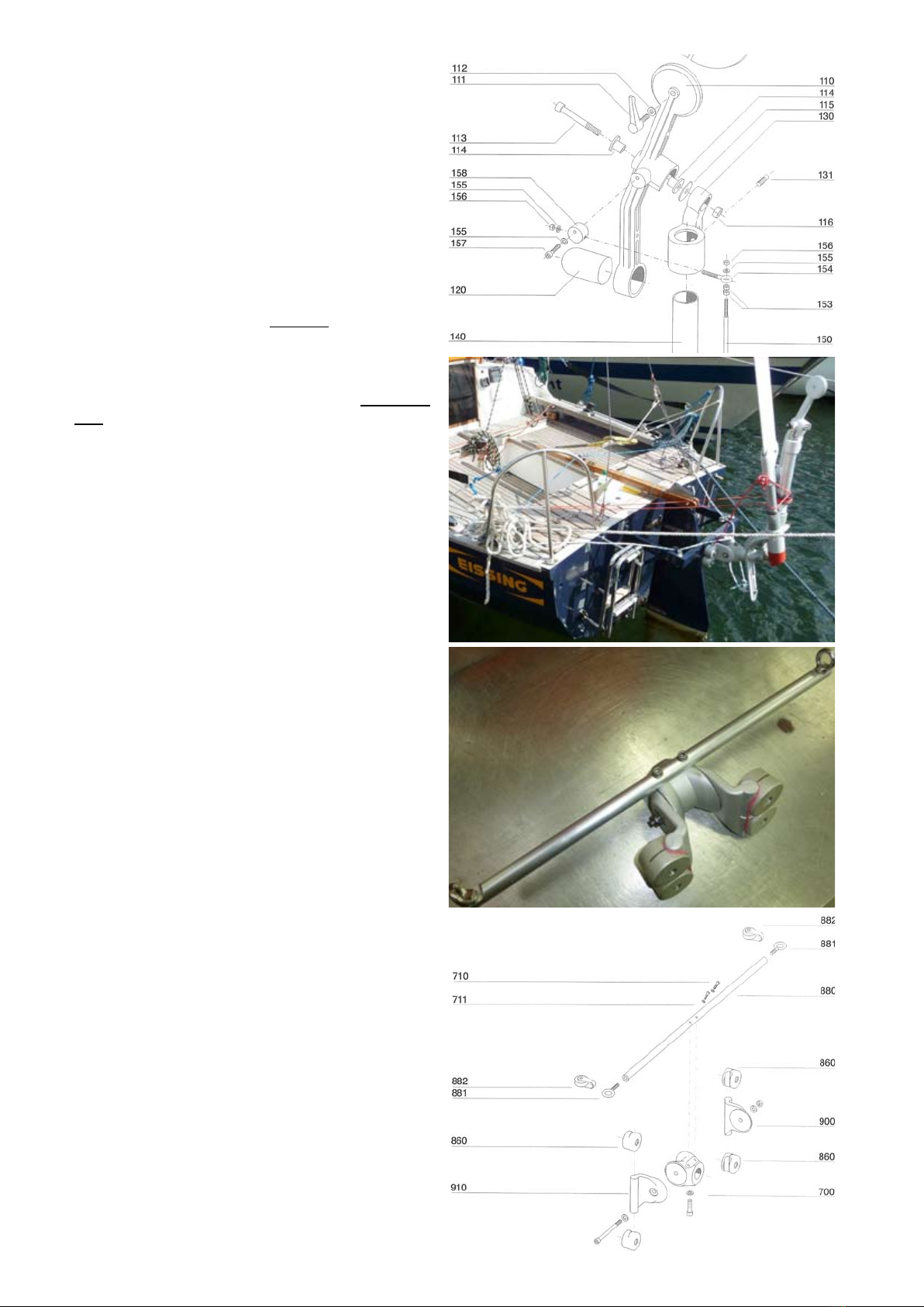
• Noproblem:loosenmountingbolts901andusethe
rubber mallet to move the clamps along the cheeks
900/910 until the alignment is satisfactory.
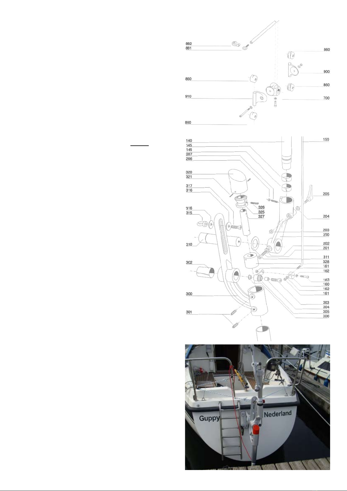
1.5.4 MOUNTING THE SYSTEM ON THE
MOUNTING BRACKET
• Slidethesystemintothebracketwiththependulum
axle 310 at the front and fasten in place with
mounting bolt 901.
1.5.5 ALIGNMENT
WINDVANE SHAFT 140
• Thewindvaneshaft140mustbevertical.
• Side-to-sideadjustment:releasebolt701
• Fore-and-aftadjustment:releasebolt201
• Don’tforgettoretightentheboltsoncethe
windvane is properly aligned!
• Ifyoustillcan’tmakethewindvanevertical,see
1.5.4 What if the Bracket is Aligned Incorrectly?
1.5.6 PENDULUM RUDDER LIFT-UP
• Tieoneendoftheredlift-uplinethroughring431
and secure the other end to the pushpit. Raise the
pendulum rudder, take the red line once around
windvane shaft 140 and rudder shaft 400 and tie it
back to the pushpit.
1.6 THE STEERING LINES
1.6.1 GENERAL
• ThesteeringperformanceofyourPACIFICLIGHT
will be strongly influenced by the quality of the
force transmission from the pendulum rudder to
the main rudder; in other words, you can’t have
good steering unless the steering lines are working
smoothly.
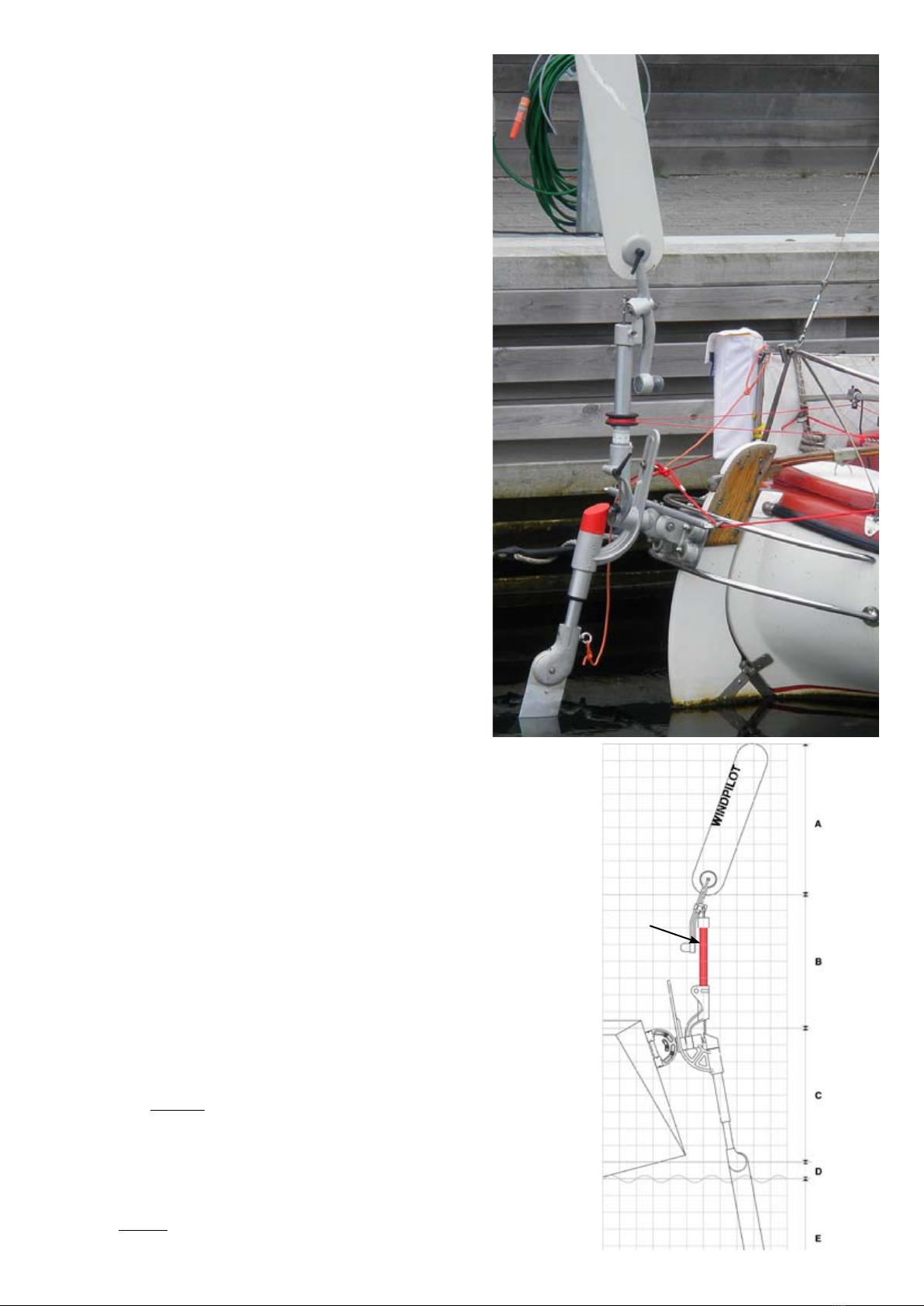
• Dependingonthesettingofthevariable
transmission, the PACIFIC LIGHT provides
maximum steering line travel of between 20 and
25 cm/8 and 10 in (a feature it shares with other
popular systems like the Aries and Monitor).
• Anythingthatimpairstheforcetransmissionwill
have an immediate impact on steering quality.
Slack, stretch or play in the steering lines or
stiffness in the main rudder bearings all detract
from the performance of your system. Errors and
compromises at this point add up to poor steering,
plain and simple. All servo-pendulum gears that use
the 2:1 bevel gear linkage (Aries, Fleming, Monitor)
work in exactly the same way. The differences lie in
the operating conditions on different boats!
• NOTE:whatuseis20-25cm/8-10inoftravelatthe
pendulum arm if only a fraction of that reaches the
main rudder?