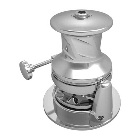
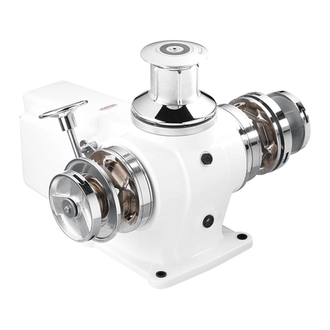
Lofrans GECKO User manual

INSTALLATION AND USER’S MANUAL
GECKO Stern Windlass
ALU 12V only Rope
GECKO Stern Windlass
ALU 12V only Rope
Via Philips, 5 - 20052 Monza (MB) (Italy)
STORE THIS MANUAL ON BOARD
Lofrans'

Dear Customer,
Thank you for choosing a Lofrans' product. Lofrans' is a leader company in the production and worldwide distribution
of nautical systems manufactured according to the most modern technologies, in compliance with international
regulation requirements and the most important certifying bodies. All of our products are manufactured with excellent
materials suited for operations in marine environments and are subject to continuous checks to improve the
qualitative levels and make them without any manufacturing defects. Together with such requirements, Lofrans'
anchor windlasses are a synthesis of reliability and efficiency, by guaranteeing the maximum performances during
each phase of mooring, even in the most difficult. With a Lofrans' product, years of reliable operations are guaranteed.
Lofrans©copyright, 2022. All rights reserved.
Lofrans' declines any liability for possible inaccuracies due to print errors in this manual and reserves the right to
introduce any changes deemed appropriate.
For this reason, Lofrans' does not guarantee the accuracy of the manual after the date of issue and declines all liability
for possible errors and omissions.
Contents
1. INTRODUCTION............................................................................................................................................................. 4
1.1 Purpose of the Manual ........................................................................................................................................... 4
1.2 Assistance................................................................................................................................................................ 4
1.3 Receipt and Storage................................................................................................................................................4
2. SAFETY INFORMATION..................................................................................................................................................5
3. INSTALLATION ...............................................................................................................................................................6
3.1 Contents of Package................................................................................................................................................ 6
3.2 Equipment Necessary for Installation.....................................................................................................................6
3.3 Recommended Accessories ....................................................................................................................................6
3.4 General Requirements for installation.................................................................................................................... 6
3.5 Prevention from Electrolysis...................................................................................................................................8
3.6 Stern Installation..................................................................................................................................................... 9
4. ELECTRICAL SYSTEM....................................................................................................................................................13
4.1 Electrical Cable Section .........................................................................................................................................13
4.2 Control Box / Relay ...............................................................................................................................................13
4.3 Circuit Breakers .....................................................................................................................................................13
4.4 Remote Control Electric Panel Board....................................................................................................................13
4.5 Protection..............................................................................................................................................................13
4.6 Battery Type..........................................................................................................................................................13
4.7 Command Cables ..................................................................................................................................................13
4.8 Wiring Diagram .....................................................................................................................................................14
5. USE OF WINDLASS.......................................................................................................................................................15
5.1 Lowering the anchor .............................................................................................................................................15
5.2 Weighing the anchor.............................................................................................................................................16
2
Lofrans'

5.3 Automatic Free Fall System ..................................................................................................................................16

5.4 Notes for Use ........................................................................................................................................................ 18
6. MAINTENANCE............................................................................................................................................................19
6.1 Maintenance Program ..........................................................................................................................................19
6.2 Gypsy Maintenance/Replacement........................................................................................................................19
7. TROUBLESHOOTING....................................................................................................................................................21
8. TECHNICAL DATA ........................................................................................................................................................22
9. SPARE PARTS ...............................................................................................................................................................23
10. OVERALL DIMENSIONS.............................................................................................................................................. 26
3
Lofrans'

1. INTRODUCTION
1.1 Purpose of the Manual
This manual supplies information on safety and correct use of the product. Follow the instructions and warnings
carefully to avoid possible accidents or damages.
DANGER: A warning such as this indicates the existence of a serious risk that has high probabilities to
cause death or a serious accident if appropriate precautions are not taken.
ATTENTION: A warning such as this indicates a reference to the application of safety practices, or draws
the attention on unsafe behaviors that might cause personal injuries or damages to the boat.
1.2 Assistance
The Lofrans' products are backed throughout the world by a network of authorized distributors and assistance. In case
of need, please contact your local Lofrans' distributor. Details on website www.lofrans.com
1.3 Receipt and Storage
Upon receipt of the package, verify the integrity of packing. Should it be necessary to store the product for a prolonged
period, keep it in a dry and protected place.
4
Lofrans'

2. SAFETY INFORMATION
Safety standards and certifying bodies require peremptorily that, during the standing of the anchor, the load must be
held by a chain stopper or a high resistance fixing point.
The user is responsible for guaranteeing that during navigation the anchor is properly stowed and fixed. This
precaution is more important when the navigation speed is higher and sea conditions are worse. Indeed, an anchor
paid out by mistake during navigation can have very serious effects. Considering its position and not always frequent
use, the anchor windlass is particularly exposed to oxidation and corrosion risk; therefore, it is necessary to arrange a
constant inspection of its parts and a due maintenance.
Make sure to have read and understood every part of this manual before proceeding with installation and use. Only
persons who know how to operate should be authorized to use the anchor windlass. Should there be doubts on its
installation or use, refer always to a skilled consultant.
Anchor windlasses used in an inappropriate way can cause damages to persons and/or things.
Pay the utmost attention during the use of powerful equipment.
Do not put your hands near the windlass when there is power on the unit.
Even the most careful use can be a source of damages, even serious.
Lofrans' products are supplied exclusively for recreational nautical use. Lofrans' declines all responsibility for
improper uses.
The windlass is not designed for loads that might occur in extreme weather conditions. Lofrans' is not
responsible for failures during use under such conditions.
Pay the utmost attention so that arms, legs, fingers, hair, and clothes do not get entangled in the gipsy.
Check that there are no swimmers nearby while using the windlass.
When the windlass is not used, the anchor must always be fixed to a solid point in order to avoid damages.
The anchor windlass must never be used as mooring point. The load must be always fixed to a solid point.
The anchor windlass must not be used for functions other than releasing or weighing the anchor.
The system must always be protected by a suitable circuit breaker, according to the instructions of chapter 4.
Electrical System of the current manual.
Always disconnect the circuit through the circuit breaker when the anchor windlass is not in use.
5
Lofrans'

3. INSTALLATION
3.1 Contents of Package
The package contains:
-Lofrans' Gecko Stern Windlass Only Rope
-Control box / Relay
-Handle
-Leaflet with QR code for manual download
-Studs
-Automatic Stop
3.2 Equipment Necessary for Installation
-Drill
-Center punch
-Bits for wood and steel: Ø9mm (23/64”), Ø12mm (15/32”), Ø50mm (2”) hollow mill
-Hexagonal Wrenches: 7mm, 13mm
-Philips head screwdrivers
-Wire cutters and pliers
3.3 Recommended Accessories
Use exclusively original Lofrans' accessories and spare parts, designed and manufactured to ensure performances,
duration and for keeping valid the warranty. For information on available spare parts, contact your local reseller or
visit website www.lofrans.com
3.4 General Requirements for installation
Non-observance of these requirements will cause the malfunctioning of the anchor windlass.
1. The external and the internal support must be parallel. If the stern is not planar, duly compensate the difference.
Internal
External
6
Lofrans'

2. There must be sufficient ver cal fall of at least 300mm (30cm) at the ii ntt ernal side in order to avoid jamming.
3. The angle between the rope and the horizontal reference line must not exceed 60o.
4. The angle between the rope and the ver cal reference plane must not exceed 10ofor both�sides.
Non-observance of the above requirements will cause the malfunc oning of th�e anchor windlass, the premature wear
of various parts and warranty voidance.
7
Lofrans'
The windlass must not be operated without load.

3.5 Prevention from Electrolysis
If the material of the stern on which the windlass is positioned is a good conductor of electricity then, it is essential
that the anchor windlass be insulated from the stern through a non-conductive gasket (not supplied).
Without this precaution, various corrosion phenomenon will cause a rapid deterioration of the anchor
windlass.
The installer is responsible to protect the windlass from electrolysis and galvanic corrosion between the
windlass and the hull.
8
Lofrans'

3.6 Stern Installation
1. Place carefully the drilling template on the stern, by ensuring the correct alignment. Mark and drill as indicated
in the drilling template. The edges of the holes can be sharp.
Make sure that the scale is 1:1.
2. Place the external support along with the 4 M8x70 countersunk screws on the external side and pass the
automatic stop cables through the Ø12 hole.
NOTE: If the stern thickness is bigger than 25mm, you might need to use longer screws than M8x70.
9
Lofrans'

3. Place the internal part and fix it using 4 nuts along with washers. The automatic stop cables can be passed through
the depicted hole of the internal support. Do not apply silicone or any other sealant on the cables for future removal
without damaging them.
4. Grease the main shaft and fix the motor-gearbox using 4 nuts along with the washers. The motor-gearbox can be
installed in various positions.
10
Lofrans'

5. Place the stern cover over the external support and fix it with the Tapping Screw Hexagon Head M4,2x9,5 DIN7976
A4 along with plastic washer on the bottom side.
6. Pass the rope through the hole on the external part, around the gypsy and through the hole of the support under
the gypsy.
11
Lofrans'

7. Measure the distance between the stern cover and the anchor to determine the position of the automatic stop and
fix it around the rope as depicted in the below figure. (Note: no specific magnets versus is required during the mounting
inside the plastic cases).
8. Connect the cables coming from the battery to the electric motor by following the indications of the next paragraph
and the wiring diagram.
12
Lofrans'

4. ELECTRICAL SYSTEM
4.1 Electrical Cable Section
Model
Motor
Power
(W)
Voltage
(V)
Contactor
(A)
Cable sizing according length of cable (positive + negative)
m
ft
0-5
5-10
10-15
15-20
0-15
15-30
30-50
50-65
Gecko
600
12
35
10mm2
16mm2
25mm2
35mm2
8AWG
6AWG
4AWG
2AWG
900
12
70
16mm2
25mm2
35mm2
50mm2
6AWG
4AWG
2AWG
1AWG
In order to obtain the maximum performance from the anchor windlass and safeguard the electrical system, it is
essential that the anchor windlass is wired with cables of sufficient section as suggested in the above table. The
material of the cable insulation must have a thermal rating of at least 90oC. (Note: Max allowed voltage drop: 10%.)
4.2 Control Box / Relay
Firmly position the control box near the windlass in a dry place.
4.3 Circuit Breakers
The circuit breakers recommended by Lofrans' have an intervention curve and not a simple plate value. The switches
selected for each model guarantee the correct operation of the system.
4.4 Remote Control Electric Panel Board
The remote control electric panel board must be mounted in a comfortable position (such as the deck, the rudder or
the cockpit). Mount and seal the electric panel board so that the terminals remain in a dry place.
4.5 Protection
The installer is responsible to properly protect the motor and the electrical components (such as the control box)
from direct water contact. Water damage to the electrical components due to water ingress will void the warranty.
Do not remove the IP motor cover.
4.6 Battery Type
We recommend using AGM Deep cycle batteries and the consulting of an electrician.
4.7 Command Cables
The wires must have a minimum cross section size of 1.5mm² / 16AWG. Install a 5 A (ampere) fast safety fuse on the
positive (+) wire of the battery. Do not use the voltage generated by the engine battery set to provide power.
13
Lofrans'

4.8 Wiring Diagram
14
Lofrans'
+-

5. USE OF WINDLASS
5.1 Lowering the anchor
The anchor can be lowered automatically by using the free fall system. If the free fall system is deactivated, the
lowering can be done either electrically or manually.
When the anchor is lowered, the rope must be always fixed to a strong point or device in order to avoid
any potential damage to the anchor windlass and especially the roller.
During the use of the anchor windlass, do not change directly from one direction to the other but wait
until the anchor windlass stops before manipulating the control towards the opposite direction.
A) Automatic lowering with free fall system in use
Detach the rope and anchor from any fixing points or devices.
Keep the DOWN button pressed up to the point in which the anchor can fall freely without encountering any
problems and then release the button. Do not attempt to press the UP button before the windlass stops and
the rope is released.
Once the anchor is lowered and the windlass stops, secure the rope by attaching it to a strong point or device,
the tension must be removed from the roller.
B) Electrical lowering when free fall system is deactivated
The deactivation of the free fall system is described in paragraph 5.3.
Make sure that the clutch is tightened.
Detach the rope and anchor from any fixing points or devices.
Press the DOWN button from the control at your disposal. In this way, the lowering of the anchor and the
unwinding of the rope will be perfectly controllable.
Once the anchor is lowered, secure the rope by attaching it to a strong point or device.
C) Manual lowering when free fall system is deactivated
Make sure the anchor windlass is not powered before carrying out manual interventions.
The deactivation of the free fall system is described in paragraph 5.3.
Detach the rope from any fixing points or devices.
Disengage the clutch gradually using the handle:
Note: It is possible to adjust the descent speed of lowering, through the handle. By turning it clockwise, the
braking speed of the chain will increase (until complete stop), while by turning it counterclockwise, the braking
will be reduced.
Once the anchor is lowered, secure the rope by attaching it to a strong point or device.
15
Lofrans'

Always remove the handle when not in use.
By disengaging completely the clutch, the anchor will be lowered at high speed. It is recommended always
to check the speed.
5.2 Weighing the anchor
Make sure that the circuit breaker is activated.
If the free fall system is deactivated, make sure that the clutch is well tightened.
Detach the rope from any fixing points or devices.
Press the UP button from the control at your disposal until the anchor reaches its position inside the bow
roller.
Deactivate the circuit breaker.
Secure the rope by attaching it to a strong point or device in order to avoid a potential damage of the windlass
as well as unexpected releases.
If possible, do not carry out the anchor recovery operation by relying only on the onboard batteries. Start
the motor of the boat (or the generator) to obtain the necessary electromotive force.
When the windlass will not be used for long period of time, disconnect all power from the windlass and
cover the windlass in order to protect it from weather conditions.
5.3 Automatic Free Fall System
By default, the automatic free fall operation is in use. Lowering and weighing of the anchor are described in detail in
paragraphs 5.1 and 5.2.
To deactivate the automatic free fall operation, follow the below procedure:
Turn off power to the windlass.
Secure the rope to a strong point or device.
Remove the top screw from the windlass shaft:
16
Lofrans'

Use the handle to unscrew the gypsy cap.
Remove the free fall pivot and the spring and keep them apart.
17
Lofrans'

The windlass must not be operated without load.
Screw the gypsy cap again using the handle and ghte�n it.
Release the rope and turn the power to the windlass on again.
Always remove the handle when not in use.
5.4 Notes for Use
During mooring, the load on the rope and the windlass can be very high due to current, wind and waves.
To ease the recovery and avoid overloading the windlass, steer up in a way that the boat slowly moves over the anchor.
During the anchor recovery, when it is close to the stern roller, slow down the recovery in order to check carefully the
insertion of the anchor into its position. It is advised not to rely on the automatic stop system to stop the anchor
recovery.
When the anchor is lowered, the rope must be always fixed to a strong point or device in order to avoid
any potential damage of the anchor windlass.
You should always control the anchor recovery when it is close to its final position.
18
Lofrans'

6. MAINTENANCE
6.1 Maintenance Program
For obtaining the best performance and the utmost efficiency of the anchor windlass, it is necessary to follow strictly
the maintenance program indicated hereby.
FREQUENCY
USE OF THE YACHT (MONTHS)
LESS THAN 2
BETWEEN 2 AND 6
MORE THAN 6
CHARTER
EVERY 3 MONTHS
A - B
A - B
EVERY 6 MONTHS
A - B
EVERY 12 MONTHS
A - B - C
C
C
C - D
EVERY 24 MONTHS
D
D
E
EVERY 36 MONTHS
D - E
E
E
A. Clean all external surfaces and hidden points with fresh water and remove all salt layers.
B. Grease the rotating parts. Particularly, the main shaft threads and cone clutches. Check for evidence of
corrosion and mechanical stresses.
C. Check the terminals of the electric motor. Test the voltage drop at the terminals.
D. Replace all gaskets.
E. Remove the anchor windlass from the stern to clean the salt in-between and place it again.
In case of oil leakage or unit revision, oil change is required. The recommended oil type is SAE 90 –SAE 140 and the
required capacity is 0.15 L.
6.2 Gypsy Maintenance/Replacement
In order to replace the gypsy, follow the below procedure.
1. Remove the rope from the windlass.
2. Remove the motor-gearbox assembly.
3. Remove the screws and the free fall support along with the stripper and the finger.
19
Lofrans'

4. Remove the screw over the cap and unscrew the cap by rotating it counterclockwise.
5. Slip off from the shaft the external cone clutch, the gypsy, and the internal cone clutch.
6. Wash with running water.
Do not use water under pressure.
7. Ensure that there is no evidence of corrosion or mechanical stresses.
8. Reassemble by proceeding in the reverse order, remembering to lubricate threads and all moving parts with
grease.
20
Lofrans'
Table of contents
Other Lofrans Boating Equipment manuals

Lofrans
Lofrans Royal User manual

Lofrans
Lofrans SX7 User manual

Lofrans
Lofrans LION 1000 User manual

Lofrans
Lofrans PROJECT 1000 User manual

Lofrans
Lofrans GALAXY 703 User manual

Lofrans
Lofrans Royal LW250AN User manual

Lofrans
Lofrans Titan User manual

Lofrans
Lofrans SX4 User manual

Lofrans
Lofrans PROGRESS ONE Manual

Lofrans
Lofrans AIRON Series Manual
Popular Boating Equipment manuals by other brands

Garmin
Garmin GPSMAP 800 Series owner's manual

Wynn Marine
Wynn Marine 1850 EXTERNAL Series Installation and maintenance instructions

Raymarine
Raymarine ST40 Owner's handbook

Big Jon Sports
Big Jon Sports Band Buster owner's manual

Seakeeper
Seakeeper 1 Operation manual

JOBE
JOBE Addict Adjustable Pro Ski Pylon quick guide