Windrock 6400 User manual

6400 Portable Analyzer
Reference Manual
Rev. 1.3
7/24/2017
Windrock, Inc. 1832 Midpark Road, Suite 102 Knoxville, TN 37921
Phone: 865.330.1100
Fax: 865.330.1101
www.windrock.com

Table of Contents
Why an Analysis Program? ........................................................................................................................2
Goals..........................................................................................................................................................2
Engine Data Collection Locations...............................................................................................................3
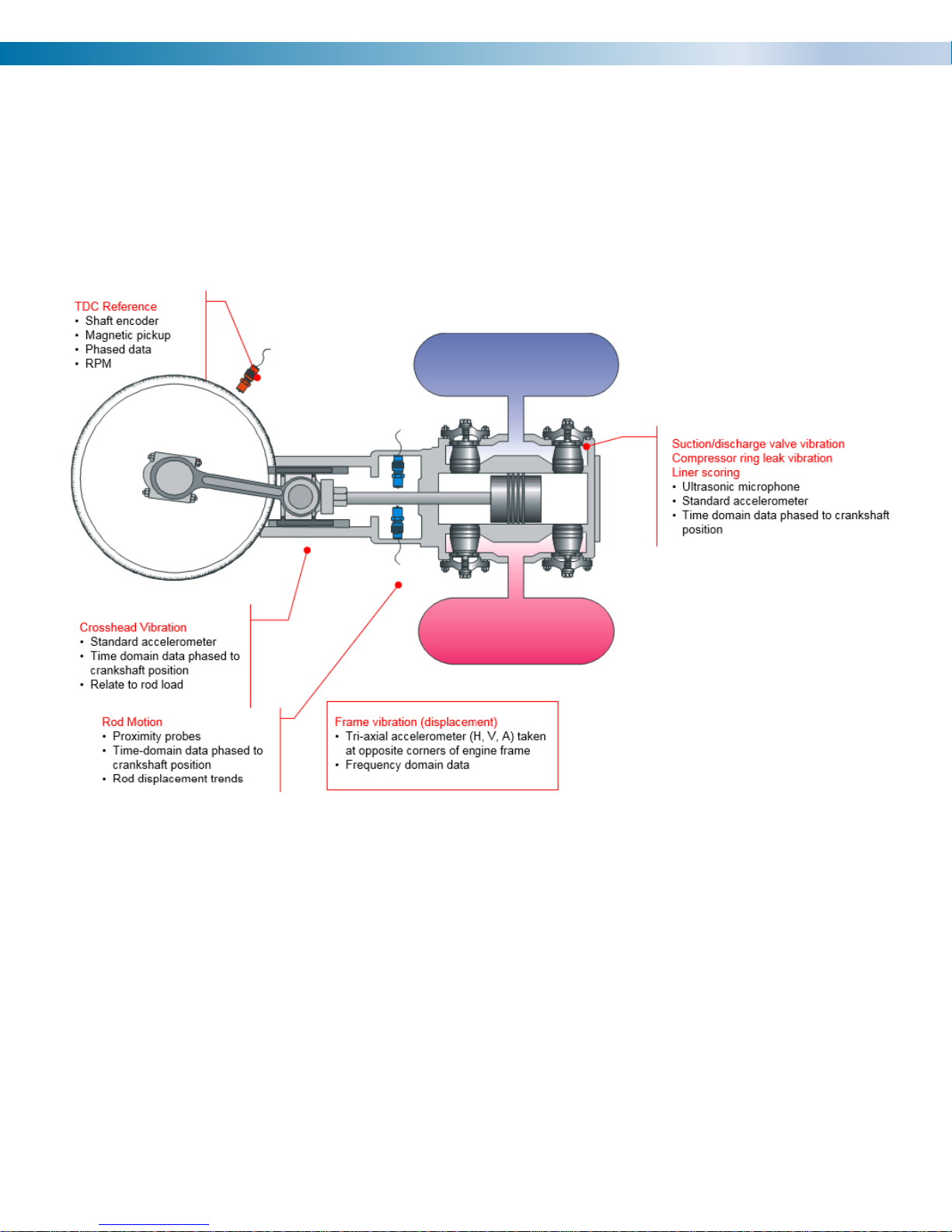
Compressor Data Collection Locations.......................................................................................................4
Batteries and Charging...............................................................................................................................7
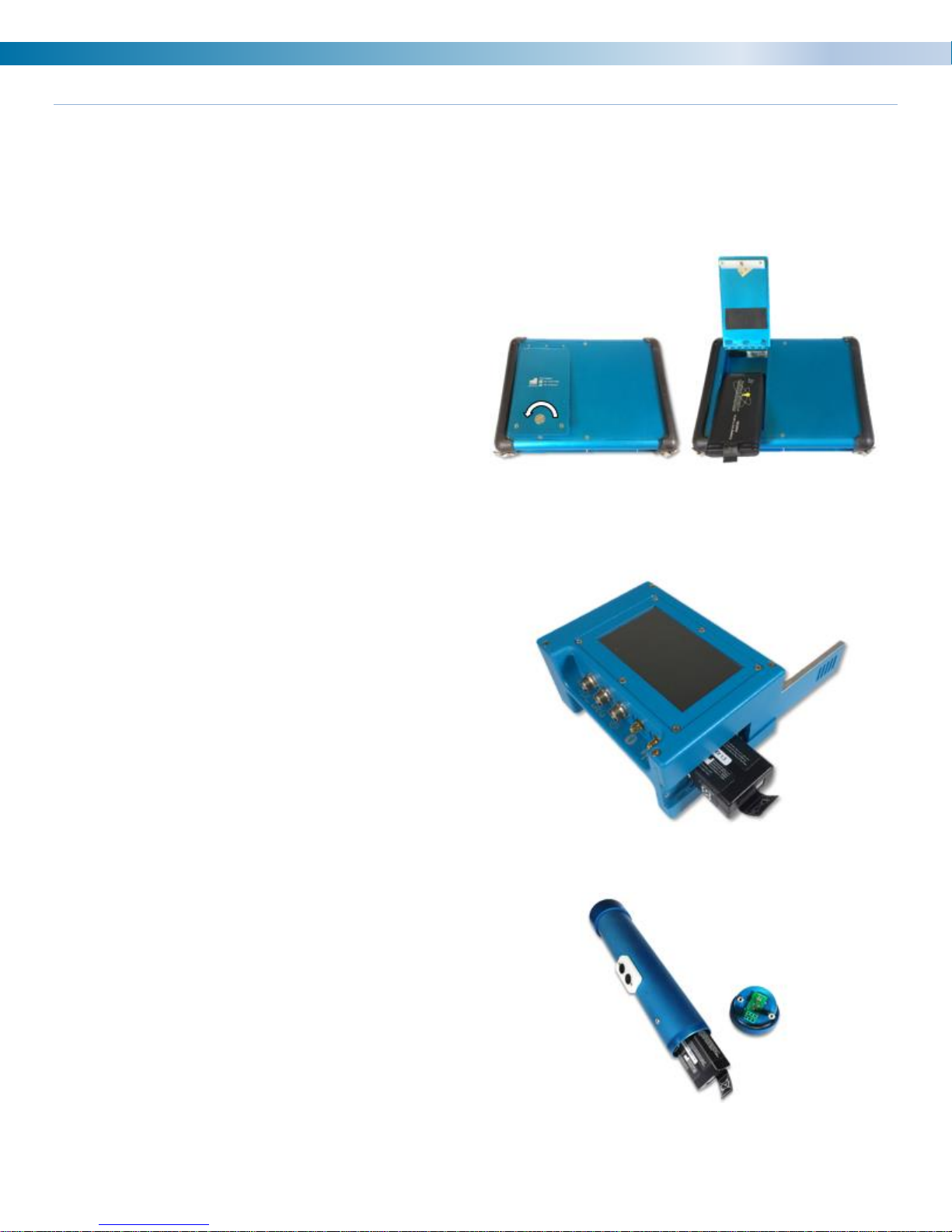
6400 Analyzer ............................................................................................................................................8
Adjusting Analyzer Screen Brightness......................................................................................................10
Adjusting Analyzer Date/Time ..................................................................................................................11
Encoder / Wireless Transmitter.................................................................................................................12
Encoder / Wireless Transmitter Functions ................................................................................................14
Selecting a Wireless Transmitter Channel................................................................................................20
Magnetic Pickup / Optical Sensor.............................................................................................................21
Cables......................................................................................................................................................22
Strobe (Timing) Light................................................................................................................................23
Engine Pressure Transducer....................................................................................................................24
Compressor Pressure Transducer............................................................................................................25
Pressure Transducer Calibration (Zeroing the Sensor).............................................................................26
Primary Ignition ........................................................................................................................................27
Secondary Ignition....................................................................................................................................28
Accelerometer..........................................................................................................................................29
Velocity Probe..........................................................................................................................................30
Ultrasonic / Infrared Temperature.............................................................................................................31
Ultrasonic Gain Adjustment......................................................................................................................32
Headphones.............................................................................................................................................34
/VA Kit Additional Items............................................................................................................................37

6400 Reference Manual
2
Why an Analysis Program?
The purpose of any Analysis Program is to assemble quality systems and personnel to perform regular
assessments of the condition and performance of the operation’s equipment assets.
Testing and analysis, when performed with consistency and regularity, can be a valuable tool for helping
predict and pinpoint mechanical or other problems that may be occurring within a process system to help
reduce costly down or offline time as well the repair or replacement of mechanical parts or components.
Goals
The analyzer is used to take measurements relating to vibration, ultrasonic, pressure, ignition, and temperature
for comparing the findings with predicted results to determine where problems may be, or about to be,
occurring on a machine. Things we are looking for might include:
Engine Assessments:
Condition Measurements and Items of Concern:
•Detonation
•Misfires
•Firing Pressure Imbalance
•Leaking Valves and Rings
•Worn or Scored Liners
•Primary and Secondary Ignition
•Turbo Charger Issues
Performance Measurements and Items of Concern:
•Combustion
•Fuel Consumption
•Horsepower
•Efficiency
Compressor Assessments:
Condition Measurements and Items of Concern:
•Leaking Valves and Rings and Packing
•Rider Band Wear
•Crosshead Wear
•Liner Damage
•Excessive Frame Vibration
•Lack of Rod Reversal
•Foundation or Grout Damage
•Looseness
Performance Measurements and Items of Concern:
•Horsepower
•Capacity
•Efficiency
•Valve Dynamics
•Gas Pulsations

6400 Reference Manual
3
Engine Data Collection Locations
Engine Data Collection Point Examples

6400 Reference Manual
4
Compressor Data Collection Locations
Compressor Pressure and Infrared Data

6400 Reference Manual
5
Compressor Vibration Data

6400 Reference Manual
6
Compressor Ultrasonic Data

6400 Reference Manual
7
Batteries and Charging
The 6400 analyzer kit comes standard with two different sized batteries. The analyzer uses the large battery,
while the encoder / wireless transmitter & strobe (timing) light use the smaller battery.
Note: Both batteries utilize the same battery charger that is provided with the 6400 analyzer kit.
6400 Analyzer Battery Removal and Installation:
•On the back of the analyzer use a coin to turn
the locking mechanism counterclockwise to
unlock the battery door.
•Replace the battery with a charged battery.
•Close the door and relock.
Note: Using the lowest analyzer screen brightness
level without making the screen hard to see for the
user will extend battery life.
Encoder / Wireless Transmitter Battery Removal
and Installation:
•Slide the door open on the side of the
encoder.
•Pull the tag on the battery to remove it.
•Replace with a charged battery.
•Close the door.
•Once a new battery is installed the encoder
will automatically turn on.
Note: To save battery life remove this battery while
the encoder is not in use.
Strobe (timing) light Battery Removal and
Installation:
•Unthread the back cover and pull the
connector straight out of the timing light.
•Pull tag to remove the battery from the
housing.
•Install a new battery.
•Replace plug and connector.
•Rethread on back cover. The cover does not
need to be extremely tight.

6400 Reference Manual
8
6400 Analyzer
The analyzer is used to measure voltage or mA signals coming from a sensor or transducer and translating it
into useful data by converting it into calculated values for determining the health and performance of the
machine being measured.
Windrock analyzers come in several configurations ranging in complexity depending upon the types of
machinery to be tested and data to be collected:
-6400 / CA 1-channel engine power cylinder balancer and ignition analyzer
-6400 / MA 2-channel reciprocating machinery maintenance analyzer
-6400 / DA 2-channel diesel engine analyzer
-6400 / PA 4-channel performance analyzer
-6400 / VA 4-channel vibration analyzer
Note: The MA, DA, and PA have the capability to add the VA (vibration) option to their current configuration
which provides additional vibration (FFT) data collection capabilities.
Note: The number of channels and options your analyzer has available will vary based on the specific model of
analyzer that you have.

6400 Reference Manual
9

6400 Reference Manual
10
Adjusting Analyzer Screen Brightness
The ability to adjust the brightness of the analyzer is available via the Utilities menu on the 6400-analyzer
screen. Once Utilities is selected, a menu list will be displayed on the analyzer. Select option 2 (System setup)
from the main utilities menu and then option 2 (Display) from the sub menu. Once selected the adjustment box
below will display on the analyzer screen. Use the arrows on the analyzer to adjust the screen brightness to
the desired setting and then select the ENTER (Blue) button on the analyzer to save the setting.
Once saved the analyzer will remember the setting the next time the analyzer is turned on.
Note: Using a brighter setting will consume more battery power and shorten the overall charge life of the
battery.
Press analyzer function key to open “Utilities”
menu on the analyzer.

6400 Reference Manual
11
Adjusting Analyzer Date/Time
The ability to adjust the date/time that displays on the analyzer is available via the Utilities menu on the 6400
analyzer screen. Once Utilities is selected, a menu list will be displayed on the analyzer. Select option 2
(System setup) from the main utilities menu and then option 3 (Date/time) from the sub menu. Once selected
the adjustment box below will display on the analyzer screen. Use the keypad on the analyzer to adjust the
date/time to the desired setting and then select the ENTER (blue) button on the analyzer to save the setting.
Note: The date/time can be automatically adjusted via connection of the analyzer to the Windrock MD software
on your PC. For this function to work properly the time zone on the analyzer must match the time zone on your
PC.
Press analyzer function key to open “Utilities”
menu on the analyzer.

6400 Reference Manual
12
Encoder / Wireless Transmitter
The encoder converts the rotational motion of the crankshaft into electrical signals. The encoder generates a
pulse per degree (PPD) signal and a pulse per revolution (PPR) signal for tracking crankshaft motion. The half
inch shaft is for connecting to a rotating element at running speed.
The analyzer takes the information from the encoder and preprocesses it to match the setup for the unit (2 or 4
stroke, A/B phase shift). This makes the encoder easier to use and the data easier to collect as you don’t need
to go to the encoder to make any changes after the initial setup.
The encoder also incorporates Mag Pickup, Prox. Probe or Optical input connectors for once per turn inputs
(TDC).
The DEG input is an optional input to track the angular velocity between TDC triggers.
The third connector is a 5 pin LEMO for a direct connection to the analyzer with an encoder cable. Cable sold
separately.
Note: The 6320 encoder cable is not compatible with the 6400.
The short antenna is for blue tooth connection that is currently used for firmware updates and is not required
for normal operation.
The long antenna is for sending speed information to the 6400 and is required when using the wireless
function.

6400 Reference Manual
13
The encoder has a touch screen with icon buttons.
The 6400 encoder has the ability of choosing from 8 different wireless frequencies by selecting the channel the
encoder is to use.
Wireless Channels and Frequencies:
•Channel 0 = 903.37 MHz
•Channel 1 = 906.37 MHz
•Channel 2 = 907.87 MHz
•Channel 3 = 909.37 MHz
•Channel 4 = 912.37 MHz
•Channel 5 = 915.37 MHz
•Channel 6 = 919.87 MHz
•Channel 7 = 921.37 MHz
Note: If a 6320 analyzer is running in the general vicinity of a 6400 analyzer interference will occur with the
6400 encoder / wireless transmitter signal if it is set to Channel 7. The 6320 transmitter signal is not compatible
with the 6400 hardware.
Note: When powered off the screen will turn back on by touching the screen. Be sure to remove encoder /
wireless transmitter battery when storing in equipment case to prevent encoder / wireless transmitter from
turning on and lowering battery charge.

6400 Reference Manual
14
Encoder / Wireless Transmitter Functions
Encoder (EN) –Requires access and connection to the crank or a shaft running at the same speed.

6400 Reference Manual
15
Magnetic Pickup (MP) - Uses a magnetic pickup plugged into an accelerometer cable to see a target on the
flywheel. The encoder can automatically determine whether a pin or hole is being detected and polarity of the
sensor wires is not critical so long as both wires have no reference to ground.
Setting TDC (top dead center / once-per-turn)
The threshold adjustment controls the
sensitivity or level detection of the signal. It
defaults to 20 (least sensitivity) and can be
adjusted up or down by slowly rotating the
shaft.
If the signal does not exceed the threshold
level, the device will not show an RPM number
and the threshold number on the gauge is red
as shown.
Once the signal level exceeds the threshold
level, the device will calculate an RPM and
display it if the RPM is within measuring range
as shown.
TIPS FOR SETTING THRESHOLD LEVEL
One characteristic of magnetic pickups is that their signal amplitude changes with the speed of the flywheel, ie,
as the speed increases, the signal gets larger, and as the speed decreases, the signal gets smaller. If the
threshold level is lowered from 20 until the tip of the signal is just detected while running at a higher speed, the
threshold setting may not work if the signal gets smaller at a lower speed. Therefore, it is recommended that
the threshold level is swept over the range of the gauge noting the upper and lower bound numbers where the
colors change between green and red and then setting the level halfway between them.
Noise or other artifact considerations
If noise is present or other artifacts such as a previously used pin on the flywheel which has not been
completely ground down, and the threshold number is set to a level that detects them, the RPM number can
become erratic or indicate a multiple of the correct rpm. For example, if a ground down pin was detected while
the engine/compressor was running at 300 rpm, the encoder would see a stable 600 rpm and the gauge
number would be green, therefore, the lower bound gauge number to reference would not be a red/green color
change but change to an incorrect rpm.

6400 Reference Manual
16
Setting DEG (degree)
The MP mode can also be configured to add a
second magnetic pickup for detecting degree
signals by pressing the /
button which toggles between TDC only mode
and TDC & DEG mode.
Note: Before changing to this mode, the user
must have already set TDC having a stable
RPM.
The TDC & DEG mode adds a indicator and a degree pickup mode icon that
configures the sensor for detection of either gear teeth or an arrangement of holes or pins on a flywheel.
Consecutive presses of the icon toggles between the two modes.
The threshold gage for the DEG pickup is
identical to the TDC gauge and should be
should be adjusted in the same way TDC
ONLY mode is except that the degree events
value is referenced during adjustment rather
than RPM.

6400 Reference Manual
17
Optical Pickup (OP) - This function uses an optical pickup that is plugged into the TDC port and it is triggered
from a piece of reflective tape that is mounted on the flywheel.
Like the MP mode, this mode also has a
/ button which toggles
between TDC only mode and TDC & DEG
mode.
Note: Before changing to this mode, the user
must have already set TDC having a stable
RPM.
The TDC & DEG mode also adds the
indicator.

6400 Reference Manual
18
Prox Negative (P-) - This mode accommodates a negative supply proximity probe that is looking at a hole or
pin target to obtain a TDC (Common with Bentley panels).
The threshold adjustment operates the same
as the MP mode except that It has a wider
range (0-40). Unlike magnetic pickups, prox
probe signal levels do not change with speed.
However, unlike magnetic pickups, which
have no DC component, prox probes can
have the AC signal appear over a wide DC
component range, making it necessary to
identify the upper and lower bounds for best
threshold selection.
The Prox waveform below provides an example for setting the best threshold level. It is essentially the same
approach as described for the MP mode.
a. Start with the max gauge value (40) which will usually result in no RPM reading and a gauge value in
RED.
b. Lower the value until a stable RPM reading shows and stable GREEN color for the gauge value which
for this example is 34 and an RPM of 250.
c. Continue lowering the level until the RPM changes and/or the gauge value turns RED. For this
example, a value of 9 detects another pulse from the uneven flywheel surface resulting in erratic RPM
and the gauge value color turns RED so 10 would be the last GREEN value.
d. Adjust the gauge level to the midpoint of 22 (34+10 / 2) which yields maximum separation from both the
uneven flywheel surfaces and the peak of the TDC signal.

6400 Reference Manual
19
Simulator (SM) –This is a way to be able to test the analyzer without being on a unit.
It is possible to use the timing light in this
mode to estimate speed on pumps/fans and
collect crank angle data where a speed
reference is not available. The range of this
feature is 150-1300 RPM. The
toggle button allows
for course / fine adjustment in the RPM
value.
NOTE: NEVER USE THIS MODE WHEN
YOU CAN USE THE ENCODER OR A
ONCE PER TURN MODE!
FCC Exposure Notice:
To maintain compliance with the RF exposure guidelines, place the unit at least 20cm from nearby persons.
Pour assurer la conformité aux directives relatives à l'exposition aux frequencies radio, le jouet doit êtreplacé à
au moins 20_cm des personnes à proximité.
This device complies with Industry Canada’s licence-exempt RSSs. Operation is subject to the following two
conditions:
(1) This device may not cause interference; and
(2) This device must accept any interference, including interference that may cause undesired operation of the
device.
Le présent appareil est conforme aux CNR d’Industrie Canada applicables aux appareils radio exempts de
licence. L’exploitation est autorisée aux deux conditions suivantes:
(1) l’appareil ne doit pas produire de brouillage, et
(2) l’utilisateur de l’appareil doit accepter tout brouillage radioélectrique subi, même si le brouillage est
susceptible d’en compromettre le fonctionnement.
Any changes or modifications not expressly approved by the party responsible for compliance could
void the user’s authority to operate the equipment.
This device has been designed to operate with the antennas supplied by Windrock. Antennas not
supplied by Windrock are strictly prohibited for use with this device. The required antenna impedance
is 50 ohms.
Table of contents
Other Windrock Measuring Instrument manuals
Popular Measuring Instrument manuals by other brands

Agilent Technologies
Agilent Technologies ESA-L1500A Installation note

Simrad
Simrad PI32 Operator's manual

Sibata
Sibata 080150-066 Operation manual

Spirax Sarco
Spirax Sarco 2000 Series Installation and maintenance instructions

Worldcast Systems
Worldcast Systems Audemat DVB-T Monitor user manual

CHY
CHY 831 Operator's manual