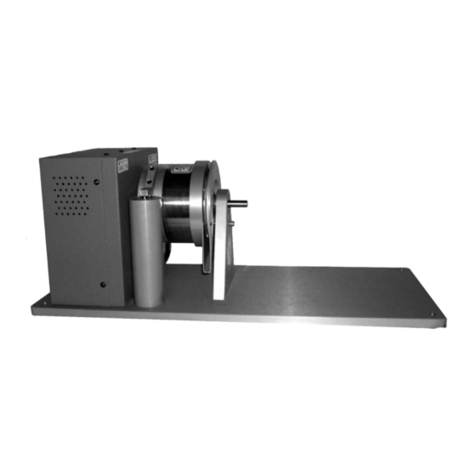
Magtrol WB Series User manual

User’s Manual
WB and PB Series
Eddy-Current and Magnetic
Powder Dynamometers
Via Paolo Uccello 4 - 20148 Milano

1st Edition - rev F – September 2015
While every precaution has been exercised in the compilation of this document to ensure
the accuracy of its contents, Magtrol assumes no responsibility for errors or omissions.
Additionally, no liability is assumed for any damages that may result from the use of the
information contained within this publication.
COPYRIGHT
Copyright ©2005-2015 Magtrol, Inc. All rights reserved.
Copying or reproduction of all or any part of the contents of this manual without the express
permission of Magtrol is strictly prohibited.
Purchase Record
Please record all model numbers and serial numbers of your
Magtrol equipment, along with the general purchase information.
The model number and serial number can be found on either
a silver identification plate or white label affixed to each unit.
Refer to these numbers whenever you communicate with a
Magtrol representative about this equipment.
Model Number: _____________________________
Serial Number: _____________________________
Purchase Date: _____________________________
Purchased From: _____________________________

i
Safety Precautions
WARNING! IN ORDER TO MINIMIZE RISKS, IT IS OF UTMOST
IMPORTANCE TO RESPECT THE CURRENT SAFETY
STANDARDS WHEN PLANNING, CONFIGURING AND
OPERATING THE MOTOR TEST SYSTEM.
1. Make sure that all Magtrol dynamometers and electronic products are earth-grounded, to
ensure personal safety and proper operation.
2. Check line voltage before operating electronic equipment.
3. Make sure that dynamometers and motors under test are equipped with appropriate safety
guards.
Note: Detailed information regarding Motor Test Protective Systems can
be found in Section 2.8 – Protective Systems.
4. Always select a coupling that matches the speed and braking torque of the tested system.
5. Wear protective glasses when working on a test bench.
6. Never wear a necktie or baggy clothes when standing close to the test bench.
7. Never stand too close to the running test bench or bend over a rotating shaft.
8. Electrically insulate the motor terminal block.
9. Always connect the motor envelope to earth ground.
10. Make sure that the safety circuitry of the motor control cannot be deactivated by accident.
WARNING! A DEFECT ON THE ELECTRICAL TRANSMISSION
LINE CAN CAUSE A SHORT-CIRCUIT WHICH CAN
PROPAGATE TO ALL CONNECTED INSTRUMENTS OR
PERSONS IN CONTACT WITH THE APPARATUS.

ii
The contents of this manual is subject to change without prior notice.
REVISION DATE
1st edition – rev. F - September 2015
TABLE OF REVISIONS
Revisions To This Manual
Date Edition Change Section(s)
09/02/15 1st Edition - rev F Page layout 3.1 / 3.1.2
04/21/15 1st Edition - rev E Remove WB2.7 HS version 1.2.1
04/21/15 1st Edition - rev E Remove the 1WB2.7 dynamometer 1.2.1 / 2.10 / 6.1.2
05/26/14 1st Edition - rev D Data sheets updated 1.2
02/26/14 1st Edition - rev C All references to DSP6001 changed to DSP7000 throughout manual
04/25/12 1st Edition - rev B Diagram (torque, power) for Tandem WB 115 updated 1.2.4
12/21/09 1st Edition - rev A The maximum input pressure was changed 3.1.2

iii
Table of Contents
1. INTRODUCTION .................................................................................................................................1
1.1 GENERAL DESCRIPTION ......................................................................................................................................... 1
1.2 DATA SHEETS ............................................................................................................................................................. 2
1.2.1 WB/PB 2.7 SERIES........................................................................................................................................ 2
1.2.2 WB/PB 43 SERIES......................................................................................................................................... 9
1.2.3 WB/PB 65 SERIES....................................................................................................................................... 17
1.2.4 WB/PB 115 SERIES..................................................................................................................................... 25
1.2.5 WB/PB 15 SERIES....................................................................................................................................... 33
2. INSTALLATION / MOUNTING ..........................................................................................................41
2.1 LOCKING THE DYNAMOMETER FOR TRANSPORT ......................................................................................... 41
2.1.1 WB/PB 2.7 SERIES...................................................................................................................................... 42
2.1.2 WB/PB 43 SERIES....................................................................................................................................... 43
2.1.3 WB/PB 65 SERIES....................................................................................................................................... 44
2.1.4 WB/PB 115 SERIES..................................................................................................................................... 45
2.1.5 WB/PB 15 SERIES....................................................................................................................................... 46
2.2 MOUNTING THE DYNAMOMETER TO THE TEST BENCH............................................................................... 47
2.2.1 ALIGNING THE DYNAMOMETERS ON THE TEST BENCH................................................................ 47
2.2.2 VIBRATIONS INDUCED BY THE TEST BENCH.................................................................................... 47
2.3 COUPLINGS............................................................................................................................................................... 48
2.4 MEASURING RANGE............................................................................................................................................... 49
2.5 DRAG TORQUE......................................................................................................................................................... 49
2.6 TOLERATED RADIAL AND AXIAL FORCES ....................................................................................................... 49
2.7 CONNECTING THE COOLING SYSTEM............................................................................................................... 50
2.8 PROTECTIVE SYSTEMS .......................................................................................................................................... 50
2.9 POWER/HEAT DISSIPATION ................................................................................................................................... 52
2.10TORQUE–SPEED–POWER CURVES ...................................................................................................................... 52
3. COOLING..........................................................................................................................................58
3.1 DYNAMOMETER COOLING................................................................................................................................... 58
3.1.1 CONNECTIONS........................................................................................................................................... 58
3.1.2 WATER FLOW AND PRESSURE ............................................................................................................... 58
3.1.3 COOLING WATER CONSUMPTION......................................................................................................... 58
3.1.4 TEMPERATURE SENSOR.......................................................................................................................... 58
3.2 OPEN-CIRCUIT COOLING SYSTEMS ................................................................................................................... 59
3.2.1 EXAMPLE.................................................................................................................................................... 59
3.3 CLOSED-CIRCUIT COOLING SYSTEMS .............................................................................................................. 60
3.3.1 EXAMPLE.................................................................................................................................................... 60
3.4 COOLING WATER ISSUES....................................................................................................................................... 61
3.4.1 IMPURITIES ................................................................................................................................................ 61
3.4.2 HARDNESS.................................................................................................................................................. 61
3.4.3 FILTERING .................................................................................................................................................. 62
3.4.4 CONTROLLING THE WATER FLOW RATE ............................................................................................ 62
3.4.5 WATER INHIBITORS.................................................................................................................................. 62
3.4.6 CONDENSATION........................................................................................................................................ 63
3.5 COOLING CIRCUIT PURGING ............................................................................................................................... 63

iv
Table of Contents Magtrol WB/PB Dynamometers
4. CONNECTIONS / CONFIGURATION ...............................................................................................64
4.1 CONNECTION TO MAGTROL MOTOR TESTING ELECTRONICS.................................................................... 64
4.1.1 MANUAL TEST CONFIGURATION ......................................................................................................... 64
4.1.2 PC-BASED TEST CONFIGURATION........................................................................................................ 65
4.2 TANDEM DYNAMOMETER CONFIGURATION................................................................................................... 66
4.2.1 ELECTROMAGNETIC CLUTCH............................................................................................................... 66
4.2.2 TRANSFORMER CONNECTION .............................................................................................................. 67
4.3 CONNECTION TO NON-MAGTROL ELECTRONIC CONTROL UNITS ............................................................ 68
4.3.1 POWER AND THERMOSTAT CONNECTION ......................................................................................... 68
4.3.2 TORQUE SIGNAL CONNECTION ............................................................................................................ 70
4.3.3 SPEED SIGNAL CONNECTION................................................................................................................ 71
5. OPERATING PRINCIPLES ...............................................................................................................72
5.1 EDDY-CURRENT DYNAMOMETERS (WB) .......................................................................................................... 72
5.2 MAGNETIC POWDER DYNAMOMETERS (PB) ................................................................................................... 72
5.3 WB VS. PB.................................................................................................................................................................. 72
6. CALIBRATION ..................................................................................................................................73
6.1 BASIC CALIBRATION INFORMATION ................................................................................................................. 73
6.1.1 CALIBRATION ARMS ................................................................................................................................ 73
6.1.2 CALIBRATION WEIGHT ........................................................................................................................... 74
6.2 CALIBRATION WITH MAGTROL MOTOR TESTING ELECTRONICS .............................................................. 75
6.3 CALIBRATION USING NON-MAGTROL ELECTRONIC CONTROL UNITS..................................................... 75
6.4 CALIBRATION OF OVERLOAD PROTECTION .................................................................................................... 75
6.4.1 WB/PB 43 SERIES....................................................................................................................................... 76
6.4.2 WB/PB 65 SERIES....................................................................................................................................... 77
6.4.3 WB/PB 115 SERIES..................................................................................................................................... 78
7. MAINTENANCE AND REPAIR .........................................................................................................79
7.1 MAINTENANCE........................................................................................................................................................ 79
7.2 REPAIR ....................................................................................................................................................................... 79
7.3 SENDING EQUIPMENT TO MAGTROL FOR MAINTENANCE/REPAIR........................................................... 79

v
Table of ContentsMagtrol WB/PB Dynamometers
TABLE OF FIGURES
2. INSTALLATION / MOUNTING
Figure 2–1 WB/PB 2.7 Load Cell Locking System................................................................................................................................... 42
Figure 2–2 WB/PB 43 Load Cell Locking System.................................................................................................................................... 43
Figure 2–3 WB/PB 65 Load Cell Locking System.................................................................................................................................... 44
Figure 2–4 WB/PB 115 Load Cell Locking System.................................................................................................................................. 45
Figure 2–5 WB/PB 15 Load Cell Locking System.................................................................................................................................... 46
Figure 2–6 Couplings Using Key Clamping ............................................................................................................................................ 48
Figure 2–7 Example of Protective System................................................................................................................................................ 51
Figure 2–8 WB 2.7 Ratings Curve ........................................................................................................................................................... 52
Figure 2–9 PB 2.7 Ratings Curve ............................................................................................................................................................ 53
Figure 2–10 WB 43 Ratings Curve .......................................................................................................................................................... 53
Figure 2–11 PB 43 Ratings Curve ........................................................................................................................................................... 54
Figure 2–12 WB 65 Ratings Curve .......................................................................................................................................................... 54
Figure 2–13 PB 65 Ratings Curve ........................................................................................................................................................... 55
Figure 2–14 WB 115 Ratings Curve ........................................................................................................................................................ 55
Figure 2–15 PB 115 Ratings Curve ......................................................................................................................................................... 56
Figure 2–16 WB 15 Ratings Curve .......................................................................................................................................................... 56
Figure 2–17 PB 15 Ratings Curve ........................................................................................................................................................... 57
3. COOLING
Figure 3–1 Open-circuit Cooling Example.............................................................................................................................................. 59
Figure 3–2 Closed-circuit Cooling Example ........................................................................................................................................... 60
4. CONNECTIONS / CONFIGURATION
Figure 4–1 Manual Test Configuration.................................................................................................................................................... 64
Figure 4–2 PC-Based Test Configuration with M-TEST Software........................................................................................................... 65
Figure 4–3 Tandem Configuration ........................................................................................................................................................... 66
Figure 4–4 Supply Cable Between 24 V DC Transformer and DES Power Supply ................................................................................. 67
Figure 4–5 Control Signal Cable for WB/PB 2.7 and 43 Tandem Dynamometer Clutches..................................................................... 67
Figure 4–6 Control Signal Cable for WB/PB 65, 115 and 15 Tandem Dynamometer Clutches .............................................................. 67
Figure 4–7 Connector Pin Configuration for WB/PB 2.7 Dynamometer Power ..................................................................................... 69
Figure 4–8 Connector Pin Configuration for WB/PB 43 Dynamometer Power and Temperature Measurement ................................... 69
Figure 4–9 Connector Pin Configuration for WB/PB 65, 115 and 15 Dynamometer Power and Temperature Measurement ............... 69
Figure 4–10 Connector Pin Configuration for WB/PB 2.7 and 43 Dynamometer Torque Signals ......................................................... 70
Figure 4–11 Connector Pin Configuration for WB/PB 65, 115 and 15 Dynamometer Torque Signals .................................................. 70
Figure 4–12 Connector Pin Configuration for WB/PB 2.7 and 43 Dynamometer Speed Signals........................................................... 71
Figure 4–13 Connector Pin Configuration for WB/PB 65, 115 and 15 Dynamometer Speed Signals.................................................... 71
6. CALIBRATION
Figure 6–1 Calibration Arm Mounting .................................................................................................................................................... 73
Figure 6–2 WB/PB 43 Overload Protection Calibration......................................................................................................................... 76
Figure 6–3 WB/PB 65 Overload Protection Calibration......................................................................................................................... 77
Figure 6–4 WB/PB 115 Overload Protection Calibration....................................................................................................................... 78

vi
Preface
PURPOSE OF THIS MANUAL
This manual contains information required for the installation and general use of Magtrol’s WB
Series and PB Series Dynamometers. To achieve maximum capability and ensure proper use, please
read this manual in its entirety before operating. Keep the manual in a safe place for quick reference
whenever a question should arise.
WHO SHOULD USE THIS MANUAL
This manual is intended for bench test operators who are going to use a WB Eddy-current or PB
Magnetic Powder Dynamometer in order to determine the torque and power of a motor in relation
to its speed. It is assumed that the user has sufficient knowledge in mechanics and electronics to be
able to install/operate these WB/PB Dynamometers without risk.
MANUAL ORGANIZATION
This section gives an overview of the structure of the manual and the information contained therein.
Some information has been deliberately repeated in different sections of the document to minimize
cross-referencing and to facilitate understanding through reiteration.
The structure of the manual is as follows:
Chapter 1: INTRODUCTION – Contains technical data sheets of all Magtrol WB/PB Series
Dynamometers, which describe their technical characteristics and give a brief
overview of their application fields.
Chapter 2: INSTALLATION / MOUNTING – Provides information needed for the mounting of
the dynamometers, as well as limits and precautions to observe during operation.
Chapter 3: COOLING – Describes the necessary measures to take in order to guaranty an
optimal dynamometer operating temperature.
Chapter 4: CONNECTION / CONFIGURATION – Provides information about the wiring
between the dynamometers and the electronic control units, as well as tandem setups
of dynamometers.
Chapter 5: OPERATING PRINCIPLES – Describes the physical phenomena on which the Eddy-
current (WB) and magnetic powder (PB) dynamometer technology is based.
Chapter 6: CALIBRATION – Provides recommended calibration schedules along with step-
by-step instructions for the calibration procedure.
Chapter 7: MAINTENANCE AND REPAIR – Provides information on how to return a WB/PB
series dynamometer to Magtrol for servicing, preventative maintenance or repair.

vii
Magtrol WB/PB Dynamometers Preface
CONVENTIONS USED IN THIS MANUAL
The following symbols and type styles may be used in this manual to highlight certain parts of the
text:
Note: This is intended to draw the operator’s attention to complementary
information or advice relating to the subject being treated. It
introduces information enabling the correct and optimal functioning
of the product to be obtained.
Caution : this is used to draw the operator'sattention to information,
direCtives, proCedures, etC. whiCh, if ignored, may result in damage
being Caused to the material being used. the assoCiated text
desCribes the neCessary preCautions to take and the ConsequenCes
that may arise if the preCautions are ignored.
WARNING! THIS INTRODUCES DIRECTIVES, PROCEDURES,
PRECAUTIONARY MEASURES, ETC. WHICH MUST BE
EXECUTED OR FOLLOWED WITH THE UTMOST CARE
ANDATTENTION, OTHERWISE THE PERSONAL SAFETY
OF THE OPERATOR OR THIRD PARTIES MAY BE PUT
AT RISK. THE READER MUSTABSOLUTELY TAKE NOTE
OF THE ACCOMPANYING TEXT, AND ACT UPON IT,
BEFORE PROCEEDING FURTHER.

viii
Magtrol WB/PB DynamometersPreface
This page was intentionally left blank

1
1. Introduction
1.1 GENERAL DESCRIPTION
The WB and PB Dynamometers manufactured by Magtrol are used for testing all types of motors
and rotational systems, and measuring their torque and power according to their speed. They have
been specially designed for integration in a complete motor testing system.
The WB Series Dynamometers feature Eddy-current braking systems and are able to be operated
at high speeds. However, as their braking torque is proportional to their speed, they cannot be used
at low speeds.
The PB Series Dynamometers feature magnetic powder brakes and are therefore appropriate for low
and medium-speed testing. Due to their design, they generate their maximum torque at standstill.
However, their maximum speed is limited to avoid the magnetic powder being centrifuged.
To combine the advantages of both designs, Magtrol offers a tandem mounting of both dynamometer
types for applications requiring measurements on a wide range of speeds.

2
Magtrol WB/PB DynamometersChapter 1 – Introduction
1.2 DATA SHEETS
1.2.1 WB/PB 2.7 SerieS
WB/PB 2.7
Data Sheet
WB/PB 2.7 Series Eddy-Current
and Powder Dynamometers
1
www.magtrol.com
MAGTROL
FEATURES
• 9ModelswithMaximumTorquefrom300mN·mto
2400mN·m(42oz·into340oz·in)
• BrakingPower:20Wto1kW
• StableBrakingTorque,withoutShock
• LowMomentofInertia
• LowResidualTorque
• OperationinEitherRotationalDirection
• BrakingTorqueMeasurementIncluded
• OptionalSpeedMeasurement
• RatedTorqueAvailableFromZeroSpeed(Powder
Dynamometers)
• IntegratedOpticalSpeedSensor
DESCRIPTION
Eddy-CurrentBrakeDynamometers(WBseries)areidealfor
applicationsrequiringhighspeedsandalsowhenoperatingin
themiddletohighpowerrange.Eddy-CurrentBrakesprovide
increasingtorqueasthespeedincreases,reachingpeaktorque
atratedspeed.Thedynamometershavelowinertiaasaresult
ofsmallrotordiameter.Brakecoolingisprovidedbyawater
circulationsystem,whichpassesinsidethestatortodissipate
heatgeneratedbythebrakingpower.The
watercoolingintheWBprovideshigh
continuouspowerratings(max.1kW).
PowderBrakeDynamometers(PB
series)areidealforapplications
operating in the low to middle speed
rangeorwhenoperatinginthemiddle
tohightorquerange.PowderBrakes
providefull torque at zero speed and
arewater-cooled,allowingforpower
ratingsupto600W.BothWBand
PBDynamometershaveaccuracyratingsof±2%fullscale
-dependingonsizeandsystemconfiguration.
APPLICATIONS
Mountedontestbenches,theWB/PB2.7SeriesDynamometers
allowperformanceandreliabilitytestingondrivingelements
suchasservomotors,micromotorsforcameras,smallfans,
dentaldrills,gearedmotors,smallreductiongears,pneumatic
equipment,hydraulictransmissionsystemsandmotorsforsmall
domesticappliances.
MOTOR TESTING SYSTEMS
Magtrol’sM-TEST 7 Softwareisastate-of-the-artmotor
testingprogramforWindows®-baseddataacquisition.Used
withaMagtrolDSP7000ProgrammableDynamometer
Controller,MagtrolM-TEST7Softwareprovidesthecontrol
ofanyMagtrolEddy-CurrentorPowderBrakeDynamometer
andrunstestsequencesinamannerbestsuitedtotheoverall
accuracyandefficiencyoftheMagtrolMotorTestSystem.
ThedatathatisgeneratedbyMagtrol’s
MotorTestingSoftwarecanbestored,
displayedandprintedintabularor
graphicformats,andcanbeeasily
importedintoaspreadsheet.
WritteninLabVIEW™,M-TEST7has
theflexibilitytotestamajorityofmotor
typesinavarietyofways.Becauseof
LabVIEW’sversatility,obtainingdata
fromothersources(e.g.thermocouples),
controllingmotorpowerandproviding
audio/visualindicatorsisrelativelyeasy.
Magtrol’sM-TEST7Softwareisidealforsimulatingloads,
cyclingtheunitundertestandmotorramping.Becauseitis
easytogatherdataandduplicatetests,thesoftwareisideal
foruseinengineeringlabs.Testscanbeprogrammedtorun
ontheirownandsavedforfutureuseallowingforvaluable
timesavingsinproductiontestingandincoming/outgoing
inspection.
Model 4 WB-2.7-8K Eddy-Current Dynamometer
Magtrol offers three types of dynamometer
brakes to absorb load: Hysteresis, Eddy
Current and Magnetic Powder. Each type
of Dynamometer has advantages and
limitations and choosing the correct one will
depend largely on the type of testing to be
performed. With over 50 models to choose
from, Magtrol Sales professionals are readily
available to assist in selecting the proper
Dynamometer to meet your testing needs.

3
Magtrol WB/PB Dynamometers Chapter 1 – Introduction
2
MAGTROL
TM Torque
Transducer
USB
PC
M-TEST
DSP7002 Dynamometer Controller
Excitation
Torque
TSC 401
Torque-Speed
Conditioner
DES Power Supply
Speed
Eddy-Current (WB)
OR Powder Brake (PB)
Dynamometer
USB
PC
M-TEST
Excitation
Torque
TSC 401
Torque-Speed
Conditioner
DES Power Supply
Speed
Eddy-Current (WB)
OR Powder Brake (PB)
Dynamometer
DSP7001 Dynamometer Controller
single DYnaMoMeter conFigurations
TheDynamometerscanbecomplementedbyvariouselectronicmodulessuchastheDES410PowerSupply,TSC401
Torque/
SpeedConditionerandDSP7000HighSpeedProgrammableDynamometerController.
MagtrolalsooffersIn-LineTorqueTransducersforextremelyaccuratetorqueandspeedmeasurementwithhighnoise
immunity.
Thetransducersemployauniquenon-contactdifferentialtransformertorquemeasuringtechnologywhichpreventsthe
rotation
ofelectroniccomponentsduringoperation,withouttheusageofsliprings.Foradynamic,high-precisionsystem,the
torque
transducercanbemountedinlinebetweentheunitundertestandthedynamometer.
System Configurations
WB/PB 2.7

4
Magtrol WB/PB DynamometersChapter 1 – Introduction
3
MAGTROL
Specifications
WB DYnaMoMeter ratings
TheWBEddy-CurrentDynamometersdeveloptheirfullpower
athighrotationspeeds.The2.7Seriesisparticularlyintended
* Voltage at 20 °C is 15 volts.
formotorswhichrotateathighspeeds,upto50,000rpm.The
brakingtorquedependsontherotationspeed.
eDDY-current DYnaMoMeter operating principles
WB torque–speeD–poWer curves
Thediagrambelowshowsthecharacteristiccurvesforthe2.7SeriesEddy-CurrentDynamometers.
Optical Speed Sensor
Each2.7SeriesWBDynamometerhasanopticalspeedsensor
witha30-bitpulsewheeldeliveredasstandard.
Cooling Water Consumption
ForallWBmodels: ≈30l/kWhat∆t=30°C (Metric)
≈8gal/kWhat∆t=86°F (US)
1000
100
10
1000
100
10
100 1000 10,000
50,000 rpm15,915 rpm
100,000
Speed Limit for WB
Rotation Speed (rpm)
Torque (mN·m)
Power (W)
4 WB 2.7-8-K (TORQUE)
4 WB 2.7-8-K
(POWER)
3 WB 2.7-8-K
(POWER)
3 WB 2.7-8-K (TORQUE)
2 WB 2.7-8-K (TORQUE)
2
W
B 2.7-
8-
K (PO
W
ER
)
Model Rated Torque Drag Torque
De-energized Nominal Input Inertia Rated
Power
Rated
Speed
Max. Speed Excitation
Current*
standard version
N·m oz·in mN·m oz·in kg·m² lb·ft·s² W rpm rpm A
2 WB 2.7-8K 0.30 42.4 9 1.27 2.33 × 10⁻⁵ 1.71 × 10⁻⁵ 500 15,915 50,000 1.0
3 WB 2.7-8K 0.45 63.7 9 1.27 3.18 × 10⁻⁵ 2.34 × 10⁻⁵ 750 15,915 50,000 1.5
4 WB 2.7-8K 0.60 84.9 12 1.69 4.03 × 10⁻⁵ 2.97 × 10⁻⁵ 1000 15,915 50,000 2.0
WB 2.7

5
Magtrol WB/PB Dynamometers Chapter 1 – Introduction
4
MAGTROL
Specifications
pB DYnaMoMeter ratings
* Voltage at 20 °C is 24 volts.
poWDer DYnaMoMeter operating principles
pB torque–speeD–poWer curves
Thediagramsbelowshowsthecharacteristiccurvesforthe2.7SeriesPowderDynamometers.
Optical Speed Sensor
Each2.7SeriesPBDynamometerhasanopticalspeedsensor
witha30-bitpulsewheeldeliveredasstandard.
** Cooling Circuit
The2.7SeriesPBDynamometersareavailablewith(K)or
withoutacoolingcircuit.Thecoolingwaterconsumptionfor
allPB-8Kmodelsis: ≈30l/kWhat∆t=30°C (Metric)
≈8gal/kWhat∆t=86°F (US)
4 PB 2.7-8-K (POWER)
2 PB 2.7-8-K (POWER)
1 PB 2.7-8-K (POWER)
1000
100
10
1000
100
10
10 100 1000 10,000
10,000 rpm2390 rpm
100,000
Speed Limit for PB
Rotation Speed (rpm)
Torque (mN·m)
Power (W)
4 PB 2.7-8-K (TORQUE)
2 PB 2.7-8-K (TORQUE)
1 PB 2.7-8-K (TORQUE)
4 PB 2.7-8 (POWER)
2 PB 2.7-8 (POWER)
1 PB 2.7-8 (POWER)
1000
100
10
1000
100
10
10 100 1000 10,000
3000 rpm320 rpm
100,000
Speed Limit for PB
Rotation Speed (rpm)
Torque (mN·m)
Power (W)
4 PB 2.7-8 (TORQUE)
2 PB 2.7-8 (TORQUE)
1 PB 2.7-8 (TORQUE)
ThePBPowderDynamometerscontain,astheirname
suggests,amagneticpowder.Theelectricalcurrentpassing
throughthecoilgeneratesamagneticfield,whichchanges
thepropertyofthepowder,thusproducingasmoothbraking
torquethroughfrictionbetweenrotorandstator.ThePowder
Dynamometers(PB)producetheirratedtorqueatzero
speed.Theelementtobetestedcanbeloadedatstandstillto
determinethestartingtorque.
Model Rated Torque Drag Torque
De-energized Nominal Input Inertia Rated
Power
Rated
Speed
Max.
Speed
Excitation
Current*
N·m oz·in mN·m oz·in kg·m² lb·ft·s² W rpm rpm A
1 PB 2.7-8 0.6 84 18 2.54 1.49 × 10⁻⁵ 1.09 × 10⁻⁵ 20 320 3000 0.5
2 PB 2.7-8 1.2 169 30 4.24 2.33 × 10⁻⁵ 1.71 × 10⁻⁵ 40 320 3000 1
4 PB 2.7-8 2.4 339 48 6.79 4.03 × 10⁻⁵ 2.97 × 10⁻⁵ 80 320 3000 2
1 PB 2.7-8K ** 0.6 84 18 2.54 1.49 × 10⁻⁵ 1.09 × 10⁻⁵ 150 2390 10,000 0.5
2 PB 2.7-8K ** 1.2 169 30 4.24 2.33 × 10⁻⁵ 1.71 × 10⁻⁵ 300 2390 10,000 1
4 PB 2.7-8K ** 2.4 339 48 6.79 4.03 × 10⁻⁵ 2.97 × 10⁻⁵ 600 2390 10,000 2
PB 2.7

6
Magtrol WB/PB DynamometersChapter 1 – Introduction
5
MAGTROL
Dimensions
DYnaMoMeters With cooling circuit
Cooling water connection Ø 6 mm (
≈
0.24 in)
TORQUEEXCITATION SPEED
Ta pping for
calibration arm
ØK Z
H
J
LM
ØKK
ØD
FFFE C
A
B
T (removable calibration arm)
102 mm (for N·m)*
R
Q
Y
S
N
P
V
*Calibration in N·m
with weight in kg
NOTE:
Original dimensions are in Metric units. Dimensions converted to English units have been rounded up to 2 decimal places.
Model units A B C D E F H J K L M
1 PB 2.7-8-K
mm 138 98 56 Ø 8h5 36 20 190 210 Ø 6.4 10 10
in 5.43 3.86 2.2 Ø0.3148
0.3149 1.42 0.79 7.48 8.27 Ø 0.252 0.39 0.39
2 WB 2.7-8-K / 2 PB 2.7-8-K
mm 162 122 80 Ø 8h5 24 20 190 210 Ø 6.4 10 10
in 6.38 4.8 3.15 Ø0.3148
0.3149 0.94 0.79 7.48 8.27 Ø 0.252 0.39 0.39
3 WB 2.7-8-K
mm 186 146 104 Ø 8h5 12 20 190 210 Ø 6.4 10 10
in 7.32 5.75 4.09 Ø0.3148
0.3149 0.47 0.79 7.48 8.27 Ø 0.252 0.39 0.39
4 WB 2.7-8-K / 4 PB 2.7-8-K
mm 210 170 128 Ø 8h5 --- 20 190 210 Ø 6.4 10 10
in 8.27 6.69 5.04 Ø0.3148
0.3149 --- 0.79 7.48 8.27 Ø 0.252 0.39 0.39
Model units N P Q R S T V Y Z FF KK Weight
1 PB 2.7-8-K
mm 80 100 45 90 ±0.1 152 220 7.6 48 81 16 Ø 10.5 4.2 kg
in 3.15 3.94 1.77 3.547
3.539 5.98 8.66 0.299 1.89 3.19 0.63 Ø 0.413 9.26 lb
2 WB 2.7-8-K / 2 PB 2.7-8-K
mm 80 100 45 90 ±0.1 152 220 7.6 48 69 16 Ø 10.5 5.3 kg
in 3.15 3.94 1.77 3.547
3.539 5.98 8.66 0.299 1.89 2.72 0.63 Ø 0.413 11.68 lb
3 WB 2.7-8-K
mm 80 100 45 90 ±0.1 152 220 7.6 48 57 16 Ø 10.5 6.4 kg
in 3.15 3.94 1.77 3.547
3.539 5.98 8.66 0.299 1.89 2.24 0.63 Ø 0.413 14.11 lb
4 WB 2.7-8-K / 4 PB 2.7-8-K
mm 80 100 45 90 ±0.1 152 220 7.6 48 45 16 Ø 10.5 7.5 kg
in 3.15 3.94 1.77 3.547
3.539 5.98 8.66 0.299 1.89 1.77 0.63 Ø 0.413 16.53 lb
WB/PB 2.7

7
Magtrol WB/PB Dynamometers Chapter 1 – Introduction
6
MAGTROL
Dimensions
DYnaMoMeters Without cooling circuit
TORQUEEXCITATION SPEED
T (removable calibration arm)
102 mm (for N·m)*
H
J
C
A
B
ØKK
N
P
F
E
R
Q
S
V
ØD
Z
ØK
LM
*Calibration in N·m
with weight in kg
Ta pping for
calibration arm
FF
NOTE:
Original dimensions are in Metric units. Dimensions converted to English units have been rounded up to 2 decimal places.
Model units A B C D E F H J K L M
1 PB 2.7-8
mm 138 98 56 Ø 8h5 36 20 190 210 Ø 6.4 10 10
in 5.43 3.86 2.2 Ø0.3148
0.3149 1.42 0.79 7.48 8.27 Ø 0.252 0.39 0.39
2 PB 2.7-8
mm 162 122 80 Ø 8h5 24 20 190 210 Ø 6.4 10 10
in 6.38 4.8 3.15 Ø0.3148
0.3149 0.94 0.79 7.48 8.27 Ø 0.252 0.39 0.39
4 PB 2.7-8
mm 210 170 128 Ø 8h5 --- 20 190 210 Ø 6.4 10 10
in 8.27 6.69 5.04 Ø0.3148
0.3149 --- 0.79 7.48 8.27 Ø 0.252 0.39 0.39
Model units N P Q R S T V Z FF KK Weight
1 PB 2.7-8
mm 80 100 45 90 ±0.1 131 220 7.6 81 16 Ø 10.5 3.8 kg
in 3.15 3.94 1.77 3.547
3.539 5.16 8.66 0.299 2.72 0.63 Ø 0.413 8.38 lb
2 PB 2.7-8
mm 80 100 45 90 ±0.1 131 220 7.6 69 16 Ø 10.5 4.6 kg
in 3.15 3.94 1.77 3.547
3.539 5.16 8.66 0.299 3.19 0.63 Ø 0.413 10.14 lb
4 PB 2.7-8
mm 80 100 45 90 ±0.1 131 220 7.6 45 16 Ø 10.5 6.2 kg
in 3.15 3.94 1.77 3.547
3.539 5.16 8.66 0.299 2.72 0.63 Ø 0.413 13.67 lb
PB 2.7

8
Magtrol WB/PB DynamometersChapter 1 – Introduction
WB/PB 2.7
Due to the continual development of our products, we reserve the right to modify specifications without forewarning.
www.magtrol.com
MAGTROL INC
70 Gardenville Parkway
Buffalo, New York 14224 USA
Phone: +1 716 668 5555
Fax: +1 716 668 8705
MAGTROL SA
Route de Montena 77
1728 Rossens / Fribourg, Switzerland
Phone: +41 (0)26 407 3000
Fax: +41 (0)26 407 3001
Subsidiaries in:
Germany • France
China • India
Worldwide Network
of Sales Agents
Ordering Information
WBPB27-US 04/15
DYNAMOMETER MODELS
SYSTEM OPTIONS AND ACCESSORIES
DYNAMOMETER OPTIONS
Vertical Mounting (V)
VerticalMountingisavailableontheEddy-Current(WB)
Dynamometeronly.Theverticalversionhasanadapted
bearingfittinganditsmaximumspeedislimited.
Mechanical Rotor Blocking Device (MB)
Amechanicalrotorblockingdevice,whichallowslockedrotor
testing,isavailablefortheWBDynamometer.
ORDERING INFORMATION
Ifoneofthelistedoptionsisdesired,pleasefollowthe
dynamometermodel(seetableabove)withadashandthen
theappropriatesuffix(asnotedinparenthesis).Forexample,
a Model 1WB2.7-8KEddy-CurrentDynamometerwith a
maximumspeedratingof70,000rpmisa1WB2.7-8K-HS.
Example: 1 WB 2.7-8K - HS
Dynamometer Model Option
DESCRIPTION MODEL / PART #
ELECTRONICS
High Speed Programmable Dynamometer Controller DSP7000
Torque-Speed Conditioner (includes necessary cables) TSC 401/111
Power Supply (includes necessary cables) DES 410/111
High Speed Single-Phase Power Analyzer 6510e
High Speed Three-Phase Power Analyzer 6530
SOFT-
WARE
M-TEST 7 Motor Testing Software M-TEST 7
Temperature Testing Hardware HW-TTEST
MISC
Couplings, Thermostatic Sluice, Pressure Sensitive Switch On Request
Water Cooling System for Brake On Request
Calibration Weights On Request
Eddy-Current Powder with
Cooling Circuit
Powder without
Cooling Circuit
2 WB 2.7-8K 1 PB 2.7-8K 1 PB 2.7-8
3 WB 2.7-8K 2 PB 2.7-8K 2 PB 2.7-8
4 WB 2.7-8K 4 PB 2.7-8K 4 PB 2.7-8

9
Magtrol WB/PB Dynamometers Chapter 1 – Introduction
1.2.2 WB/PB 43 SerieS
WB/PB 43
Data Sheet
WB/PB 43 Series Eddy-Current
and Powder Dynamometers
1
www.magtrol.com
MAGTROL
FEATURES
• 4ModelswithMaximumTorquefrom1.5N·mto10
N·m(1.1lb·ftto7.3lb·ft)
• BrakingPower:0.5kWto3kW
• StableBrakingTorque,withoutShock
• LowMomentofInertia
• LowResidualTorque
• OperationinEitherRotationalDirection
• BrakingTorqueMeasurementIncluded
• HighRotationalSpeed
• RatedTorqueAvailableFromZeroSpeed(Powder
Dynamometers)
• IntegratedOpticalSpeedSensor
DESCRIPTION
Eddy-CurrentBrakeDynamometers(WBseries)areidealfor
applicationsrequiringhighspeedsandalsowhenoperatingin
themiddletohighpowerrange.Eddy-CurrentBrakesprovide
increasingtorqueasthespeedincreases,reachingpeaktorque
atratedspeed.Thedynamometershavelowinertiaasaresult
ofsmallrotordiameter.Brakecoolingisprovidedbyawater
circulationsystem,whichpassesinside
thestatortodissipateheatgeneratedby
thebrakingpower.Thewatercooling
intheWBprovideshighcontinuous
powerratings(max.3kW).
PowderBrakeDynamometers(PB
series)areidealforapplicationsoperating
inthelowtomiddlespeedrangeor
whenoperatinginthemiddletohigh
torquerange.PowderBrakesprovide
fulltorqueatzerospeedandarewater-
cooled,allowingforpowerratingsupto1kW.BothWBand
PBDynamometershaveaccuracyratingsof±0.3%to±0.5%full
scale,dependingonsizeandsystemconfiguration.
APPLICATIONS
Mountedontestbenches,WB/PB43SeriesDynamometers
allowperformanceandreliabilitytestingondrivingelements
suchaselectricmotors,combustionengines,hand-helddrills,
windshieldwipermotors,servomotors,fans,gearedmotors,
reductiongears,pneumaticequipment,hydraulictransmission
systemsandmotorsfordomesticappliances.
MOTOR TESTING SYSTEMS
Magtrol’sM-TEST 7 Softwareisastate-of-the-artmotor
testingprogramforWindows®-baseddataacquisition.Used
withaMagtrolDSP7000ProgrammableDynamometer
Controller,MagtrolM-TEST7Softwareprovidesthecontrol
ofanyMagtrolEddy-CurrentorPowderBrakeDynamometer
andrunstestsequencesinamannerbestsuitedtotheoverall
accuracyandefficiencyoftheMagtrol
Motor Test System.The data that is
generatedbyMagtrol’sMotorTesting
Softwarecanbestored,displayedand
printedin tabularor graphic formats,
andcanbeeasilyimportedinto a
spreadsheet.
WritteninLabVIEW™,M-TEST7has
theflexibilitytotestamajorityofmotor
typesinavarietyofways.Becauseof
LabVIEW’sversatility,obtainingdata
fromother sources(e.g.thermocouples), controlling motor
powerandprovidingaudio/visualindicatorsisrelativelyeasy.
Magtrol’sM-TEST7Softwareisidealforsimulatingloads,
cyclingtheunitundertestandmotorramping.Becauseitis
easytogatherdataandduplicatetests,thesoftwareisideal
foruseinengineeringlabs.Testscanbeprogrammedtorun
ontheirownandsavedforfutureuseallowingforvaluable
timesavingsinproductiontestingandincoming/outgoing
inspection.
Model 2 WB 43
Eddy-Current Dynamometer
Magtrol offers three types of dynamometer
brakes to absorb load: Hysteresis, Eddy-
Current and Magnetic Powder. Each type
of Dynamometer has advantages and
limitations and choosing the correct one will
depend largely on the type of testing to be
performed. With over 50 models to choose
from, Magtrol Sales professionals are readily
available to assist in selecting the proper
Dynamometer to meet your testing needs.

10
Magtrol WB/PB DynamometersChapter 1 – Introduction
2
MAGTROL
System Configurations
single DYnaMoMeter conFigurations
TheDynamometerscanbecomplementedbyvariouselectronicmodulessuchastheDES410PowerSupply,TSC401Torque/
SpeedConditionerandDSP7000HighSpeedProgrammableDynamometerController.
WB/PB 43
tanDeM conFiguration
MagtroloffersEddy-CurrentandPowderDynamometersmountedintandem.Intandem,theuniquefeaturesofeachtypeof
dynamometerbrakeareutilized,allowingtheunitundertesttobeappliedwithnominalbrakingtorquefromzerospeedto
maximumrotation.TheTandemDynamometersareavailableonanumberofWB/PBcombinations.
MagtrolalsooffersIn-LineTorqueTransducers,whichemployauniquenon-contactdifferentialtransformertorquemeasuring
technologyprovidingextremelyaccuratetorqueandspeedmeasurementwithsuperiorelectricalnoiseimmunity.Foradynamic,
high-precisionsystem,thetorquetransducercanbemountedinlinebetweentheunitundertestandthedynamometer.
TM Torque
Transducer
USB
PC
M-TEST
DSP7002 Dynamometer Controller
Excitation
Torque
TSC 401
Torque-Speed
Conditioner
DES Power Supply
Speed
Eddy-Current (WB)
OR Powder Brake (PB)
Dynamometer
USB
PC
M-TEST
Excitation
Torque
TSC 401
Torque-Speed
Conditioner
DES Power Supply
Speed
Eddy-Current (WB)
OR Powder Brake (PB)
Dynamometer
DSP7001 Dynamometer Controller
USB
PC
M-TEST
Clutch
(EK)
DSP7002
Dynamometer
Controller
Transformer
Powder Brake
Dynamometer (PB)
Excitation
Torque
DES Power Supply
TSC 401
Torque/Speed
Conditioner
Eddy-Current Brake
Dynamometer (WB)
Excitation
Torque
TSC 401
Torque-Speed
Conditioner
DES Power Supply
Speed
This manual suits for next models
10
Table of contents
Other Magtrol Measuring Instrument manuals

Magtrol
Magtrol 6530 User manual

Magtrol
Magtrol TORQUE 10 User manual

Magtrol
Magtrol LMU 212 User manual

Magtrol
Magtrol HD-106-1 User manual

Magtrol
Magtrol 7500 SERIES User manual

Magtrol
Magtrol 6510e User manual

Magtrol
Magtrol HD-106 User manual

Magtrol
Magtrol 5100 User manual

Magtrol
Magtrol HD Series User manual
Popular Measuring Instrument manuals by other brands

Siemens
Siemens Cerberus CS1140 manual

PCB Piezotronics
PCB Piezotronics IMI SENSORS 646B01 Installation and operating manual

Riken Keiki
Riken Keiki RX-415 Operation manual

TESTO
TESTO 206 instruction manual

Spectrum Technologies
Spectrum Technologies FieldScout TDR 250 product manual

LINSHANG
LINSHANG LS110H operation instruction