Winflo WH101 User guide
1
Range Hoods
Installation Instructions,
Maintenance, Use and
Warranty
INSTRUCTIONS FOR
MODELS:
WH101, WH102, WH104,
WH106, WH107, WH114,
WH117
2
IMPORTANT SAFETY INSTRUCTIONS
WARNING: TO REDUCE THE RISK OF FIRE, ELECTRIC SHOCK, OR INJURY TO PERSONS, READ THE FOLLOWING:
➢Use this unit only in the manner intended by the manufacturer. If you have questions, please contact the
manufacturer.
➢Before servicing or cleaning the unit, switch the power off and turn power off at the electrical panel and lock
the service panel. This will prevent the power from accidentally turning on. If the service panel does not lock,
secure a warning label, such as a tag, to the service panel.
➢Installation work and electrical wiring must be done by a qualified professional(s) in accordance with all
applicable codes, standards, and fire-rated constructions.
➢Do not operate any fans with a damaged cord or plug. Discard the fan or return to an authorized service
facility for further examination and/or repair.
➢To prevent back draft, sufficient air is needed for proper combustion. Gas from the fuel burning equipment
needs to exhaust through the flue (chimney). Follow the heating equipment manufacturer’s guideline and
safety standards such as those published by the National Fire Protection Association (NFPA), the American
Society for Heating, Refrigeration and Air Conditioning Engineers (ASHRAE), and the local code authorities.
➢When cutting, or drilling into walls or ceilings; be aware of electrical wires, piping, and other utilities.
➢Ducted fans must always be vented outdoors.
CAUTION: For general ventilation use only. Do not use to exhaust hazardous or explosive materials and
vapors.
CAUTION: To reduce the risk of fire and to properly exhaust air, be sure to duct air outside –DO NOT
vent exhaust air into attics, crawl spaces, garages, or within walls and ceilings.
WARNING: TO REDUCE THE RISK OF A RANGE TOP GREASE FIRE, READ THE FOLLOWING:
➢Never leave surface units unattended at high settings. Boil-over can cause smoke and grease to spill over that
may ignite. Heat oils slowly on low or medium settings.
➢Always turn range hood ON when cooking at high heat or when cooking food with high flames.
➢Clean ventilation fans frequently. Grease should not be allowed to accumulate on fan or filter.
➢Use proper pan size. Always use cookware appropriate for the size of the surface element.
WARNING: TO REDUCE THE RISK OF INJURY, IN THE EVENT OF A RANGE TOP GREASE FIRE, READ THE FOLLOWING:
➢SMOTHER FLAMES with a close-fitting lid, cookie sheet or metal tray, then turn off the burner. BE CAREFUL TO
PREVENT BURNS. If the flames do not go out immediately. EVACUATE AND CALL THE FIRE DEPARMENT.
➢NEVER PICK UP A FLAMING PAN –you may be burned.
➢DO NOT USE WATER, including wet dishcloths or towels –a violent steam explosion will result.
➢Use an extinguisher ONLY if:
-You know you have a class ABC extinguisher, and you know how to operate it.
-The fire is small and contained in the area where it started.
-The fire department is being called.
-You can fight the fire with your back to an exit.
Based on “Kitchen Fire Safety Tips” published by NFPA
WARNING: To reduce the risk of fire or electrical shock, do not use this fan with any solid-state speed control
device.
3
LOCATION REQUIREMENTS
IMPORTANT: Observe all governing codes and ordinances. Have a qualified technician install the range hood. It is
the installer's responsibility to comply with installation clearances specified on the model/serial rating plate.
Canopy hood's location should be away from strong draft areas, such as windows, doors, and strong heating vents.
Cabinet opening dimensions that are shown must be used. Given dimensions provide minimum clearance.
ELECTRICAL REQUIREMENTS
Observe all governing codes and ordinances. Ensure that the electrical installation is adequate and in conformance
with the National Electrical Codes, ANSI/NFPA 70 (latest edition), or CSA Standards C22.1-94, Canadian Electrical
Code, Part 1 and C22.2 No. 0-M91 (latest edition), all local codes, and ordinances. If codes permit and a separate
ground wire is used, it is recommended that a qualified electrician determine that the ground path is adequate.
A copy of the above code standards can be obtained from:
1 Batterymarch Park
Quincy, MA 02169-7471
CSA International
8501 East Pleasant Valley Road
Cleveland, OH 44131-5575
➢A 120 volt, 60 Hz., AC only, 15-amp, fused electrical circuit is required.
➢If the house has aluminum wiring, follow the procedure below:
oConnect a section of solid copper wire to the pigtail leads.
oConnect the aluminum wiring to the copper wire using special connectors and/or tools designed
and UL listed for joining copper to aluminum. Follow the manufacturer’s recommended procedure
for the electrical connector. Aluminum/copper connection must conform to local codes and
industry accepted wiring practice.
➢Wire sizes and connections must conform to the rating of the appliance as specified on the model/serial
rating plate. The model/serial plate is located behind the filter on the rear wall of the range hood.
➢Wire sizes must conform to the requirements of the National Electrical Code, ANSI/NFPA 70 (latest edition),
or CSA Standards C22. 1-94, Canadian Electrical Code, Part 1 and C22.2 No. 0-M91 (latest edition) and all
local codes and ordinances.
4
VENTILATION REQUIREMENTS
General requirements
➢Range hoods must be ventilated to the outdoors, except for non-vented (recirculating) installations.
➢Do not ventilate the range hood into an attic or other enclosed areas.
➢Do not use 4” (10.2 cm) laundry-type wall caps.
➢The length of the range hood and the number of elbows should be kept to a minimum to provide maximum
performance.
For the most efficient and quiet operation
➢Use no more than three 90-degree elbow.
➢Make sure there is a minimum of 24” (61 cm) of straight duct between the elbows if more than one elbow is
used.
➢Do not install two elbows together.
➢Use clamps and tape to seal all joints in the vent system.
➢The vent system must have a damper. If the roof or wall cap has a damper, do not use the damper supplied
with the range hood.
➢Use caulking to seal exterior walls or roof openings around the cap.
➢The size of the vents should be uniform.
Cold Weather Installations
An additional back draft damper should be installed to minimize backward cold air flow. A thermal break should
be installed to minimize conduction of outside temperatures as part of the vent system. The damper should be on
the cold air side of the thermal break. The break should be as close as possible to where the vent system enters
the heated portion of the house.
Makeup Air
Local building codes may require the use of makeup air systems, when using ventilation systems greater than
specified CFM of air movement. The specified CFM varies from state to state. Consult your HVAC professional for
specific requirements in your area.
For Non-Vented (recirculating) Installations
If it is not possible to vent cooking fumes and vapors to the outside, certain hoods can be used in the non-vented
(recirculating) version, fitting a carbon filter at the motor. Fumes and vapors are the recycled through the top
grille. DO NOT block the chimney holes.
Calculating Vent System Length
To calculate the length of the system you need, add the equivalent feet (meters) for all vent pieces used in the
system.

5
INSTALLATION DIMENSION RECOMMENDATIONS
For Island range hoods:
A. Countertop Height.
B. Hood height from ceiling to bottom of the range hood filter surface: D-A-C=B.
C. 24” minimum from cooking surface up to 36” maximum for Electric/Induction range tops. 27” minimum
from cooking surface up to 36” maximum for Gas range tops.
D. Floor to ceiling height.
Prior to installation
➢Unpack range hood and ensure all listed parts are in the box.
➢It is recommended for the vent system to be installed before hood is installed.
➢Before making cutouts, make sure there is proper clearance within the ceiling or walls for the exhaust
vent.
➢Determine which venting method to use: roof or wall.
➢It is recommended that a professional installer perform the range hood installation.
6
INSTALLATION INSTRUCTIONS for Island Range Hood
Parts supplied (Note: The fasteners included may not be suitable to your ceiling structure. Please check with the
installer on proper fasteners to be used based on the material makeup of your ceiling)
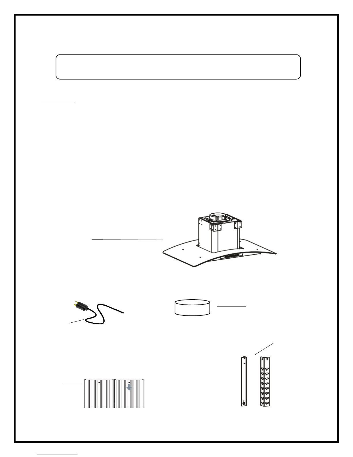
A. Range Hood
B. Power Cord (attached to range hood)
C. 6” or 8” round vent air flap depending on model (attached to range hood on top of unit)
D. Aluminum or Stainless Steel Filter(s) (attached to the bottom of the range hood)
E. (8) Support frame brackets. (4) upper and (4) lower
F. (1) 6” or 8” round flexible duct exhaust hose depending on model
G. (4) Phillips #10 X 2-3/8 Screw (expandable caps not to be used in some models)
H. (2) Stainless Steel Ducts (inner and outer)
I. (66-70) #6 X 3/8 SM Screw. Quantity will vary by model
J. (1) Ceiling mounting bracket to support either 6” or 8” flexible duct exhaust hose depending on model
K. (1) Grease collection tray. Will be preinstalled if the model purchased comes with a tray. Not all models
contain a grease collection tray.
B
A
C
D
E
Upper
Lower

7
Parts not supplied
➢Duct tape
➢Preinstalled ventilation system and ductwork
➢Preinstalled outside duct cap or weatherproofing
Installing the range hood
This installation is for mounting the product to a ceiling. Ensure your ceiling has the proper support to
hold the range hood weight. These instructions are general guidelines, please consult professional
installation specialist regarding the best type of mounting hardware and support system based on
your ceiling construction. All island range hoods must be installed and supported by studs and joists in
your ceiling. All homes constructions are different and installations will vary.
1. Begin installation by removing the filters (D) and removing any tape on the air flow flappers (C).
2. Remove protective film from range hood and ducting. When handling the ducting please wear protective
gloves to avoid sharp edges.
3. If your model has an electronic touch sensor control panel, remove the protective plastic film covering the
control panel.
F
G
H
I
J
Inner
Outer
K

8
4. Find the center of the ceiling where you are installing the range hood and trace a 6” or 8” circle depending on
model. You can use the ceiling mounting bracket (J) to help trace your cut out mark. The ceiling mounting
bracket is larger than the 6” and 8” opening needed. Ensure there are no studs where the opening is being
made.
5. After tracing the cutout circle, using a sabre saw or jig saw, cut out the drywall.
6. This island range hood must be supported to the ceiling studs or joists. Create two wooden support braces
and slide up through cut out hole in ceiling. Place the support braces on top of the studs or joist. The bottom
of the support braces need to align with the four holes on the mounting bracket.
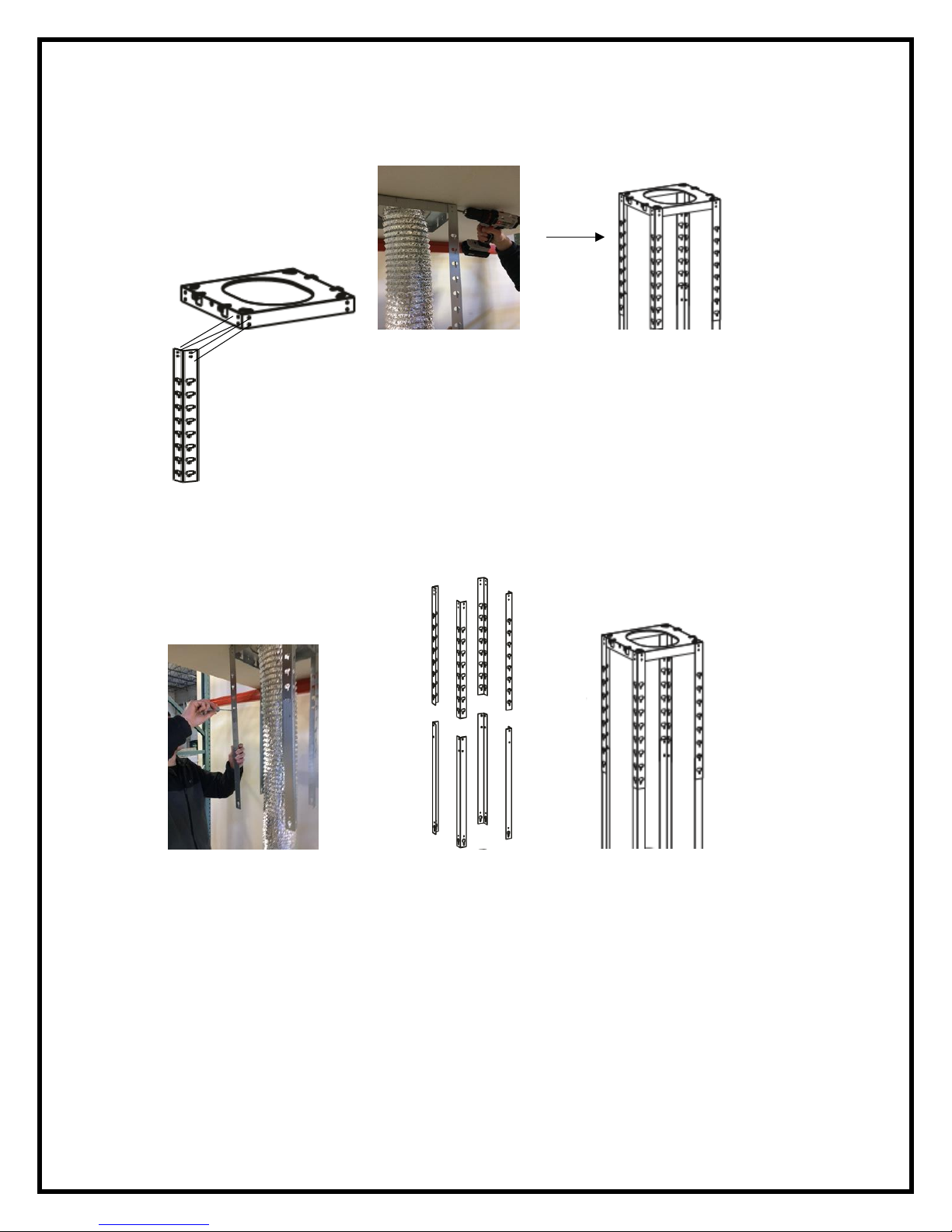
7. Attach the ceiling mounting bracket using the (4) Phillips #10 X 2-3/8 Screws through the mounting bracket
openings as shown below (the supplied screws may not work with all installations, please check with your
installation professional). The screws must enter the wooden support braces. While screwing into the
Mounting
bracket holes

9
support brace, reach your hand through the ceiling hole and hold the support brace in place. You may wish
to further brace the wooden support braces to the joist by entering your ceiling and adding additional
screws.
8. Install the 6” or 8” round flexible duct exhaust hose depending on model. Assemble ventilation to outside
ducting using duct tape and/or strapping. Note: If you are choosing the ductless/recirculating mode do not
install the duct exhaust hose.
Front of range hood
10
9. Attach the (4) upper support frame brackets (E) to the ceiling mounting bracket (J). Each support bracket will
use (4) #6 X 3/8 SM Screws (I).
10. Measure the distance that the bottom of the range hood will be from the top of your range (see page 5 for
reference). Attach the (4) lower support frame brackets (E) to the upper support frame brackets (E). Each
support bracket will use (4) #6 X 3/8 SM Screws (I).
11. Some models will come with one-piece seamless stainless-steel ducting versus the two-piece seamed
stainless-steel ducting as shown below:
This manual suits for next models
6
Table of contents
Other Winflo Ventilation Hood manuals


