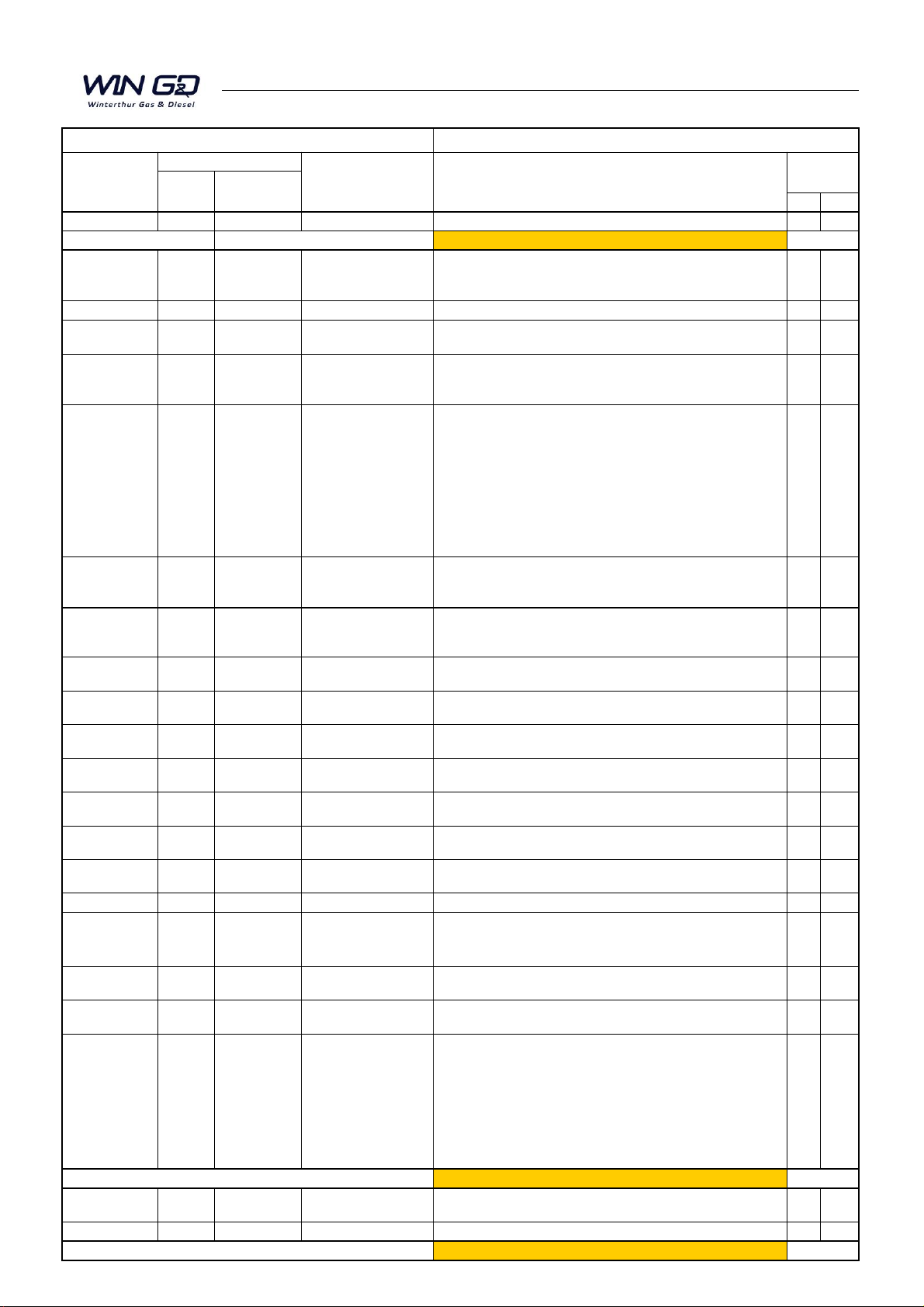
WinGD RT-flex50DF User manual

Maintenance Manual
RT-flex50DF
Issue 003 2020-10
Winterthur Gas & Diesel Ltd. Schützenstrasse 3 Tel. +41 (0)52 264 8844
Winterthur Gas & Diesel AG P.O. Box 414, 8401 Fax +41 (0)52 264 8866
Winterthur Gas & Diesel S.A. Winterthur, Switzerland www.wingd.com

© 2020-10 Winterthur Gas & Diesel Ltd. – All rights reserved
No part of this publication may be reproduced or copied in any form or by any means (electronic,
mechanical, graphic, photocopying, recording, taping or other information retrieval systems)
without the prior written permission of the copyright holder. Winterthur Gas & Diesel Ltd. makes
no representation, warranty (express or implied) in this publication and assumes no responsibility
for the correctness, errors or omissions of information contained herein. Information in this
publication is subject to change without notice.
NO LIABILITY, WHETHER DIRECT, INDIRECT, SPECIAL, INCIDENTAL OR CONSEQUENTIAL, IS
ASSUMED WITH RESPECT TO THE INFORMATION CONTAINED HEREIN. THIS PUBLICATION IS
INTENDED FOR INFORMATION PURPOSES ONLY.
www.wingd.com

Summary for Maintenance Manual
(MM)
Page No. Title Subject
Date No.
new exch.
2015 Maintenance Manual, Issue 2015 x
Date of publication 2015-03-31
0002-1/A1 2015-09 Table of Contents
New documents added: 0008-1/A2, 0803-1/A2, 2124-
1/A2,5555-1/A1, 6420-2/A1, 6545-2/A1, 6606-2/A1, 6708-2/A1,
9258-1/A1
x
0,2,5,6,9 Index (groups) x
0008-1/A2 2015 EAAD086011
Engine Numbering and
Designation
New dokument added x
0352-1/A1
(1,3,7)
2015-09 EAAD085996 Tightening Instruction
The text 'Never Seez NSBT8' changed to 'Never Seez
REGULAR GRADE'; Torque value for injection valve group
2722 and pilot injection valve group 2790 added
x
0360-1/A1 EAAD085476 Masses
Groups: 3310, 6506, 6606, 7206: the weight of the bearing
shell crank pin, SAC A44-SD, ABB-A175, cylinder lubrication
pump added; group 2124: weigh of the cylinder liner GAV50
Mk2 added; group 2708: weight of the cylinder cover with
exhaust valve changed; group 3122: weight of the flywheel
changed and values added; group 3310: weight of the bearing
shell crank pin changed; group 3403: weight of the piston two-
part complete, piston head and piston rod changed;
x
0803-1/A2 2015 EAAD086011
Engine Cross Section
and Longitudinal
Section
New dokument added x
2140-1/A1 2015-09
EAAD085685
EAAD085873
Gas Admission Valve
New dismantling and assembling tool replaced the old design;
paragraph 4 and 5 added
x
2140-1/A2 2015 EAAD085774 Gas Admission Valve New gas admission valve GAV50-Mk2 added x
2722-1/A1 2015-09 Injection Valve Information about terminal box addded. x
3403-1/A1
(4,7,8,9)
EAAD085973 Piston
Fig. 'M' to 'S' and 'U' changed, description with the new lifting
tool updated
x
5555-1/A1 2015 Pilot Fuel Supply Unit
Document moved from group 8 to group 5 and changed the
name
x
6420-2/A1 EAAD085839 Scavenge Air Receiver New document added (turbocharger at exhaust side); x
6545-2/A1 EAAD085896 Auxiliary Blower New document added (turbocharger at exhaust side); x
6606-2/A1 EAAD085896 Scavenge Air Cooler
Instruction for removal and installation of SAC A44-SD (7Cyl.),
turbocharger at exhaust side) added
x
6708-2/A1 Water Separator New document added (turbocharger at exhaust side); x
8733-1/A1 (2,3) 2015-09
EAAD085458
EAAD085477
HP Injection Pipe
Information about corerct installation of the claw added;
grinding tool with the new template added and replaced the old
one
x
8790-1/A1
HP Fuel Pipe Pilot
Valve
The title and content changed to HP pipe pilot fuel x
9258-1/A1 2015 EAAD085973
Sensor Cylinder
Pressure
New document added x
9403-5/A1
(3,4,5,11,16,
22,31,33,35,37)
2015-09
EAAD085973
EAAD085996
EAAD085896
Tool List
Tools: 94017-002, 94018-003, 94022H, 94023A, 94048-M30,
94653A-A175, 94656A, 94656B, 94661-IL, 94663-IL, 94663A-
IL, 94663B-IL, 94663C-IL, 94663D-IL, 94663E-IL, 94663F-IL,
94664-IL, 94667E,94667F,94667G,94667H, 94667I, 94890
added; New design of 94214 replaced the old one; tool 94272
newly defined; new lifting tool 94341 replaced the existing tool;
illustration and dimention changed; pages added and
renumbered
x
Date of publication 2015-11-03
0380-1/A1 2016 maintenance intervals major rework of the whole maintenance list x
whole book 2016 Maintenance Manual New Layout x
Date of publication 2016-04-11
Manual
Modification Service
Engine Documentation
RT-flex50DF
Modification
Page or
1/3 19/03/2018

Summary for Maintenance Manual
(MM)
Page No. Title Subject
Date No.
new exch.
Manual
Modification Service
Engine Documentation
RT-flex50DF
Modification
Page or
Group 5 ToC 2018-01 WinGD input ToC 5555-2/A1 added x
2140-2/A1 2017-12
Update
WinGD
Exhaust Valve:
Disassemble and
Assemble
Pge 7: Para 5, Steps 10 to 12 changed. x
2751-2/A1 2017-12 WinGD input
Exhaust Valve:
Disassemble and
Assemble
Page 6: Procedure changed, x
Date of publication 2018-01-23
0330-1/A1 2018-02 WinGD Input Group 5 ToC Page 21: Note added x
Group 2 ToC 2018-02 EAAD087460 Group 5 ToC
New documents added to ToC (2708-4/A1, 2708-5/A1 and
2708-6/A1)
x
2138-1/A1 2018-02 WinGD Input Lubricating Quill
Pge 1: Dismantling tool 94213 added to tool list. Pge2:
Replace procedure added.
x
2140-1/A1 2018-02 WinGD Input Gas Admission Valve Pge 7. Steps 10 to 14 changed. x
2708-4/A1 2018-02 EAAD087460
Sealing Face for the
Pilot Injection Valve
Position - Grind
New procedure x
2708-5/A1 2018-02 EAAD087460
Sealing Face for the
Fuel Injection Valve
Position - Grind
New procedure x
2708-6/A1 2018-02 EAAD087460
Sealing Face for the
Prechanmber - Grind
New procedure x
2751-1/A1 2018-02
Customer
input
Exhaust Valve:
Replacement of
Elastic Studs
Pge 6: Fig. 10 - Flow direction changed. x
2751-2/A1 2018-02 WinGD Input
Exhaust Valve:
Disassemble and
Assemble
Pge 7: Steps 6 to 10 changed. x
2790-1/A1 2018-02 WinGD Input
Pilot Injection Valve:
Removal,
Disassemble, Check,
Assemble, Installation
Pge 1: ToC changed. Pge 2: Procedure changed. Pge 5: data
added. Pge 7: Data added,
x
2722-1/A1 2018-02 WinGD Input
Injection Valve:
Removal and
Installation
Pge 3: Warning about copper paste added x
2722-2/A1 2018-02 WinGD Input
Injection Valve:
Disassemble, Checks,
Assemble
Pge 7: Warning about copper paste added x
Group 5 ToC 2018-02 WinGD Input Group 5 ToC
Pilot Fuel Supply Pump: Removal and Installation 5555-2/A1
inserted. Fuel Pressure Control Valve: Manual Release Valve -
Clean 5562-1/A2 inserted.
x
5552-5/A1 2018-02 Wartsila Input
Lubrication of Supply
Unit during
Maintenance
Procedure changed. New illustration added. x
5555-2/A1 2018-02 WinGD Input Group 5 ToC
New documemnt: Pilot Fuel Supply Pump: Removal and
Installation 5555-1/A1
x
5562-1/A2 2018-02 WinGD Input
Fuel Pressure Control
Valve: Manual
Release Valve - Clean
New procedure. x
9403-3/A1 2018-02 Wartsila Input
Hydraulic Pre-
tensioning Jacks
Pges 3 to 11: Sealing kits added. x
2/3 19/03/2018

3/3 01/10/2020
Modification Service
Engine Documentation
RT-flex50DF
Summary for Maintenance Manual
Page No.
Modification
Title
Subject
Page or
Manual
Date
No.
new
exch.
9403-5/A1
2018-02
WinGD Input
and
EAAD087159
Tools List
Page 38: 94844 Lubrication device added, Pge 37: Tool 94929
move to Special Recommended Tools on Pge 42. Pge 17:
Assembly tool 94289E added. Pge 18: New tools 94270-02,
94270-1 and 94270-3 added. Pge 37: Tool 94930 added.
x
Date of publication 2018-02
5583-1/A1
2020-05
WinGD Input
Fuel Pump Actuator:
Connection to Fuel
Pump
New document
x
5612-1/A1
2020-05
WinGD Input
Exhaust Valve Control
Unit − Pilot valve:
Removal and
Installation
Procedure updated
x
Group 5 ToC
2020-05
WinGD Input
Group 5 ToC
Fuel Pump Actuator: Connection to Fuel Pump added
x
6606-1/A2
2020-05
WinGD Input
Scavenge Air Cooler-
Cleaning instructions
New document
x
Group 6 ToC
2020-05
WinGD Input
Group 6 ToC
Scavenge Air Cooler- Cleaning instructions added
x
2722-1/A2
2020-05
WinGD Input
Injection Valve
Installation of Injection
Valve with FAST
New document
x
Group 2 ToC
2020-05
WinGD Input
Group 2 ToC
Injection Valve: Installation of Injection Valve with FAST added
x
9403-5/A1
2020-05
WinGD Input
Tools List
Page 8: Dismantling Tool added, Page 15: KF 94124 Support
added, Page 19: KF 94153 Cleaning Tool added, Page 25: KF
94156 & KF 94157 Fitting and dismantling device added, Page
29: KF 94216 Assembly Tool added, Page 32: KF 94239 Screw
plug G ½” added, Page 33: KF 94242 Lifting eye bolt added
x
Cover page
2020-05
WinGD Input
Cover page
New Cover Page Updated
x
Rear page
2020-05
WinGD Input
Rear page
New Rear Page Added
x
Logo change
2020-05
WinGD Input
Logo change
Logo is updated from Wärtsilä to WinGD
x
Date of publication 2020-05
0330-1/A1
2020-10
WinGD Input
Clearance Table –
Piston Rod Gland
Page 10: Illustration updated to include the scrapper ring
x
Date of publication 2020-10

0
1
2
3
4
5
6
7
8
9
MM / RT−flex / Register
Driving Wheels and Shut-off Valve for Starting Air
Crankshaft, Connecting Rod and Piston
Cylinder Liner and Cylinder Cover
Bedplate and Tie Rod
General Information
Supply Unit, Injection and Exhaust Valve Control
Scavenge Air Receiver and Auxiliary Blower
Cylinder Lubrication
Piping
Crank Angle Sensor Unit, Tools

Maintenance TOC
Table of Contents
RT-flex50DF
2016
Winterthur Gas & Diesel Ltd. 1/ 4
Table of Contents
General Information Group 0
For Particular Attention 0000−1/A1..................................................................
Preface 0001−1/A1.................................................................................
Engine Numbering and Designations (Turbocharger at Aft End) 0008−1/A1............................
Engine Numbering and Designations (Turbocharger at Exhaust Side) 0008−1/A2.......................
General Guidelines
for Maintenance: Safety Measures and Warnings 0011−1/A1........................................
for Lifting Tools: Wire Rope Slings, Span-sets, Eye Bolts, etc. 0012−1/A1.............................
Clearance Table 0330−1/A1.........................................................................
General Page 1...............................................................................
Crankshaft and Thrust Bearing 2, 3..............................................................
Crankshaft and Main Bearing 4, 5................................................................
Crosshead Guide 6, 7..........................................................................
Cylinder Liner 8, 9.............................................................................
Piston Rod Gland 10, 11........................................................................
Exhaust Valve 12, 13...........................................................................
Top and Bottom End Bearings to Connecting Rod 14, 15............................................
Piston Cooling and Crosshead Lubrication 16, 17..................................................
Piston and Piston Rings 18, 19..................................................................
Driving Wheels for Supply Unit 20, 21............................................................
Supply Unit 22, 23.............................................................................
Fuel Pump 24, 25..............................................................................
Tightening Values of Important Screwed Connections 0352−1/A1
..............................
Torque Values −Standard Screws and Elastic Studs 0352−2/A1.......................................
Masses (Weights): Individual Components per Piece in kg 0360−1/A1.................................
Maintenance Schedule: Inspection and Overhaul Intervals (Guidelines) 0380−1/A1.....................
Engine Cross Section and Longitudinal Section (TC at Driving End) 0803−1/A1........................
Engine Cross Section and Longitudinal Section (TC at Exhaust Side) 0803−1/A2.......................
Bedplate and Tie Rod Group 1
Bedplate and Thrust Bearing: Foundation Bolts −Check 1112−1/A1...................................
Main Bearing
Waisted Studs −Loosen and Apply Tension 1132−1/A1.............................................
Main Bearing −Removal and Installation 1132−2/A1...............................................
Thrust Bearing
Axial Clearance −Checks 1203−1/A1.............................................................
Thrust Bearing Pads −Removal and Installation 1224−1/A1.........................................
Winterthur Gas & Diesel Ltd. RT−flex50DF / MM / 2020

MaintenanceTOC
Table of Contents
RT-flex50DF
2016 2/ 4 Winterthur Gas & Diesel Ltd.
Engine Stays with Friction Shims: Tension −Checks 1715−1/A1......................................
Hydraulic Engine Stays: Oil Pressure Checks 1715−1/A2.............................................
Tie Rod: Tension Checks and Replacement Procedure 1903−1/A1.....................................
Cylinder Liner and Cylinder Cover Group 2
Cylinder Liner
Measure the Cylinder Liner 2124−1/A1...........................................................
Removal and Installation 2124−2/A1.............................................................
Remove Unwanted Material, Dress the Lubricating Grooves and Scavenge Ports 2124−3/A1............
Lubricating Quill: Removal and Installation 2138−1/A1...............................................
Gas Admission Valve GAV50: Removal, Disassemble, Checks, Assemble, Installation 2140−1/A1.......
Piston Rod Gland: Removal, Disassemble, Measure Worn Parts, Assemble, Installation 2303−1/A1......
Cylinder Cover
Cylinder Cover and Water Guide Jacket −Removal and Installation 2708−1/A1........................
Cylinder Cover Elastic Studs −Loosen and Apply Tension 2708−2/A1................................
Machining of Sealing Face for Injection Valve 2708−3/A1............................................
Sealing Face for the Pilot Injection Valve Position −Grind 2708−4/A1................................
Sealing Face for the Fuel Injection Valve Position −Grind 2708−5/A1................................
Sealing Face for the Prechamber −Grind 2708−6/A1..............................................
Injection Valve: Removal and Installation 2722−1/A1.................................................
Injection Valve: Checks, Disassemble, Assemble 2722−2/A1.........................................
Injection Valve: Installation of Injection Valve with FAST 2722−1/A2...................................
Starting Air Valve: Removal, Disassemble, Grind, Assemble, Installation 2728−1/A1....................
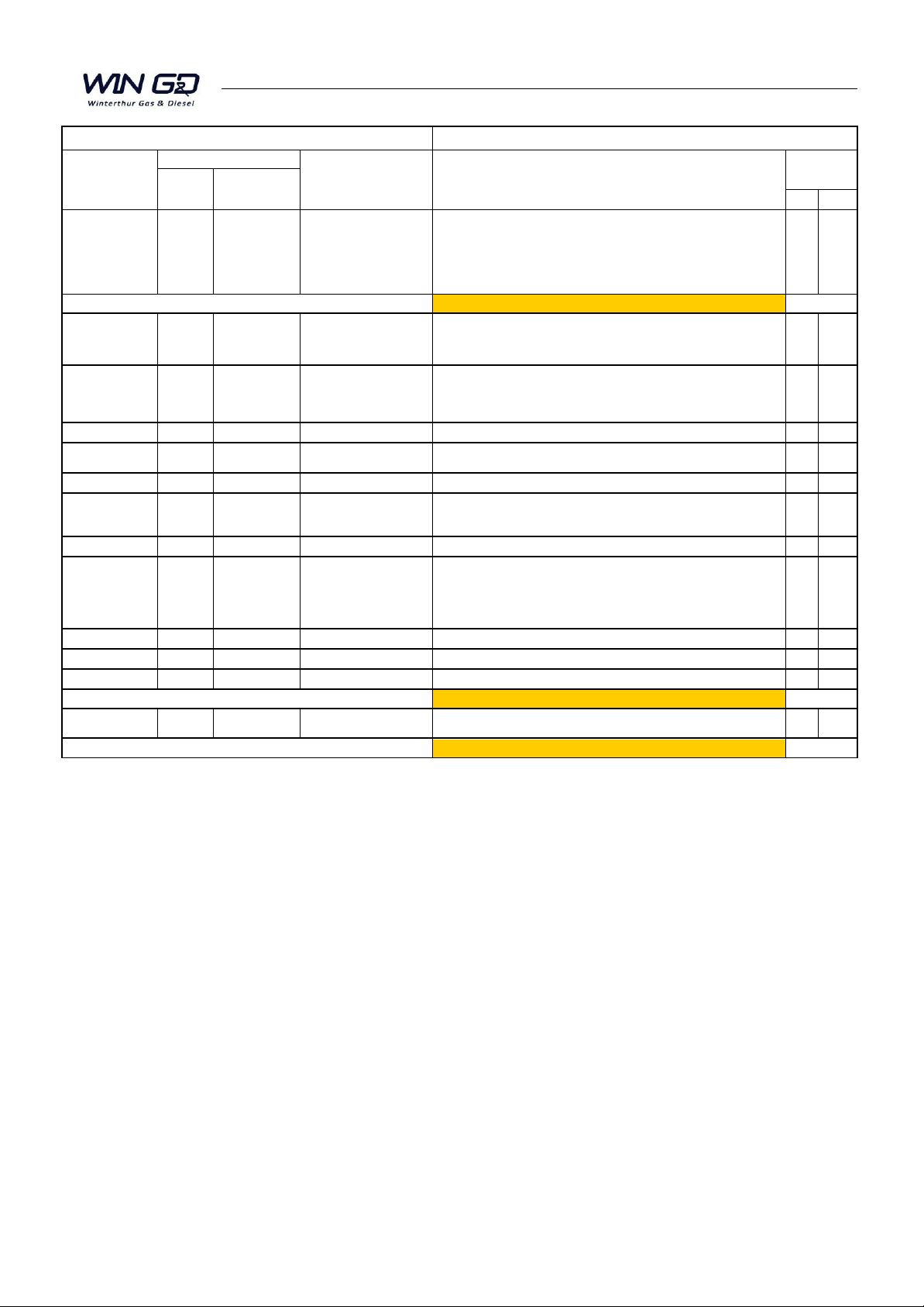
Exhaust Valve
Removal and Installation of Exhaust Valve, Replacement of Elastic Studs 2751−1/A1...................
Disassemble and Assemble 2751−2/A1...........................................................
Replacing and Grinding the Valve Seat 2751−3/A1.................................................
Grinding the Seating Surface on the Valve Head 2751−4/A1.........................................
Pilot Injection Valve: Removal, Disassemble, Check, Assemble, Installation 2790−1/A1.................
Crankshaft, Connecting Rod and Piston Group 3
Crankshaft: Crank Deflection −Measure 3103−1/A1.................................................
Vibration Damper
Inspection (GEISLINGER Vibration Damper) 3130−1/A1............................................
Axial Damper: Disassemble and Assemble 3140−1/A1................................................
Turning Gear: Teeth and Screwed Connections Check 3206−1/A1.....................................
Crankcase: Work Platform 3301−1/A1..............................................................
Top Platform: Configuration of Lifting Tools 3301−2/A2...............................................
Winterthur Gas & Diesel Ltd.RT−flex50DF / MM / 2020

Maintenance TOC
Table of Contents
RT-flex50DF
2016
Winterthur Gas & Diesel Ltd. 3/ 4
Connecting Rod
Loosening and Tensioning the Connecting Rod Studs 3303−1/A1....................................
Bottom End Bearing −Removal, Inspection and Installation 3303−2/A2...............................
Top End Bearing −Removal and Installation 3303−3/A2.............................................
Removal and Installation 3303−4/A2..............................................................
Top End Bearing −Bearing Cover Removal and Installation 3303−5/A2...............................
Crosshead
Clearances 3326−1/A1.........................................................................
Crosshead Pin −Removal and Installation 3326−2/A2..............................................
Piston
Removal and Installation 3403−1/A1..............................................................
Changing the Compression Shims 3403−2/A1.....................................................
Disassemble and Assemble 3403−3/A1...........................................................
Top Surface Check 3403−4/A1...................................................................
Piston Rings and Ring Grooves: Rate of Wear 3425−1/A1.............................................
Piston Cooling and Crosshead Lubrication: Inner Pipe −Removal and Installation 3603−1/A1...........
Driving Wheels and Shut-off Valve for Starting Air Group 4
Driving Wheels
Running and Backlash Clearances and Tooth Condition 4103−1/A1..................................
Starting Air Shut-off Valve: Clean and Function Check 4325−1/A1.....................................
Supply Unit, Injection and Exhaust Valve Control Group 5
Supply Unit
Servo Oil Pump and Servo Oil Pump Drive −Removal and Installation 5552−1/A1.....................
Camshaft and Bearing Shells −Removal and Installation 5552−2/A1.................................
Gear Wheel on Camshaft −Removal and Installation 5552−3/A1....................................
Supply Unit Removal and Installation 5552−4/A1...................................................
Lubrication of Supply Unit During Maintenance 5552−5/A1..........................................
Pilot Fuel Supply Unit: Lubrication 5555−1/A1.......................................................
Pilot Fuel Pump: Removal and Installation 5555−2/A1...............................................
Fuel Pump: Removal, Disassemble, Assemble, Installation 5556−1/A1................................
Fuel Pressure Control Valve: Removal, Check, Installation 5562−1/A1.................................
Fuel Pressure Control Valve: Manual Release Valve −Clean 5562−1/A2................................
Fuel Overpressure Safety Valve: Checks and Setting 5562−2/A1......................................
Flow Limiting Valve: Replacement 5562−3/A1........................................................
Fuel Pump Actuator: Connection to Fuel Pump 5583−1/A1...........................................
Exhaust Valve Control Unit: Removal, Disassemble, Assemble and Installation, 5612−1/A1.............
Winterthur Gas & Diesel Ltd. RT−flex50DF / MM / 2020

MaintenanceTOC
Table of Contents
RT-flex50DF
2016 4/ 4 Winterthur Gas & Diesel Ltd.
Regulating Linkage
Adjustment: Heinzmann StG 10-01 Actuator 5801−1/A1.............................................
Scavenge Air Receiver and Auxiliary Blower Group 6
Scavenge Air Receiver: Clean and do Checks 6420−1/A1.............................................
Scavenge Air Receiver (TC at Exhaust Side): Clean and do Checks 6420−2/A1.........................
Auxiliary Blower: Maintenance 6545−1/A1...........................................................
Auxiliary Blower (TC at Exhaust Side): Maintenance 6545−2/A1.......................................
Scavenge Air Cooler: Removal and Installation 6606−1/A1............................................
Scavenge Air Cooler: Cleaning Instructions 6606−1/A2...............................................
Scavenge Air Cooler (TC at Exhaust Side): Removal and Installation 6606−2/A1........................
Water Separator: Removal and Installation 6708−1/A1................................................
Water Separator Removal and Installation (TC at Exhaust Side) 6708−2/A1............................
Cylinder Lubrication Group 7
Cylinder Lubricating System 7218−1/A1............................................................
Piping Group 8
Exhaust Waste Gate (Low-load Tuning)8135−1/A1.............................................
HP Servo Oil Pipe: Removal, Grind, Installation 8447−1/A1.......................................
Hydraulic Pipe for Exhaust Valve Drive: Removal, Grind, Installation 8460−1/A1........................
HP Injection Pipe: Removal, Grind, Installation 8733−1/A1.........................................
HP Fuel Pipe: Removal, Grind, Installation (TC at Aft End) 8752−1/A1.................................
HP Pipe Pilot Fuel: Removal and Installation 8790−1/A1..............................................
Crank Angle Sensor Unit, Tools Group 9
Crank Angle Sensor Unit: Proximity Sensor −Replace 9223−1/A1..................................
Cylinder Pressure Sensor: Removal and Installation 9258−1/A1.......................................
Tools: Description 9403−1/A1.......................................................................
Hydraulic Jacks and Pumps: Configuration 9403−2/A1...............................................
Hydraulic Pre-tensioning Jacks
Storage, Servicing and Maintenance 9403−3/A1...................................................
General Application Instructions 9403−4/A1.......................................................
Tool List 9403−5/A1................................................................................
Standard Tools Pages 1 to 43...................................................................
Recommended Special Tools Pages 44 to 45......................................................
Winterthur Gas & Diesel Ltd.RT−flex50DF / MM / 2020

Maintenance Group0
Winterthur Gas & Diesel Ltd. 1/ 1
General Information Group 0
For Particular Attention 0000−1/A1..................................................................
Preface 0001−1/A1.................................................................................
Engine Numbering and Designations (Turbocharger at Aft End) 0008−1/A1............................
Engine Numbering and Designations (Turbocharger at Exhaust Side) 0008−1/A2.......................
General Guidelines
for Maintenance: Safety Measures and Warnings 0011−1/A1........................................
for Lifting Tools: Wire Rope Slings, Span-sets, Eye Bolts, etc. 0012−1/A1.............................
Clearance Table 0330−1/A1.........................................................................
General Page 1...............................................................................
Crankshaft and Thrust Bearing 2, 3..............................................................
Crankshaft and Main Bearing 4, 5................................................................
Crosshead Guide 6, 7..........................................................................
Cylinder Liner 8, 9.............................................................................
Piston Rod Gland 10, 11........................................................................
Exhaust Valve 12, 13...........................................................................
Top and Bottom End Bearings to Connecting Rod 14, 15............................................
Piston Cooling and Crosshead Lubrication 16, 17..................................................
Piston and Piston Rings 18, 19..................................................................
Driving Wheels for Supply Unit 20, 21............................................................
Supply Unit 22, 23.............................................................................
Fuel Pump 24, 25..............................................................................
Tightening Values of Important Screwed Connections 0352−1/A1
..............................
Torque Values −Standard Screws and Elastic Studs 0352−2/A1.......................................
Masses (Weights): Individual Components per Piece in kg 0360−1/A1.................................
Maintenance Schedule: Inspection and Overhaul Intervals (Guidelines) 0380−1/A1.....................
Engine Cross Section and Longitudinal Section (TC at Driving End) 0803−1/A1........................
Engine Cross Section and Longitudinal Section (TC at Exhaust Side) 0803−1/A2.......................
Winterthur Gas & Diesel Ltd. RT−flex50DF / MM / 2016

Maintenance 0000−1/A1
Winterthur Gas & Diesel Ltd. 1/ 1
For Your Attention
1. General
This manual is for the operator and is for use only for the related type of diesel engine
(the engine described in this manual). The data in this manual is confidential.
Make sure that you read carefully the Operation Manual before you operate the
engine.
Make sure that you know the Inspection and Overhaul intervals in the Maintenance
Manual before you operate the engine.
Make sure that you read the data in Group 0 in the Maintenance Manual before you
do maintenance work on the engine.
2. Spare Parts
Use only original spare parts and components to make sure that the engine will
continue to operate satisfactorily. All equipment and tools for maintenance and
operation must be serviceable and in good condition.
The extent of all supplies and services is set exclusively to the related supply
contract.
3. Data
The specifications and recommendations of the classification societies, which are
essential for the design, are included in this manual.
The data, instructions, graphics and illustrations etc. in this manual are related to
drawings from Winterthur Gas & Diesel Ltd. These data relate to the date of issue of
the manual (the year of the issue is shown on the title page). All instructions, graphics
and illustrations etc can change because of continuous new development and
modifications.
4. Personnel
Only qualified personnel that have the applicable knowledge and training must do
work on the engine, its systems and related auxiliary equipment.
Data related to protection against danger and damage to equipment are specified in
this manual as Warnings and Cautions.
2016

Intentionally blank

Maintenance 0001−1/A1
Winterthur Gas & Diesel Ltd. 1/ 1
Preface
The instructions in this Maintenance Manual are to help make sure that maintenance
is done correctly at the specified intervals.
It is a condition that the personnel who do important work have the applicable training
and experience.
Data about the operation of the engine and descriptions of the function of the different
systems are part of the Operation Manual. Chapter 0010−1 in the Operation Manual,
gives descriptions about the Operation and Maintenance Manuals and data about
symbols, signs and special characters.
More instructions about the operation and maintenance of components from
sub-suppliers are found in the instruction leaflets of the related manufacturers (for
example, engine components, tools or devices that are not manufactured in
accordance with production drawings from Wärtsilä Switzerland Ltd).
The Maintenance Manual has the primary data that follow:
DGeneral Guidelines for Maintenance. These give recommendations about
precautions and applicable procedures.
DClearance tables, tightening values of screwed connections, masses (weights).
These give data about usual and maximum permitted clearances, engine
components, type and use of different sealing rings etc.
DMaintenance Schedule. This schedule shows the nominal intervals when the
different maintenance operations must be done during standard operation
conditions.
DDesign Groups give the instructions and procedures for maintenance work on
specified engine parts.
DTool Lists give data about the applicable tools and devices necessary to do the
maintenance work. The tools and devices are usually supplied wit the engine.
All data in this manual (text and illustrations) are correct at the date of issue.
Modification of data is done regularly.
2016

Maintenance 0008−1/A1
Winterthur Gas & Diesel Ltd. 1/ 2
General Configuration −Turbocharger at Aft End
FREE ENDDRIVING END
Thrust Bearing Pads
FUEL SIDE EXHAUST SIDE
Rail Unit
Clockwise Rotation
Counterclockwise
Rotation
Supply Unit
Turbocharger
Cylinder
Number
Auxiliary
Blower 1
654327
1 2 3 4 5
WCH002808
Main Bearing
Number
Auxiliary
Blower 2
1
DATA FOR
5 CYLINDERS
WCH002808
2016
General

Maintenance 0008−1/A2
Winterthur Gas & Diesel Ltd. 1/ 2
General Configuration −Turbocharger on Exhaust Side
DRIVING END
Thrust Bearing Pads
FUEL SIDE
Rail Unit
Clockwise Rotation
Counterclockwise
Rotation
Supply Unit
Turbocharger
Cylinder
Number
Auxiliary
Blower 1
6543
27
1 2 3 4 5
WCH03435
Main Bearing
Number
Auxiliary
Blower 2
1
DRAWN FOR
7 CYLINDERS
WCH03435
6 7
89
EXHAUST SIDE
DATA FOR ONE A175 TURBOCHARGER
FREE END
2016
General

Maintenance 0011−1/A1
Winterthur Gas & Diesel Ltd. 1/ 4
Safety Precautions and Warnings
1. General 1..........................................................
2. General Safety Precautions 1........................................
3. Precautions before the Start of Maintenance 2........................
4. Special Safety Procedures 3.........................................
5. Recommendations 4................................................
1. General
The maintenance, which must be done on the engine at regular intervals, is described
in the Maintenance Schedule 0380−1. The maintenance intervals are related to the
mode of operation, the power and the quality of the fuel used. For more data, refer to
the Maintenance Schedule.
The maintenance intervals can be extended or decreased.
Note: The recommendations related to safety procedures and maintenance
given below are mandatory. All other safety recommendations not given
here must also be obeyed.
2. General Safety Precautions
The general safety conditions are as follows:
DAll personnel must know the fire fighting procedures.
DAll personnel must know the health and safety data and environment protection
data related to the operation and maintenance of diesel engines.
DAll personnel must know the dangers, functions and operation of cranes and
lifting devices.
DThe safety officer must make sure that all precautions are done to prevent
dangerous conditions.
DThe operator must select a supervisor to give work tasks to each person who
does maintenance work.
DMake sure that fluids that drain or are released cannot cause explosions, fires or
accidents during maintenance. Keep the engine and the areas around the engine
clean to help prevent accidents and increase the quality of the work.
DBefore you start maintenance on the engine, make sure that if necessary, the
pressure in the related systems is released and fluids are drained. Make sure
that you record the pressures and quantities.
DSome media, e.g. fuel, oil are very flammable, thus you must keep such media
away from fire, hot parts etc.
DMake sure that personnel do not smoke in the engine room.
DTo prevent injury, make sure that all surfaces where personnel can walk or stay
do not have oil, fuel etc and are kept clean and dry.
General Guidelines for Maintenance
2016

Maintenance0011−1/A1
Winterthur Gas & Diesel Ltd.
2/ 4
3. Precautions before the Start of Maintenance
CAUTION
Damage Hazard: Do not use water or cleaning fluid to clean the
electronic components and control boxes on the engine and the
rail unit. Damage can occur if water or cleaning fluid goes into
these electronic components or control boxes.
CAUTION
Damage Hazard: When electrical welding is done near or on the
engine, electromagnetic fields or peak voltage can occur. This
can cause damage to the electronic components of the Engine
Control System.
Before you do electrical welding, you must do the procedure that follows:
1) Stop the engine.
2) Set to off the electronic system. After one minute, you can continue.
3) If the welding area is in a radius of two meters from an electronic module and/or
a sensor, disconnect the modules and/or sensors.
4) Close the covers of all electronic boxes and apply protection to the cables,
sensors, etc. to prevent damage from sparks and heat.
5) Use a conductive material connected to earth to give protection to the check and
control units.
6) Make sure that the welding cable goes directly to the welding point without
unnecessary loops. Also, make sure that the welding cables are not parallel to
cables of the electronic units.
Before you start the maintenance on the engine, specially the running gear, do the
procedure that follows:
1) Close the shut-off valves on the starting air bottles.
2) Close all the shut-off valves in the control air supply unit.
3) Open the drains on each starting air bottle to release all the pressure.
4) On the starting air shut-off valve, operate the handwheel to move the shut-off
valve to the position CLOSED.
5) On the main starting air pipe, open the vent and drain valve. Keep the vent and
drain valve in the open position until maintenance is completed.
6) On the starting air shut-off valve, open the vent valves. Keep the vent valves in
the open position until maintenance is completed.
7) Open all indicator valves on the cylinder covers. Keep the indicator valves in the
open position until maintenance work is completed.
8) Engage the turning gear and lock the lever. The gear pinion must be in the
engaged position.
Note: If the engine was stopped because the running gear or bearings have
become too hot, do not open the crankcase doors before an elapsed time
of 20 minutes.
Note: During all engine operations (short or usual), the crankcase doors must
be locked with the clamps.
Note: Where carbon dioxide (CO2) is used to extinguish a fire in the engine,
there is a risk of suffocation. Make sure that all related spaces have good
airflow to remove all CO2gas before
2016
Safety Measures and Warnings
Table of contents
Popular Industrial Equipment manuals by other brands

ABB
ABB HT564332 Operation manual

Mayr
Mayr ROBA-stop 820.61 Series Installation and operational instructions

ABB
ABB HT607824 Operation manual

Johnson Controls
Johnson Controls Frick ECH Installation operation & maintenance

Tesmec
Tesmec PT1250 Handbook

Siemens
Siemens LITHOSTAR Multiline Start-up instructions