Winpower DE20I4 User manual

INSTALLATION AND
OPERATIONS MANUAL
with STAMFORD
GENERATORS
MODELS:
DE20I4
DE30I4
DE45F4
DE65F4
DE90F4
MANUAL KEY START AND
DSE3110 ELECTRIC START
ELECTRIC START
DIESEL GENERATORS

SAVE THESE INSTRUCTIONS
This manual contains important instructions that should be fol-
lowed during installation and maintenance of the generator and
batteries.
Read and understand all instructions in the manual before starting
and operating the generator set.
USING THIS MANUAL
Congratulations on your choice of a WINPOWER generator set.
You have selected a high-quality, precision-engineered generator
set designed and tested to give you years of satisfactory standby
service.
To get the best performance from your new engine generator set,
it is important that you carefully read and follow the operating
instructions in this manual.
Should you experience a problem please follow the “Things To
Check” near the end of this manual. The warranty listed in this
manual describes what you can expect from WINPOWER should
you need service assistance in the future.
COPY YOUR MODEL AND SERIAL NUMBER HERE
No other WINPOWER generator has the same serial number as
yours. It is important that you record the number and other vital
information here. If you should ever need to contact us on this unit
it will help us to respond to your needs faster.
MODEL________________________________
SERIAL NUMBER________________________
‘M” Spec. ______________________________
PURCHASE DATE_______________________
DEALER_______________________________
TABLE OF CONTENTS
INTRODUCTION i
GUIDE TO PRODUCT SAFETY 1
BASIC INFORMATION 2
Specication Table 2
Description 3
RECEIVING THE GENERATOR 3
Unpacking the unit 3
ENGINE GENERATOR INSTALLATION
Installation 4
Engine Generator Set Mounting 5
Fuel Installation 5
Lubrication 6
Coolant 6
Battery Installation 6
Control Panel Wiring Diagram 8
AC Electrical Connection 9
Key Start Panel Layout 10
Manual Key Strt Up 10
DSE3110 Elcectronic Control 11
DSE3110 Start UP 13
DSE3110 Fault Codes 15
TROUBLESHOOTING INFORMATION 16
DC SCHEMATIC - WIRING DIAGRAM
MANUAL KEY START
DE20I4 & DE30I4 17
DE45I4 & DE65I4 18
DC SCHEMATIC - WIRING DIAGRAM DSE3110
DE20I4 & DE30I4 DSE 702 19
DE45I4 & DE65I4 DSE 702 20
AC WIRING - THREE PHASE
277/480 Volt 21
120/208 Volt 21
120/240 Volt 22
AC WIRING - SINGLE PHASE
120/240 Volt 22
GENERATOR TESTING RESISTANCES &
ENGINE REPLACEMNT PARTS. 23
REMOTE START WIRING 25
12 MONTH WARRANTY 26
PROPER USE AND INSTALLATION
You must be sure your new engine generator set is:
* Properly serviced before starting
* Operated in a well ventilated area
* Properly exhausted and gases safely dispersed
* Wired by a qualied electrician
* Operated only for its designed purposes
* Used only by operators who understand its operation
* Properly maintained

4094-00 60708-162
1
IMPORTANT SAFETY
INSTRUCTIONS
SAVE THESE INSTRUCTIONS
This manual contains important instructions that
should be followed during installation and maintenance
of the generator and batteries.
Read and understand all instructions in the manual
before starting and operating the generator set.
This engine generator set has been designed and
manufactured to allow safe, reliable performance. Poor
maintenance, improper or careless use can result in potential
deadly hazards; from electrical shock, exhaust gas asphyxiation,
or re. Please read all safety instructions carefully before
installation or use. Keep these instructions handy for future
reference. Take special note and follow all warnings on the unit
labels and in the manuals.
ANSI SAFETY DEFINITIONS
************************************************************
DANGER:
DANGER indicates an imminently hazardous situation which, if
not avoided, will result in death or serious injury. This signal word
is to be limited to the most extreme situations.
***********************************************************
************************************************************
WARNING:
WARNING indicates a potentially hazardous situation which, if
not avoided, could result in death or serious injury.
***********************************************************
***********************************************************
CAUTION:
CAUTION indicates a potentially hazardous situation which, if not
avoided, may result in minor or moderate injury. It may also be
used to alert against unsafe practices.
************************************************************
NOTE:
CAUTION is also used on the unit labels and in this manual
to indicate a situation that could result in serious damage or
destruction of the equipment and possible personal injury.
1. ELECTRIC SHOCK - The output voltage present in this
equipment can cause a fatal electric shock. This equipment
must be operated by a responsible person.
a. Do not allow anyone to operate the generator without
proper instruction.
b. Guard against electric shock.
c. Avoid contact with live terminals or receptacles.
d. Use extreme care if operating this unit in rain or snow.
e. Use only three-prong grounded receptacles and
extension cords.
f. Be sure the unit is properly grounded to an external
ground rod driven into the earth.
2. FIRE HAZARD - Diesel fuel presents a hazard of possible
explosion and/or re.
a. Do not smoke or use open ame near the generator
set.
b. Keep a re extinguisher nearby and know its proper use.
Fire extinguishers rated ABC by NFPA are appropriate.
3. DEADLY EXHAUST GAS - Exhaust fumes from any diesel
engine contain carbon monoxide, an invisible, odorless
and deadly gas that must be mixed with fresh air.
a. Operate only in well ventilated areas.
b. Never operate indoors.
c. Never operate the unit in such a way as to allow exhaust
gases to seep back into closed rooms (i.e. through
windows, walls or oors).
4. NOISE HAZARD - Excessive noise is not only tiring, but
continual exposure can lead to loss of hearing.
a. Use hearing protection equipment when working
around this equipment for long periods of time.
b. Keep your neighbors in mind when permanently install-
ing this equipment.
5. CLEANLINESS - Keep the generator and surrounding area
clean.
a. Remove all grease, ice, snow or materials that create
slippery conditions around the unit.
b. Remove any rags or other material that could create
potential re hazards.
c. Carefully wipe up any fuel or oil spills before starting the
unit.
d. Never allow leaves or other ammable material to build
up around the engine exhaust area.
6. SERVICING EQUIPMENT - All service, including the
installation or replacement of service parts, should be
performedonlybyaqualiedtechnician.
a. Use only factory approved repair parts.
b. Do not work on this equipment when fatigued.
c. Never remove the protective guards, cover, or recep-
tacle panels while the engine is running.
d. Use extreme caution when working on electrical compo-
nents. High output voltages from this equipment can
cause serious injury or death.
e. Always avoid hot mufers, exhaust manifolds, and
engine parts. They all can cause severe burns instantly.
f. Installing a generator set is not a “do-it-yourself” project.
Consult a qualied, licensed electrician or contractor.
The installation must comply with all national, state, and
local codes.
g. Always make sure unit is disabled before placing your
hands anywhere near the fan, belts, alternator or water
hoses.

60708-162 4094-00
2
TESTING POLICY:
Before any generator is shipped from the factory, it is fully
checked for performance. The generator is loaded to its
full capacity, and the voltage, current, and frequency are
carefully checked.
Rated output of the generators is based on engineering
tests of typical units, and is subject to, and limited by, the
temperature,altitude,fuel,andotherconditionsspeciedby
the manufacturer of the applicable engines.
NOTE:
These units come factory set for either key start or manual start.
With DSE 3110 controller used in the manual start option it is
possible to wire the control for remote start. See page 25 of this
manual for wiring instructions. The key start version does not
have this option.
SPECIFICATIONS
MODEL DE2014-3 DE20I4-4 DE20I4-17 DE20I4-18
Generator
Wattage 20000 20000 20000 20000
Volts 120/240 120/208 120/240 277/480
Phase single three three three
PF 1.0 .80 .80 .80
AMPs 83.0 69.5 60.2 30.1
Hertz 60 60 60 60
Engine
Model Isuzu 4LE1
Starting System 12 Volt Manual Start
Mufer Standard
Stop System Key/Emergency
Fuel Consumption (full Load) 1.8 Gal/hour
MODEL DE30I4-3 DE30I4-4 DE30I4-17 DE30I4-18
Generator
Wattage 30000 30000 30000 30000
Volts 120/240 120/208 120/240 277/480
Phase single three three three
PF 1.0 .80 .80 .80
AMPs 125 104 90 45
Hertz 60 60 60 60
Engine
Model Isuzu 4LE TurboCharged
Starting System 12 Volt Manual Start
Mufer Standard
Stop System Key/Emergency
Fuel Consumption (full Load) 2.6 Gal/hour
MODEL DE45F4-3DE45F4-4 DE45F4-17 DE45F4-18
Generator
Wattage 40000 45000 45000 45000
Volts 120/240 120/208 120/240 277/480
Phase single three three three
PF 1.0 .80 .80 .80
AMPs 166 156 135 68
Hertz 60 60 60 60
Engine
Model Iveco N45SM1
Starting System 12 Volt Manual Start
Mufer Standard
Stop System Key/Emergency
Fuel Consumption (full Load) 4.09 Gal/hour
MODEL DE65F4-3 DE65F4-4 DE65F4-17 DE65F4-18
Generator
Wattage 55000 62000 62000 62000
Volts 120/240 120/208 120/240 277/480
Phase single three three three
PF 1.0 .80 .80 .80
AMPs 229 215 186 93
Hertz 60 60 60 60
Engine
Model Iveco N45SM2 TurboCharged
Starting System 12 Volt Manual Start
Mufer Standard
Stop System Key/Emergency
Fuel Consumption (full Load) 4.57 Gal/hour
MODEL DE90F4-3 DE60F4-4 DE90F4-17 DE90F4-18
Generator
Wattage 86000 90000 90000 90000
Volts 120/240 120/208 120/240 277/480
Phase single three three three
PF 1.0 .80 .80 .80
AMPs 358 312 270 135
Hertz 60 60 60 60
Engine
Model Iveco N45TM2 TurboCharged
Starting System 12 Volt Manual Start
Mufer Standard
Stop System Key/Emergency
Fuel Consumption (full Load) 6.94 Gal/hour

4094-00 60708-162
3
INTRODUCTION AND
DESCRIPTION
PRODUCT DESCRIPTION:
This engine-generator set is designed for manual key start
operation. The engine-generator set is fully tested at the factory
prior to shipment to insure proper operation of each individual
component as well as the total system’s performance and
reliability.
The engine generator set consists of a multi-cylinder, liquid cooled
engine nominally operating at 1800 rpm. The generator frequency
regulation is maintained by the engine governor to within +/- 1.5
hertz (cps), from no load to rated load for standard mechanical
governors. The generator is a single bearing, direct drive, rotating
eld brushless design. The generator is connected to the engine
ywheel via exible drive disks. The Generator Set is skid
mounted with isolation mounts between the engine and base on
all units.
NOTICE:
These engine generator sets have only basic engine protections.
The Manual Key start panel only provides low oil pressure and
high coolant temperature protection, with no voltage or frequency
displays. The DSE 3110 electronic start panel displays a basic
voltage and frequency reading derived from a line to neutral
feed from the generator to the DSE 3110 control. Based on this
information it also provides basic over/under speed and voltage
protection. Low oil pressure and high water temperature reading/
shutdowns are provided by senders mounted on the engine. No
other control options are available on the DE Series Generators,
if you application requires additional safety devices or signals
consider upgrading to the DR Series Generators by WINPOWER.
A customer supplied 12 Volt battery is required to complete the
installation. Battery requirements are listed later under the battery
installation section.
These engine generator sets come standard with a manual key
start system. This key start system utilities a safety latching
relay that shut the unit down if the oil pressure gets low or water
temperature gets too high. The safety latching relay must be
depressed during cranking. Available as an option is a digital
DSE 3110 controller that is also programmed for electric start.
The DSE 3110 will electronically display your engine speed,
generator voltage, generator frequency, engine running time
and your battery level voltage. In addition it monitors your oil
pressure, water temperature, over/under speed and overcrank to
insure safe trouble free operation. Both systems are discussed
later in detail.
GENERATOR SET:
Every WINPOWER Generator Set has its own unique identity
data plate. This data plate identies the complete unit model
number, the system serial number and has links to the individual
components that form the generator set in our factory records.
Several of the major components also have their own individual
identity plates providing additional information to document build
data for warranty and replacement parts.
Be sure to have the main WINPOWER unit data plate information
recorded inside the front cover of this manual for future reference
and for identication whenever requesting eld or factory technical
assistance. Primary elds needed for assistance are complete
model number, serial number and especially the M-Spec number.
The M-Spec number (if provided) is recorded in the ‘TYPE NO.’
block on the lower right of the plate.
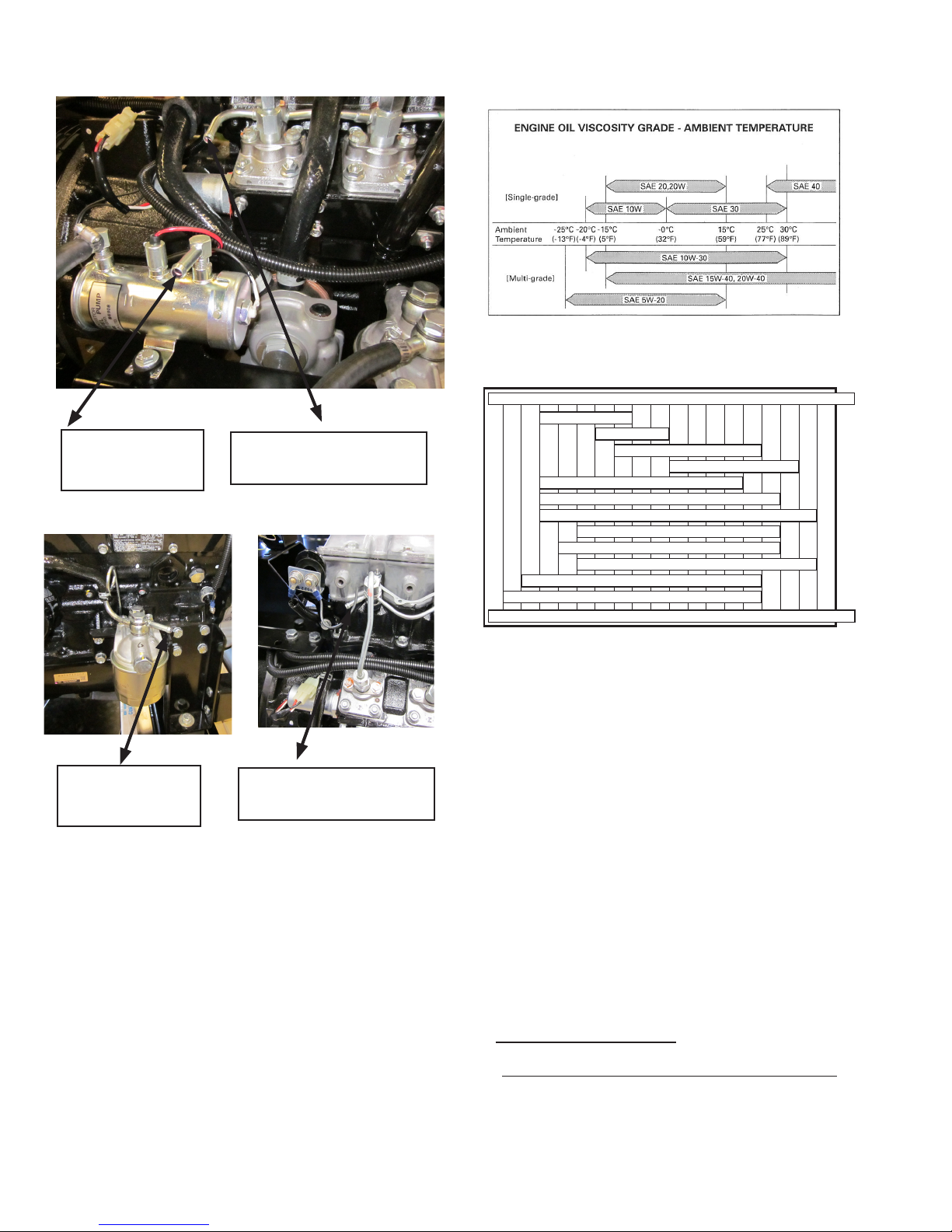
ENGINE:
This manual covers specic operation of the combined engine
generator set. Refer to engine operating and maintenance
instructions for specic instruction on the care and maintenance
of the engine. Oil and fuel requirements along with maintenance
schedules and engine warranty information are provided by the
individual engine manufacturers.
** CAUTION **
EQUIPMENT DAMAGE - Be sure to check the engine oil level
frequently as specied in the engine manual.
The engine manufacturer has established an excellent worldwide
engine service organization; engine service is available from a
nearby authorized dealer or distributor. Go to the WINCO web
site for a list of engine dealers. (http://www.wincogen.com/
Engine_Support/ )
The rated power of each engine-generator is limited by the
temperature, altitude and all other ambient conditions specied
by the engine manufacturer. Engine power will decrease 3-1/2%
for each 1000 ft. above sea level, and will decrease an additional
1% for each 10 degrees Fahrenheit above 60 degrees Fahrenheit.
Units should not be operated in ambient temperature greater than
125 degrees Fahrenheit.
GENERATOR:
WINPOWER Generator Sets use brushless, AVR (Auto-
Voltage Regulator) controlled broad-range generator ends. The
generator converts rotational mechanical energy into electrical
energy. These WINPOWER units are equipped with generators
manufactured by Cummins Stamford. Each generator ‘end’ has its
own data tag. A unique serial number is stamped on the data plate
and the data label is afxed to the main frame of the generator on
the left side.
RECEIVING THE GENERATOR
The generator set will generally be shipped by a commercial
‘common freight carrier’. Routing is determined by the bulk, size,
and a means available to unload the generator at the receiving
end. WINPOWER recommends units that are shipped by
common carrier be delivered to a commercial dock to allow the
Generator Set to be unloaded in a safe, efcient manner and to
minimize handling damage to the unit.
Locate the packing slip on the side of the crate or request it from
the truck driver. When receiving the generator take special care
in examining it for damage during shipment. Avoid signing for the
equipment until a full visual assessment and inventory have been
made. Verify that you have received the right equipment and the
proper amount by matching up the equipment to the packing list.

60708-162 4094-00
4
UNPACKING INSTRUCTIONS:
When unpacking the generator set, be sure to inspect it carefully
for freight loss or damage. If loss or damage is noted at the time
of delivery, require that the person making the delivery make note
of the loss or damage on the freight bill, or afx his signature
under the consignee’s memo of the loss or damage. Contact the
carrier for claim procedures.
When loss or damage is noted after delivery, segregate the
damaged material, and contact the carrier for claim procedures.
“Concealed Damage” is understood to mean damage to the
contents of a package which is not in evidence at the time of
delivery by the carrier, but which is discovered later. The carrier
or carriers are responsible for merchandise lost or damaged
in transit. The title to goods rests with the consignee when
generators are shipped fob factory, and only the consignee can
legally le a claim.
***** CAUTION ****
EQUIPMENT DAMAGE - These units are shipped with oil,
and a 50/50 mix of coolant. Be sure to check all uid
levels before operating. See engine manufacturer’s
instruction manual for recommended oil requirements
before initial starting.
UNPACKING:
(Not recommended until the unit is on-site)
1. Carefully remove the crate.
2. After inspecting the engine-generator for external physical
damage, locate and check the following items packed with
the unit.
a. Owner’s operators manual.
b. Engine manufacturer’s instruction manual.
c. Battery hold-down brackets & hardware.
d. Unit components or accessory items shipped loose
for on-site installation.
e. Optional accessories.
3. Remove main frame hold down bolts.
4. Unit can now be lifted from shipping rails.
LIFTING THE GENERATOR SET
NOTICE - Personal Injury
To prevent injury to persons or equipment, observe the
following guidelines when lifting the generator:
Due to the different designs, congurations, options, weights,
site conditions, and available material handling equipment,
specic lifting instructions are not provided for each individual
generator set model. General guidelines provided are applicable
to the entire standby generator line. It is the responsibility of the
installing party to follow the lifting equipment’s operators manual
to prevent injury to personnel and damage to the generator.
Smaller Generator Sets may not require use of overhead lifting
equipment and may be placed on the pad with basic material
handling equipment, i.e. a forklift.
CAUTION: - Do not attempt to lift the generator set by the means
of the lifting eyes on the engine or generator end.
These lifting points are only for use during the manufacturing
process and are designed for lifting of the individual Generator
Set component.
***************
***** WARNING ****
***************
NEVER - attempt to lift the fuel tank while lled with fuel.
Sloshing of the fuel can cause a shift in the balance of the
fuel tank, making for a DANGEROUS, unbalanced lifting load.
If the generator was shipped on the fuel tank, use the lifting
points located on the fuel tank to move the entire Generator
Set into place. DO NOT place fuel in the tank prior to lifting.
INSTALLATION
***************
***** WARNING ****
***************
PERSONAL INJURY - Before proceeding with the installation,
be sure the engine control is in the “stop” position. Before
proceeding with the installation, be sure the Generator MLCB
(Main Line Circuit Breaker) is in the ‘OFF’ position and the
unit starting battery is disconnected.
GENERAL INFORMATION
This series of engine/generator sets are designed and built as
open power units, meaning no weather protection has been
provided. These unit must be installed inside of an enclosure that
will provide proper protection from the elements.
Before beginning the installation process, recheck the voltage,
phase and amperage rating of the Generator Set. Be certain
it can handle the intended load and are compatible with the
intended loads. Plans for installation should be prepared with
proper attention to mechanical and electrical engineering detail
to assure a satisfactory system installation. The installation must
comply with all national, state, and local codes.
The information in this manual is offered only as a guide to
nalizing your installation plans.
NOTICE
For full service switching of the entire load, the ATS must be ‘SE’
(Service Entrance) rated or must have a properly rated fusible
disconnect installed before the ATS to protect the contacts.

4094-00 60708-162
5
ENGINE GENERATOR SET MOUNTING
The unit’s main frame must be bolted solidly to a solid base. The
engine-generator is mounted on channels which are attached
with special shock mounts to the main frame. This allows the
engine-generator free movement without affecting the base or
surrounding equipment
***************
***** WARNING ****
***************
EQUIPMENT DAMAGE - Never mount these engine generator
sets to a wooden base/structure. Over time the wood will
deteriorate and the unit mountings will come loose. These
units must be mounted to a steel or concrete base.
The unit should be mounted to allow for ample working room
around it. A general rule to follow is ve (5) feet of clearance
from ammable surfaces. These distances may be reduced for
nonammable surfaces but sufcient access must be provided for
servicing the equipment.
VENTILATION REQUIREMENTS
***************
***** WARNING ****
***************
ENGINE/GENERATOR DAMAGE - It is the installer
responsibility to insure that there is sufcient cooling air
available to prevent the engine and generator from over
heating. Damage caused by overheating is not covered by
warranty.
Providing proper air movement during your installation planning
is absolutely essential, You will need to provide a fresh air inlet
as well as a hot air outlet (to the outside of protection housing)
for proper engine performance. These engine generator set are
equipped with unit mount radiators and the engine is equipped
with a pusher type fan. The hot air from the face of the radiator
must be ducted out of the enclosure to insure proper cooling.
Failing to do so will allow the hot air to recirculate around the
radiator causing the engine to overheat resulting in an engine
shutdown. If louvers are used in front of the hot air duct to protect
the unit from outside weather, these louvers should be 1 1/2 times
as large as the area of the radiator face to prevent back pressure.
In addition to a hot air discharge you must plan for a fresh air
intake opposite the radiator discharge. These fresh air inlets
should also be 1 1/2 to 2 times large than the radiator face.
The extra air inlet area is required to minimize restriction and
to provide combustion air for the engine. Do not block fresh air
intakes with other equipment as this will result in insufcient air
ow to the engine for cooling. Installing them opposite the hot
air discharge will allow a sweeping ow of cooling air across the
engine preventing hot spots.
FUEL INSTALLATION
The fuel supply should be as close to the engine as possible.
This will reduce the installation cost of fuel runs and minimize
line losses. The diesel fuel supply should be no more than 3 feet
below the fuel inlet on the pump. If your fuel supply is lower than
three feet you may have to install an additional lift pump to bring
the fuel up to the mechanical fuel pump on the engine.
The information in this manual is offered to assist you in providing
the proper fuel for your engine. However, this information is only
provided to inform you of the engine’s requirements and assist in
making you aware of the decisions you must make. In no case
should the instructions or information provided be interpreted to
conict with any local, state or national codes. If in doubt, always
consult your local re marshal or fuel supplier.
INSTALLING THE FUEL LINE
Engine generator sets are properly adjusted before they leave the
factory. Connecting a fuel supply with adequate supply volume
is critical to reliable operation. Diesel units with optional base
mounted fuel tanks are pre-plumbed to the mechanical fuel pump
on the engine.
Open skid mounted Diesel units are often supplied with capped
inlet and return lines. The use of a suitable customer supplied
exible fuel lines is essential between the engine and fuel supply
to provide a vibration break between your fuel supply and the
engine.
***************
***** WARNING ****
***************
FIRE DANGER - Connecting rigid fuel line (i.e. steel or copper
line) directly to the inlet fuel lter or fuel pump may cause
the fuel line to crack during operation creating a serious re
hazard.
FUEL RETURN
LINE CONNECTION
FUEL INLET
CONNECTION
DE45 - DE90 FUEL LINE CONNECTIONS

60708-162 4094-00
6
LUBRICATION
Before starting the engine, check the oil level in the crankcase.
If it is low, rell to the full mark with the proper weight/grade of
oil as recommended by the engine manufacturer’s maintenance
instructions. The necessity of using the correct oil, and keeping
the crankcase full cannot be over emphasized. Failure to use
the proper oil and keep the crankcase properly lled will cause
excessive engine wear and shorten its useful life.
Isuzu oil viscosity table
Use API CC or CD
Fiat oil viscosity table
Use API CF or CH4
COOLANT
Before starting the engine, check the coolant level in the radiator.
If it is low, rell as specied in the engine manufacturer’s
maintenance instructions. The radiator should be lled to about
1 inch below the ller neck. For additional information on engine
coolant requirements see engine manufacturer’s maintenance
instructions.
INSTALLING THE BATTERY
**** CAUTION ****
In the following battery installation procedure, check to be
sure the engine control is in the “stop” position. This should
be your last step before initial start-up.
A customer supplied twelve-volt battery is required to complete
the installation. Installation of the highest CCA rated battery,
within the correct BCI group, will increase cold weather starting
performance.
BATTERY REQUIREMENTS
MINIMUM
Model Voltage BCI Group CCA Rating
DR20I4 12 24 650
DE30I4 12 24 650
DE45F4 12 24 650
DE65F4 12 24 650
DE90F4 12 31 900
DE30 FUEL CONNECTIONS
FUEL INLET
CONNECTION
FUEL RETURN
LINE CONNECTION
FUEL RETURN
LINE CONNECTION
FUEL INLET
CONNECTION
DE20 FUEL CONNECTIONS
42
-35 -30 -25 -20
SAE 10W
SAE 20W
SAE 30
SAE 40
SAE 10W -30
SAE 10W -40
SAE 10W -60
SAE 15W -40 mineral base
SAE 15W -40 semisynthetic base
SAE 20W -60 semisynthetic base
SAE 5W -30 synthetic base
SAE 0W -30 synthetic base
-15 -10 -5 0 5 10 15 20 25 30 35 40 45 50 °C
°F
-31 -22 -13 -4 5 14 23 32 41 50 59 68 77 86 95 104 113 122

4094-00 60708-162
7
*************
***** WARNING *****
*************
EQUIPMENT DAMAGE- All of these units are 12 Volt and they
are all negative ground. Permanent damage will occur if
they are connected to a 24 volt system or a positive ground
system. If you are using the truck batteries to start these
units you may have to disable the charging system to keep it
from interfering with the vehicle charging system.
Installation and servicing of batteries must only be performed
or supervised by personnel knowledgeable of batteries and the
required precautions. Keep unauthorized personnel away from
batteries.
When installing or replacing batteries, use the proper group/size
starting battery. The battery should be a Maintenance Free lead
acid design. Deep cycle batteries will not work for this application.
CAUTION – PERSONAL DANGER
CAUTION - NEVER dispose of a battery in a re. The battery is
capable of exploding.
CAUTION -DO NOT open or mutilate the battery. Released
electrolyte is known to be harmful to the skin and eyes and to be
very toxic.
These engine generator sets are all NEGATIVE ground. Be very
careful not to connect the battery in reverse polarity, as this may
short circuit the battery charging system on the engine.
CAUTION – A battery presents a risk of electrical shock and high
short circuit current. The following precautions must be observed
when working with batteries:
1. Remove watches, rings and other metal objects.
2. Use tools with insulated handles.
3. Check both the battery cable ends and the battery posts to be
sure they are free of corrosion.
4. Always connect the battery positive cable rst and then
connect the battery negative cable. When removing the
battery cables from the battery reverse the procedure,
disconnect the negative cable rst and then the positive
cable.
5. Be sure all connections are tight and coat the terminals and
cable ends with dialectic grease.
WARNING – The electrolyte is a diluted sulfuric acid that is
harmful to the skin and eyes. It is electrically conductive and
corrosive. The following precautions must always be taken:
* Always wear full eye protection and protective clothing
* Where electrolyte contacts the skin, wash off immediately
with water.
* If electrolyte contacts the eyes, ush thoroughly and
Immediately with water and seek immediate medical attention
* Spilled electrolyte is to be washed down with an acid neutral-
izing agent. A common practice is to use a solution of one
pound of bicarbonate of soda (baking soda) to one gallon of
water. The bicarbonate of soda solution is to be added until
the evidence of reaction, foaming, has ceased. The resulting
liquid is to be ushed with water and the area dried.
DANGER – Explosive Fire Risk
* Never smoke when near batteries
* Do not cause a ame or spark in the battery area
* Always discharge static electricity from your body before
touching batteries by rst touching a grounded metal surface
SERVICING BATTERIES
Batteries used on these units may, over time, lose water. This is
especially true if you are using a trickle charger to maintain your
battery. When relling the battery with water use only distilled
water. Tap water will shorten the service life of the battery.
Never ll the battery above the ll line. Over lling above the
upper level line may cause the electrolyte to overow, resulting in
corrosion to the engine or nearby parts. Immediately wash off any
spilled electrolyte following the procedure above.
NOTE: Always make sure that a new battery is fully charged
before installing it on a generator set. Failure to do so can cause
damage to the engine control module in the generator set.
All connections must be clean and tight. Check the electrolyte
(uid) in the battery periodically to be sure it is above the plates.
Never allow the battery to remain in a discharged condition.

60708-162 4094-00
8
CONTROL BOX AC WIRING

4094-00 60708-162
9
A.C. ELECTRICAL
CONNECTIONS
NOTICE - CLASS 1 WIRING METHODS ARE TO BE USED FOR
ALL FIELD WIRING CONNECTIONS TO TERMINALS OF A
CLASS 2 CIRCUIT
Note: This symbol always indicates ground where shown.
All wiring must be completed in accordance with the Nation
Electric Code as well as any state or local codes.
You must pay particular attention to wire size requirement for
the amperage of service you are dealing with. The table below
provides you guidance on wire sizing based on both wire type
and amperage. Wire amperages have been derated for 40o C
ambient temperatures operation.
*************
***** WARNING *****
*************
A main line circuit breaker has been provided inside the
generator housing. During all wiring installations make
sure the breaker is in the OFF position and the generator
operation switch is in the OFF position.
Neutral Lugs - DE20 has 100 amp neutral lugs. These lugs are
bonded to ground are provided for you to connect your neutral
wires to, from the transfer switch or load distribution center. The
lugs will accommodate #12 AWG to #1/0 Awg and should be
torqued to 50 in. lbs. The DE30 - DE65 & DE90 480 volt have
225 AMP neutral lugs and will accommodate #4 AWG to 300 MCM
and should be torqued to 250 in. lbs. The DE65 single phase and
DE90 except the 480 volt units have a 400 amp neutral block.
The 400 amp terminal block lugs will handle wire sizes #1 AWG to
400 MCM and should be torqued to 300 in. lbs.
Generator Circuit Breaker, This circuit breaker provides overload
protection for the generator. Your power feeds from the load
panel will connect to the open lugs on the circuit breaker. The
generator power feeds have already been wired into one set of
lugs.
The table below gives you the circuit breaker size, lug wire sizes
and torque specication. (see the actual breaker for additional
information and restrictions)
kW Voltage PH Amp Wire Capability Lug Torque
20 120/240 1 85 #12 AWG -2/0 AWG 50 in lbs
20 120/208 3 70 #12 AWG -2/0 AWG 50 in lbs
20 120/240 3 70 #12 AWG -2/0 AWG 50 in lbs
20 277/480 3 30 #14 - #1/0 AWG 80 in lbs
kW Voltage PH Amp Wire Capability Lug Torque
30 120/240 1 125 #12 AWG -2/0 AWG 50 in lbs
30 120/208 3 100 #12 AWG -2/0 AWG 50 in lbs
30 120/240 3 100 #12 AWG -2/0 AWG 50 in lbs
30 277/480 3 45 #14 - #1/0 AWG 80 in lbs
kW Voltage PH Amp Wire Capability Lug Torque
45 120/240 1 175 #4 AWG - 300 MCM 250 in lbs
45 120/208 3 150 #4 AWG - 300 MCM 250 in lbs
45 120/240 3 150 #4 AWG - 300 MCM 250 in lbs
45 277/480 3 70 #14 - #1/0 AWG 80 in lbs
kW Voltage PH Amp Wire Capability Lug Torque
65 120/240 1 250 #1 AWG - 600 MCM 375 in lbs
65 120/208 3 225 #4 AWG - 300 MCM 250 in lbs
65 120/240 3 225 #4 AWG - 300 MCM 250 in lbs
65 277/480 3 100 #14 - #1/0 AWG 120 in lbs
kW Voltage PH Amp Wire Capability Lug Torque
90 120/240 1 350 #1 AWG - 600 MCM 375 in lbs
90 120/208 3 300 #1 AWG - 600 MCM 375 in lbs
90 120/240 3 300 #1 AWG - 600 MCM 375 in lbs
90 277/480 3 125 #14 - #3/0 AWG 120 in lbs
Minimum Conductor Sizes between the Generator and the load.
Based on wire type and temperature rating. Wire has been
derated for 40o C ambient temperatures.
Cu Conductor Al Conductor
C/B Wire Temperature Rating
kW Voltage PH Amp 750C 900C 750C 900C
20 120/240 1 85 #3 AWG #4 AWG #1 AWG #2 AWG
20 120/208 3 70 #4 AWG #6 AWG #3 AWG #4 AWG
20 120/240 3 70 #4 AWG #6 AWG #3 AWG #4 AWG
20 277/480 3 30 #8 AWG #8 AWG #8 AWG #8 AWG
30 120/240 1 125 1/0 AWG #1 AWG 3/0 AWG 2/0 AWG
30 120/208 3 100 #2 AWG #3 AWG 1/0 AWG #1 AWG
30 120/240 3 100 #2 AWG #3 AWG 1/0 AWG #1 AWG
30 277/480 3 45 #6 AWG #8 AWG #4 AWG #6 AWG
45 120/240 1 175 3/0 AWG 2/0 AWG 250 MCM 4/0 AWG
45 120/208 3 150 2/0 AWG 1/0 AWG 3/0 AWG 2/0 AWG
45 120/240 3 150 2/0 AWG 1/0 AWG 3/0 AWG 2/0 AWG
45 277/480 3 70 #4 AWG #4 AWG #2 AWG #3 AWG
65 120/240 1 250 300 MCM 250 MCM 500 MCM 350 MCM
65 120/208 3 225 250 MCM 4/0 AWG 400 MCM 300 MCM
65 120/240 3 225 250 MCM 4/0 AWG 400 MCM 300 MCM
65 277/480 3 100 #2 AWG #3 AWG 1/0 AWG #1 AWG
90 120/240 1 350 600 MCM 500 MCM (2) 250 600 MCM
90 120/208 3 300 500 MCM 350 MCM (2) 4/0 500 MCM
90 120/240 3 300 500 MCM 350 MCM (2) 4/0 500 MCM
90 277/480 3 125 1/0 AWG #1 AWG 3/0 AWG 2/0 AWG
For additional information on wire sizing refer to table 310-16 of
the National Electrical Code ANSI/NFPA 70..
For additional information on wire sizing refer to table 310-16 of
the National Electrical Code ANSI/NFPA 70.
Ground Lug, These ground lugs are bonded to ground and have
a neurtal to gound bond installed. They are provided for you
to connect your ground wire to. The lugs on the 45 kW through
90 kW will handle wire sizes #6 AWG to 300 MCM and should
be torqued to 250 in. lbs. The lugs on the 20 and 30 kW will
accommodate #10 AWG to 2/0 AWG and should be torqued to
200 in. lbs.

60708-162 4094-00
10
*************
***** WARNING *****
*************
PERSONAL DANGER - These unit are shipped with a
NEUTRAL TO GROUND BOND INSTALLED. If your system
already has a neutral to ground bond then you must run a
separate ground lead to that location AND UNBOND THE
JUMPER IN THE CONNECTION PANEL. For additional
questions refer to the current National Electric Code on
grounding.
*************
***** WARNING *****
*************
EQUIPMENT DAMAGE - When installing a Three Phase 240
volt system be sure you know which lead is the high voltage
“wild” leg (208 Volt line to neutral). The generator normally
carries the high voltage on the G2 lead.
ENGINE CONTROL PANEL
LAYOUT MANUAL KEY START
A. FOUR POSITION START SWITCH
1. Preheat - This position is used on the DE20 and DE30
only. With the switch in this position the glow plugs on the
engine are activated.
2. OFF - In this position all power to the engine is
turn off and the engine is stopped.
3. RUN - With the switch in this position the fuel solenoid
and the fuel pump on the engine are activated. A 12 Volt
signal is also being sent to the voltage regulator on the
engine alternator to activate it.
4. START - This position on the switch will activate the
starter on the engine to start it.
B. CHECK ENGINE LIGHT - This light will come on when the
low oil pressure switch or the high water temperature sensor
switches have been activated on the engine. This light will also
come on when you go to start the engine, and stay on until the
engine has built sufcient oil pressure to open the low oil pressure
switch.
C. RUNNING TIME METER - This meter records the actual
hours of engine operation.
D. 25 AMP FUSE - This fuse protect all the DC wiring in the
engine control panel and on the engine. If this fuse if blown
nothing will work on the engine.
E. SAFETY LATCHING RELAY - This safety latching relay
provides the 12 volt DC power to the fuel solenoid and the engine
alternator eld circuit during normal operation. If the system
experiences a low oil pressure fault or a high water temperature
fault this relay will trip disconnecting the fuel solenoid and shutting
down the engine. When tripped the button on the panel will
extend out about 1 inch. This button must also be held in during
starting until the check engine light goes out.
INITIAL START UP
MANUAL KEY START
*************
***** WARNING *****
*************
EQUIPMENT DAMAGE - DO NOT jump start these engine
generator sets. Starting these units on a low battery or jump
starting them may cause damage to the engine controls.
Use the following check list to verify correct installation before
starting the engine:
1. Engine oil. Fill as required with proper grade/qty.
2. Engine coolant. Fill as required with proper mixture.
3. Unit mounting base properly bolted down.
4. Clearance for service and maintenance on all sides.
5. Proper fuel line material and size.
6. All fuel line connections tight.
7. Battery connections clean and tight.
8. Battery fully charged.
9. All AC and DC wiring installed and properly protected.
After completing the above checklist, the engine-generator set is
ready for the initial start-up test.
STARTING PROCEDURE
1. Rotate start switch (A) to the preheat position and hold for 10
seconds. NOTE: This step applies to the DE20 & DE30 ONLY.
2. Rotate the Start Switch (A) to the Run position. Then while
depressing the Safety Latching Relay button (E) rotate the switch
to the Start position. At this point the starter should engage and
the unit will start.

4094-00 60708-162
11
3. As the unit starts release the Start Switch and it will return to
the run position. You must continue to depress the Safety Latch
Relay button until the Check Engine light goes out. When this
light goes out, it indicates that the engine has built sufcient oil
pressure to operate properly and the high coolant temperature
has not been exceeded.
*************
***** WARNING *****
*************
EQUIPMENT DAMAGE - DO NOT DEPRESS THE SAFETY
LATCHING RELAY BUTTON FOR OVER 10 SECONDS. IF THE
LIGHT HAS NOT GONE OUT IN 10 SECONDS IT INDICATES
THAT EITHER THE ENGINE HAS NOT BUILT OIL PRESSURE
OR THE COOLANT TEMPERATURE HAS EXCEEDED THE
ALLOWABLE MAXIMUM.
4. After the engine is up an running the circuit breaker can be
closed to power your loads. During periods of very cold operation
it is best to let the engine warm up for a few seconds before
applying the load.
5. When stopping the unit it is best to turn off all the loads before
turning the Start Switch to the off position. This prevents your
loads from getting low voltage while still running during unit
shutdown.
If for some reason during operation the oil pressure should drop
below the allowable oil pressure or the water temperature should
exceed allowable level the Safety Latching Relay button will pop-
out and the unit will shutdown. You will also get a check engine
light at this time.
If you nd the unit stopped with the relay button popped-out, it
could have been caused by either low oil pressure or high water
temperature.
DSE 3110 ELECTRONIC
START CONTROL
A. Deep Sea 3110 Engine Control - See controller explanation
on the following page.
B. 2 AMP FUSE - This fuse is in the AC input line from the
generator. This feed that provides the AC voltage reading on
the display. If this fuse is blown the DSE 3110 will not display a
voltage or frequency reading and will shutdown on low voltage or
frequency. (Replacement fuse ATO-ATC 2A-250 Volt)
C. 2 AMP FUSE - This fuse supplies the 12 volt DC to power the
DSE 3110 controller circuity on the boards. If this fuse is blown
the DSE 3110 will not function at all. (Replacement fuse ATO-ATC
2A-250 Volt)
D. 10 AMP FUSE - This fuse supplies the 12 volt DC to power
the two pilot relays in the control panel (one relay operates the
fuel system and the other operates the starting system). If this
fuse is blown the DSE 3110 will show the unit has gone in a start
mode but nothing will happen out on the engine generator set.
(Replacement fuse ATO-ATC 10A-250 Volt).
E. START SYSTEM PILOT RELAY- This is the pilot relay drives
the starter solenoid on the engine starter. When the DSE 3110
calls for the unit to start, this relay is closes sending a 12V
positive signal (lead #22) to the control terminal on the start
solenoid mounted on top the starter on the engine. This relay will
open when the DSE 3110 senses voltage and frequency on AC
feedback circuit from the generator disconnecting the starter.
F. FUEL SYSTEM PILOT RELAY- This is the pilot relay for the
both the fuel solenoid and the 12V eld signal for the alternator
on the engine starter. When the DSE 3110 calls for the unit to
run this relay closes and sends a 12V positive (lead #21) to both
the fuel solenoid and the eld circuit on the engine alternator.
This relay will stay closed as long as the DSE 3110 is in the run
position or until a safety shutdown is activated, at which time the
relay will open. When the relay opens all power to lead #21 is
disconnected and the engine will shut down. Also if the engine
has shutdown one of the safety shutdown a fault code will be
displayed. These codes will be discussed later.

60708-162 4094-00
12
DSE 3110 CONTROLLER
STOP/RESET (Red Button) This button places the module into its “Stop/
Reset” mode. This will clear any alarm conditions for which the triggering
criteria have been removed. The fuel supply de-energizes and the engine
comes to a standstill. Should a remote start signal be present while operating
in this mode, a remote start WILL NOT occur.
AUTO (White Button) This button places the module into its “Automatic”
mode. This mode allows the module to control the function of the generator
automatically. The module will monitor the remote start input and once a start
request is made, the set will be automatically started and placed on load. The
module will then wait until the next start event.
START (Green button)
Pressing this button from STOP/RESET will start the engine and run off load.
PAGE
Pressing this button scrolls the display to show the various instruments.
AUTO is only available if the control has been rewired for AUTO start.
See Page 25 for rewiring instructions..

4094-00 60708-162
13
INITIAL START UP
*************
***** WARNING *****
*************
EQUIPMENT DAMAGE - DO NOT jump start these engine
generator sets. Starting these units on a low battery or
jump starting them will cause damage to the engine control
module.
Use the following check list to verify correct installation before
starting the engine:
1. Engine oil. Fill as required with proper grade/qty.
2. Engine coolant. Fill as required with proper mixture.
3. Unit mounting base properly bolted down.
4. Clearance for service and maintenance on all sides.
5. Proper fuel line material and size.
6. All fuel line connections tight.
7. Battery connections clean and tight.
8. Battery fully charged.
9. All AC and DC wiring installed and properly protected.
After completing the above checklist, the engine-generator set is
ready for the initial start-up test.
STARTING PROCEDURE
MANUAL MODE
****************
***** WARNING *****
****************
EQUIPMENT DAMAGE -BEFORE ATTEMPTING TO START
THIS UNIT COMPLETE YOUR PRE-START CHECKLIST AND
ENSURE THE GENERATOR MAINLINE CIRCUIT BREAKER IS
IN THE PROPER POSITION PRIOR TO STARTING. STARTING
THIS UNIT WITHOUT IT PROPERLY CONNECTED CAN
CAUSE SERIOUS PERSONAL INJURY OR EQUIPMENT
DAMAGE.
1. Press and release the red Stop/Reset button.
2. Press and release the green Start Engine button. The engine
generator set will crank and start automatically. If the engine fails
to start it will display a fault code and the common alarm indicator
will start blinking. See the fault code in the Appendix portion of
this manual.
3. With the unit running smoothly, check the no load voltage and
frequency of the generator output.
4. Once the unit is running and the safety on time has elapsed
the engine monitoring switches are active for low oil pressure and
high water temperature.
5. After the engine is up an running the circuit breaker can be
closed to power your loads. During periods of very cold operation
it is best to let the engine warm up for a few seconds before
applying the load.
6. When stopping the unit it is best to turn off all the loads before
pressing the stop button. This prevents your loads from getting
low voltage while still running during unit shutdown.
DSE 3110 ENGINE CONTROL
PROTECTIONS
When an alarm is present, the Common alarm LED if congured
will illuminate. The LCD display will show an icon to indicate
the failure.
WARNINGS
Warnings are non-critical alarm conditions and do not affect
the operation of the generator system, they serve to draw the
operator’s attention to an undesirable condition. Warning alarms
are self-resetting when the fault condition is removed. The icon
will appear steady in the display.
SHUTDOWNS
Shutdowns are critical alarm conditions that stop the engine and
draw the operator’s attention to an undesirable condition. Shut-
down alarms are latching. The fault must be removed and the
STOP/RESET button pressed to reset the module. The icon
will appear ashing in the display.
MODULE DISPLAY
TIMER ICON
When the module is controlling the engine (starting and stop-
ping) an animated timer icon will be displayed in the icon area to
indicate that a timer is active, for example cranking time, crank
rest, etc.
STOPPED ICON
When there are no alarms present, an icon will be displayed to
indicate the engine is stopped and what mode the unit is in.
Stop Mode Auto Mode Manual Mode
RUNNING ICON
When there are no alarms present, an animated icon is displayed
to indicate the engine is running.
USB ICON
When a USB connection is made to the module the USB icon is
displayed.
MEMORY CORRUPTION
If either the cong le or engine le becomes
corrupted the unit will display the following icon.

60708-162 4094-00
14
FRONT PANEL CONFIGURATION
1
2
3
4
This conguration mode allows the operator limited customizing of the way the module
operates. Use the module’s navigation buttons to traverse the menu and make value
changes to the parameters.
1. ACCEPT button. 2. NEXT PAGE button.
3. DECREASE VALUE / NEXT ITEM 4. INCREASE VALUE / NEXT ITEM
ACCESSING THE FRONT PANEL
Press 1 (accept) and 2 (next page) simultaneously (at the same time). This display
shows the conguration icon: The rst parameter is also displayed.
EDITING A PARAMETER
Enter the editor as described above.
* Press 2 to select the required ‘page’ as detailed below.
* Press 4 to select the next parameter or 3 to select the previous parameter within the
current page.
* When viewing the parameter to be changed, press the 1 button. The value begins to
ash.
* Press 4 or 3 to adjust the value to the requested setting.
* Press 1 to save the current value. The value stops ashing.
* Press and hold the 1 button to exit the editor, the conguration icon is removed
from the display.
NOTE: Values representing pressure will be displayed in Bar. Values representing tem-
perature are displayed in degrees Celsius.
NOTE: When adjusting values in the front panel editor a press and hold of the increment
button will cover the full range of the item being adjusted (min to max) in under 20 sec-
onds.
NOTE: When the editor is visible, it is exited after 5 minutes of inactivity for security.

4094-00 60708-162
15
DSE 3110 CONTROL
FAULT CODES
ICON DESCRIPTION
AUXILIARY INPUTS Auxiliary inputs can be user congured and will display the message as
written by the user.
FAIL TO START The engine has not red after the preset number of start attempts
FAIL TO STOP
The module has detected a condition that indicates that the engine is running
when it has been instructed to stop.
NOTE:- ‘Fail to Stop’could indicate a faulty oil pressure sensor
-Ifengineisatrestcheckoilsensorwiringandconguration.
LOW OIL PRESSURE The module detects that the engine oil pressure has fallen below the low oil
pressure pre-alarm setting level after the Safety On timer has expired.
ENGINE HIGH OIL
TEMPERATURE
The module detects that the engine oil temperature has exceeded the high
engine temperature pre-alarm setting level after the Safety On timer has
expired.
UNDERSPEED The engine speed has fallen below the underspeed pre alarm setting
OVERSPEED The engine speed has risen above the overspeed pre alarm setting
BATTERY UNDER
VOLTAGE / BATTERY
OVER VOLTAGE
The DC supply has fallen below or risen above the low/high volts setting
level.
GENERATOR UNDER
VOLTAGE
The generator output voltage has fallen below the pre-set pre-alarm setting
after the Safety On timer has expired.
GENERATOR OVER
VOLTAGE The generator output voltage has risen above the pre-set pre-alarm setting.
GENERATOR UNDER
FREQUENCY
The generator output frequency has fallen below the pre-set pre-alarm
setting after the Safety On timer has expired.
GENERATOR OVER
FREQUENCY
The generator output frequency has risen above the pre-set pre-alarm
setting.
INTERNAL MEMORY
ERROR
Either the conguration le or engine le memory is corrupted. Contact your
supplier for assistance.
C
D

60708-162 4094-00
16
TROUBLESHOOTING TABLES
ENGINE WILL NOT CRANK
1. Low/dead battery.
2. Blown DC fuses 2 amp or 25 amp.
3. Defective DSE3110.
4. Defective key switch.
4. Loose or dirty battery terminals.
5. Defective starter.
6. Defective start solenoid.
7. Locked up engine genset.
8. Defective engine harness.
9 Improper battery voltage to start solenoid, fuel
pump or fuel solenoid.
ENGINE CRANKS BUT WILL NOT START
1. Improper fuel delivery to the unit.
2. Fuel supply shut off.
3. Fuel tank empty.
4. Air in the fuel system.
5. Engine fuel solenoid has not opened.
6. Defective fuel pump.
7. Defective fuel solenoid
8. Defective engine harness.
9 Improper battery voltage to fuel pump or fuel
solenoid.
ENGINE STARTS AND THEN STOPS AND ALARM LIGHT
COMES ON
1. Engine oil pressure is low.
2. Engine has high water temperature.
3. Refer to fault code on DSE3110
ENGINE WILL NOT COME UP TO SPEED AFTER IT
STARTS
1. Insufcient fuel volume getting to the unit.
a. Too small of fuel line.
b. Fuel racks not opened properly.
2. Governor is defective.
3. AC short in generator components.
NO AC OUTPUT FROM GENERATOR
1. Defective diode.
2. Defective voltage regulator.
3. Defective rotor.
4. Defective stator.
5. Defective exciter rotor.
6. Defective exciter stator.
7. AC short in the output leads.
8. Defective/open generator output breaker.
9. Wiring error.

4094-00 60708-162
17
START
CONTROL
PANEL
ENGINE
WIRING
HARNESS
DE20 & DE30 KEY START SCHMATIC

60708-162 4094-00
18
START
CONTROL
PANEL
ENGINE
WIRING
HARNESS
DE45 & DE65 KEY START SCHMATIC
This manual suits for next models
4
Table of contents
Other Winpower Portable Generator manuals
Popular Portable Generator manuals by other brands

Honeywell
Honeywell G0060651 Operator's manual

TDK-Lambda
TDK-Lambda HWS300 Series instruction manual

DANA
DANA Brevini P1510 Series Assembly instructions

Black Max
Black Max BM10680 Series quick start guide

National Instruments
National Instruments PXIe-5650 Getting started guide

Black Max
Black Max BM903500 Quick reference guide