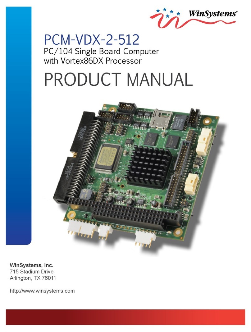
WinSystems PCM-586 User manual

Artisan Technology Group is your source for quality
new and certied-used/pre-owned equipment
• FAST SHIPPING AND
DELIVERY
• TENS OF THOUSANDS OF
IN-STOCK ITEMS
• EQUIPMENT DEMOS
• HUNDREDS OF
MANUFACTURERS
SUPPORTED
• LEASING/MONTHLY
RENTALS
• ITAR CERTIFIED
SECURE ASSET SOLUTIONS
SERVICE CENTER REPAIRS
Experienced engineers and technicians on staff
at our full-service, in-house repair center
WE BUY USED EQUIPMENT
Sell your excess, underutilized, and idle used equipment
We also offer credit for buy-backs and trade-ins
www.artisantg.com/WeBuyEquipment
REMOTE INSPECTION
Remotely inspect equipment before purchasing with
our interactive website at www.instraview.com
LOOKING FOR MORE INFORMATION?
Visit us on the web at www.artisantg.com for more
information on price quotations, drivers, technical
specications, manuals, and documentation
Contact us: (888) 88-SOURCE | sales@artisantg.com | www.artisantg.com
SM
View
Instra

OPERATIONS MANUAL
PCM-586
WinSystems Reserves the right to make changes in the circuitry
and specifications at any time without notice.
Copyright 1999 by WinSystems. All Rights Reserved.
Artisan Technology Group - Quality Instrumentation ... Guaranteed | (888) 88-SOURCE | www.artisantg.com
Revision History
P/N 403-0271-000
ECO Number Date Code Rev Level
Originated 990311 D
99-43 990419 E
99-60 990917 F
02-09 021402 G
Artisan Technology Group - Quality Instrumentation ... Guaranteed | (888) 88-SOURCE | www.artisantg.com
TABLE OF CONTENTS
Section Paragraph Page
Number Title Number
1General Information 1-1
1.1 Features 1-1
1.2 General Description 1-1
1.3 Specifications 1-2
2PCM-586 Technical Reference
2.1 Introduction 2-1
2.2 ACC Micro 2089 Processor/Chipset 2-1
2.3 Real Time Clock/Calendar 2-2
2.4 Keyboard Interface 2-2
2.5 Serial Interface 2-3
2.6 Parallel Printer Interface 2-6
2.7 Speaker/Sound Interface 2-7
2.8 PC/104 Bus Interface 2-7
2.9 Floppy Disk Interface 2-8
2.10 IDE Hard Disk Interface 2-8
2.11 Watch Dog Timer Configuration 2-9
2.12 Battery Select Control 2-10
2.13 Power/Reset Connections 2-10
2.14 Silicon Disk Configuration 2-11
2.15 Multi-I/O Connector 2-13
2.16 Status LED 2-13
2.17 Mouse Interface 2-13
2.18 CPU Clock Speed 2-14
2.19 Jumper/Connector Summary 2-15
3Award BIOS Configuration
3.1 General Information 3-1
3.2 Entering Setup 3-1
3.3 Setup Main Menu 3-1
3.4 Standard CMOS Setup 3-2
3.5 BIOS Features Setup 3-6
3.6 Chipset Features Setup 3-10
3.7 Load BIOS Defaults 3-14
3.8 Load Setup Defaults 3-14
3.9 Password Setting 3-15
3.10 IDE HDD Auto Selection 3-15
3.11 Save & Exit Setup 3-15
3.12 Exit without Saving 3-15
Artisan Technology Group - Quality Instrumentation ... Guaranteed | (888) 88-SOURCE | www.artisantg.com
4PCM-586 Silicon Disk Reference
4.1 Introduction 4-1
4.2 ROMDISK usage 4-1
4.3 Bootable RAMDISK usage 4-4
4.4 Non-Bootable RAMDISK usage 4-5
4.5 Non-Bootable FLASHDISK usage 4-6
4.6 DiskOnChip usage 4-6
5Serial Console Reference 5-1
5.1 Introduction 5-1
5.2 Wincom.exe Serial Console Client 5-1
5.3 Getting Started with the Serial Console 5-2
5.4 Serial Console Setup 5-3
5.5 Copy Files using the Serial Console 5-4
APPENDIX A Port I/O Map
APPENDIX B Interrupt Map
APPENDIX C PCM-586 Parts Placement Guide
APPENDIX D PCM-586 Parts List
APPENDIX E PCM-586 Mechanical Drawing
Artisan Technology Group - Quality Instrumentation ... Guaranteed | (888) 88-SOURCE | www.artisantg.com
1GENERAL INFORMATION
1.1 FEATURES
nHigh Integration 133MHz 5x86 Processor Board
nPC/104 Sized Module
nUp to 32 Megabytes of ruggedized SMT DRAM
nOnboard Solid State Disk support for EPROM, SRAM, or FLASH
nIndustry Standard AWARD BIOS with POST
nTwo PC Compatible Serial Ports with optional RS-422/RS-485 support
nStandard Parallel Printer Port
nWatchdog Timer with Powerfail/Reset
nOnboard 16-bit IDE Interface
nOnboard Dual Floppy Disk Controller
nStandard AT Keyboard Support
nReal-Time Clock with Battery Backup
nStatus and Hard Disk LEDs
n+5 Volt Only Operation
1.2 GENERAL DESCRIPTION
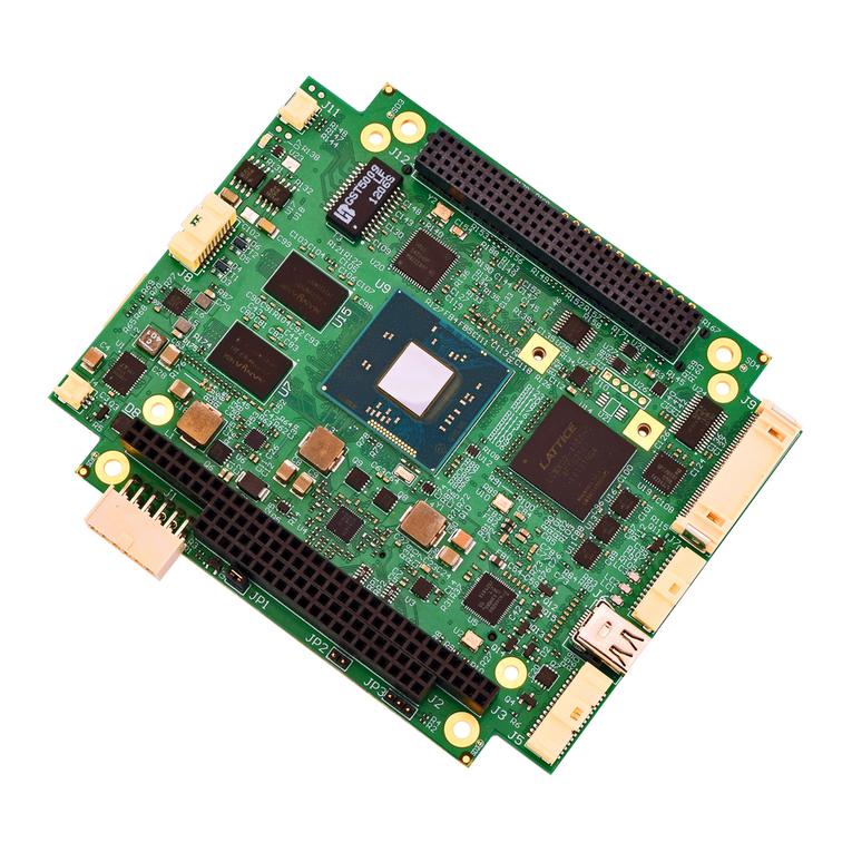
The PCM-586 is a small, high-performance, embeddable computer system on a single
PC/104formfactorboard. It features theACCMicro 2089 plustheAMD5x86 runningat
133Mhz.Itcanbepopulatedwithupto64MegabytesoffactoryinstalledSMTDRAM.Its
full PC/AT hardware, and industry standard AWARD BIOS, assure full hardware and
software compatibility with PC software and operating systems. The PCM-586 includes
on board interfaces for floppy disks, IDE fixed disks, parallel printer, and two serial
channelswith RS-232,RS-422,or RS-485capabilityoneither orboth channels. Afull 16-
bitPC/104expansionbusisprovidedforfurtherexpansiontoanentireindustryofadd-on
peripherals including high-speed VGA controllers, sound and speech modules, SCSI
controllers, Analog I/O modules, and literally hundreds of other options available from
WinSystems and a variety of vendors supporting the PC/104 standard. An onboard
Silicon Disk socket supports disks of up to 1 Megabyte in size and can utilize SRAM,
PEROM, or EPROM as the disk media. Boot capability is provided onboard, and a set of
utilitiesanddriversareincludedtomakethesilicondiskbasedsystemveryuserfriendly.
Alternately, the M-Systems’ DiskOnChip FLASH modules may be populated and disk
sizes range from 2 Megabytes to 72 Megabytes.
021402 OPERATIONS MANUAL PCM-586 Page 1-1
Artisan Technology Group - Quality Instrumentation ... Guaranteed | (888) 88-SOURCE | www.artisantg.com
1.3 Specifications
1.3.1 Electrical
Bus Interface : PC/104 8-bit or 16-bit expansion Bus
System Clock : Factory configured for 133 Mhz
Interrupts : TTL level input
VCC : +5V +/-5% at 1300mA typical at 133Mhz and 32MB DRAM
VCC1 : +12V +/-5% (Not required. PC/104 Expansion Only)
VCC2 : -12V +/-5% (Not required. PC/104 Expansion Only)
1.3.2 Memory
Addressing : 32 Megabyte addressing
BIOS ROM : 128K PEROM
Memory : Factory installed SMT DRAM in sizes from 8M to 32M
SSD Memory : One 32-pin JEDEC standard sockets support 4-MBit SRAM, 4MBit PEROM,
4-MBit EPROM, 16-MBit EPROM or the M-Systems 32-pin DOC (DiskOnChip)
module
1.3.3 Mechanical
Dimensions : 3.6 X 3.8 (without PC/104 modules or cables)
PC-Board : FR4 Epoxy Glass with 4 signal layers and 2 power planes with screened
Component legend, and plated through holes
Jumpers : 0.025” square posts on 0.10” centers
Connectors : Multi I/O : 50 pin RN type IDH-50-LP
Floppy Disk : 34 pin RN type IDH-34-LP
Fixed Disk : 40 pin RN type IDH-40-LP
PC/104 BUS : 64 pin SAMTEC type ESQ-132-12-G-D
40 pin SAMTEC type ESQ-120-12-G-D
Power/Reset Connector : 8 pin Molex 22-12-2084
Page 1-2OPERATIONS MANUAL PCM-586 021402
WinSystems - "The Embedded Systems Authority"
Artisan Technology Group - Quality Instrumentation ... Guaranteed | (888) 88-SOURCE | www.artisantg.com
Mouse : 5 pin latching type Molex 22-12-2054
Speaker : 3 pin latching type Molex 22-12-2034
1.3.4 Environmental
Operating Temperature : -40°to +70°
Non-Condensing Humidity : 5 to 95%
021402 OPERATIONS MANUAL PCM-586 Page 1-3
WinSystems - "The Embedded Systems Authority"
Artisan Technology Group - Quality Instrumentation ... Guaranteed | (888) 88-SOURCE | www.artisantg.com
2PCM-586 Technical Reference
2.1 Introduction
Thissection of the manual is intendedto providesufficient information regarding the
configuration and usage of the PCM-586 board. WinSystems maintains a Technical
SupportGrouptohelpanswerquestionsregardingconfiguration,usage,orprogramming
of the board. For answers to questions not adequately addressed in this manual, contact
Technical Support at (817) 274-7553 between 8AM and 5PM Central Time.
2.2 ACC MICRO 2089 Chipset
The PCM-586 utilizes the ACC Micro 2089 Chipset which provides a highly
integrated, high-performance backbone for full PC/AT compatibility. The 2089 contains
the logic for DRAM, CPU and Bus State control as well as the standard complement of
‘AT’ class peripherals internally, including :
8 DMA Channels compatible with PC-AT Controllers
15 Interrupt inputs compatible with master/slaved 8259 interrupt controllers
Three 8254 compatible timer/counter channels
Two 8250 compatible UARTS
EPP/ECP LPT Port
765B compatible Floppy Disk Controller
PC-AT compatible real time clock/calendar with CMOS
The functional units are 100% PC-AT compatible and are supported by the Award
BIOSandSetup. Users desiringtoaccesstheseinternal peripherals directlyshouldrefe r
to any manufacturer’s generic literature on the equivalent discrete component.
Thereareanumberofinternalregisterswithinthe2089Chipsetsectionthatareused
by the BIOS for control and configuration. Refer to the I/O Map in Appendix A for port
usage to avoid conflicts when adding external I/O devices.
021402 OPERATIONS MANUAL PCM-586 Page 2-1
Artisan Technology Group - Quality Instrumentation ... Guaranteed | (888) 88-SOURCE | www.artisantg.com
2.3 Real Time Clock Calendar
The PCM-586 contains an onboard Clock/Calendar from Dallas Semi Conductor. The
DS12885S is fully compatible with the MC146818A used in the original PC-AT
computers. This clock has a number of features including periodic and alarm interrupt
capabilities. In addition to the Time and Date keeping functions, the system
configuration is kept in CMOS RAM contained within the clock section. This RAM holds
allofthe setup informationregarding hardandfloppydisktypes,videotype,shadowing,
wait states, etc. Refer to the section on the Award BIOS Setup for complete information
on what is configured via the CMOS RAM.
It may become necessary at some time to make the CMOS RAM forget its current
configuration and to start fresh with factory defaults. This may be accomplished by
removing powerandtheboardfromthesystem.ThenremovethejumperfromJ6pins1-2
and place on pins 2-3. Then short all 3 pins of J7 together for 2 seconds. Replace the
jumper at J6 to its original position, reinstall the board, power up, and reconfigure the
setup as desired.
NOTE :J6mustalwaysbe reinstalled. The systemwillnotfunction correctly without
this jumper installed. If no battery is installed, jumper J6 pins 2-3.
2.4 Keyboard Interface
The PCM-586 contains an onboard PC-AT style keyboard controller. Connection is
made through the Multi-I/O connector at J4. An adapter cable, P/N CBL-162-1, is
available from WinSystems to make ready access to all of the devices terminated at the
Multi-I/O connector. Users desiring custom connections should refer to the Multi-I/O
connector pin definitions given later in this manual.
Page 2-2OPERATIONS MANUAL PCM-586 021402
WinSystems - "The Embedded Systems Authority"
1 2 3
o o o
J6
Master Battery Enable
Jumper J6
1 2 3
o o o
J7
Battery Backup
Jumper J7
Artisan Technology Group - Quality Instrumentation ... Guaranteed | (888) 88-SOURCE | www.artisantg.com

2.5 Serial Interface
The PCM-586 provides two RS-232 serial channels onboard, configurable as RS-422
or RS-485 with the addition of optional driver ICs. The configuration options for each of
the supported modes are shown on the following pages.
2.5.1 COM 1 - RS-232
COM1 is I/O mapped at 3F8H and utilizes a 16550-type UART contained in the 2089.
When used in RS-232 mode, COM1 is terminated via the multi-I/O connector at J4. The
configuration details and the pin definitions when used with the CBL-162-1 cable are
shown here :
021402 OPERATIONS MANUAL PCM-586 Page 2-3
WinSystems - "The Embedded Systems Authority"
3 o
2 o
1 o
J11 U11 - Installed
U10 - Not Installed
U9 - Not Installed
COM1 - DB9
PIN DEFINITIONS
3 o
2 o
1 o
J9 1 DCD
2 RX Data
3 TX Data
4 DTR
5 GND
6 DSR
7 RTS
8 CTS
9 RI
3 o
2 o
1 o
J10
3 o
2 o
1 o
J11
3 o
2 o
1 o
J9
3 o
2 o
1 o
J8
Artisan Technology Group - Quality Instrumentation ... Guaranteed | (888) 88-SOURCE | www.artisantg.com
2.5.2 COM 2 - RS-232
COM2isI/Omappedat2F8Handutilizesa16550-typeUARTcontainedintheSuper-
I/O chip. When used in RS-232 mode COM2 is terminated via the multi-I/O connector at
J4.Theconfiguration detailsand thepindefinitions whenused with theCBL-162-1 cable
are shown here :
2.5.3 RS-422 Mode Configuration
RS-422 signal levels are supported on either, or both serial channels with the
installation of the optional “Chip Kit” WinSystems’ part number CK-75176-2. This kit
provides the driver ICs necessary for a signal channel of RS-422. If two channels of RS-
422 are required then two kits will be needed. RS-422 is a 4-wire point-to-point full-
duplex interface allowing much longer cable runs than are possible with RS-232. The
differentialtransmitterand receivertwisted-pairsoffer ahighdegree ofnoiseimmunity.
RS-422 usually requires that the lines be terminated at both ends. The following
illustrations show the correct jumpering, driver IC installation, and I/O connector pin
definitions for each of the channels when used in RS-422 mode.
2.5.4 COM 1 - RS-422
RS-422 NOTE :When used in RS-422 mode, the transmitter must be enabled via
software by setting the RTS bit in the Modem Control Register (Bit 1).
Page 2-4OPERATIONS MANUAL PCM-586 021402
WinSystems - "The Embedded Systems Authority"
3 o
2 o
1 o
J8 U8 - Installed
U7 - Not Installed
U6 - Not Installed
COM2 - DB9
PIN DEFINITIONS
3 o
2 o
1 o
J10 1 DCD
2 RX Data
3 TX Data
4 DTR
5 GND
6 DSR
7 RTS
8 CTS
9 RI
COM1 - DB9
PIN DEFINITIONS
U11 - Not Installed
U10 - Installed
U9 - Installed
3 o
2 o
1 o
J9
3 o
2 o
1 o
J11 1 N/A
2 TX+
3 TX-
4 N/A
5 GND
6 RX+
7 RX-
8 N/A
9 N/A
Artisan Technology Group - Quality Instrumentation ... Guaranteed | (888) 88-SOURCE | www.artisantg.com
2.5.5 COM 2 - RS-422
RS-422NOTE:WhenusedinRS-422mode,thetransmittermust
be enabled via software by setting the RTS bit in the Modem Control Register (Bit 1).
2.5.6 RS-485 Mode Configuration
The RS-485 muti-drop interface is supported on both serial channels with the
installationoftheoptional“ChipKit”WinSystems’partnumberCK-75176-2.Asinglekit
issufficienttoconfigurebothchannelsforRS-485.RS-485isa2-wiremulti-dropinterface
whereonlyonestationatatimetalks(transmits)whileallotherslisten(receive).RS-485
usuallyrequires thetwistedline-pairbe terminatedateach endofthe run.The following
illustrationsshowthecorrectjumpering,driverICinstallation,andI/Oconnectorpin-out
for each of the channels when used in RS-485 mode.
2.5.7 COM 1 - RS-485
RS-485 NOTE :Because RS-485 uses a single twisted-pair, all transmitters are
connectedinparallel.Onlyonestationmaytransmit,orhaveitstransmitterenabledata
time.Thetransmitterenable/disableiscontrolledbyBit1intheModemControlRegister
(RTS). When set, the transmitter is enabled, when cleared (the normal state), the
transmitterisdisabledandthereceiverisenabled.Notethatitisnecessarytoallowsome
minimal settling time after enabling the transmitter before transmitting the first
character. Likewise, following a transmission, it is necessary to be sure that all
characters have been completely shifted out of the UART (Check Bit 6 in the Line Status
Register) before disabling the transmitter to avoid chopping off the last character sent.
021402 OPERATIONS MANUAL PCM-586 Page 2-5
WinSystems - "The Embedded Systems Authority"
COM1 - DB9
PIN DEFINITIONS
U11 - Not Installed
U10 - Not Installed
U9 - Installed
3 o
2 o
1 o
J9
3 o
2 o
1 o
J11
Normal RS-485 operation is
achieved by jumpering J9 pins
1-2. For RS-485 with
Echo-back jumper pins 2-3
1 N/A
2 TX+/RX+
3 TX-/RX-
4 N/A
5 GND
6 N/C
7 N/C
8 N/A
9 N/A
COM2 - DB9
PIN DEFINITIONS
U8 - Not Installed
U7 - Installed
U6 - Installed
3 o
2 o
1 o
3 o
2 o
1 o
1 N/A
2 TX+
3 TX-
4 N/A
5 GND
6 RX+
7 RX-
8 N/A
9 N/A
J10 J8
Artisan Technology Group - Quality Instrumentation ... Guaranteed | (888) 88-SOURCE | www.artisantg.com
2.5.8 COM 2 - RS-485
RS-485 NOTE :Because RS-485 uses a single twisted-pair, all transmitters are
connectedinparallel.Onlyonestationmaytransmit,orhaveitstransmitterenabledata
time.Thetransmitterenable/disableiscontrolledbyBit1intheModemControlRegister
(RTS). When set, the transmitter is enabled, when cleared (the normal state), the
transmitterisdisabledandthereceiverisenabled.Notethatitisnecessarytoallowsome
minimal settling time after enabling the transmitter before transmitting the first
character. Likewise, following a transmission, it is necessary to be sure that all
characters have been completely shifted out of the UART (Check Bit 6 in the Line Status
Register) before disabling the transmitter to avoid chopping off the last character sent.
2.6 Parallel Printer Interface
The PCM-586 supports a standard parallel printer port. An optional configuration is
availablewith aparallel portcapable of enhancedEPP and ECP operations. The parallel
port is I/O mapped at 278H and is terminated at the Multi-I/O connector J4. The pin
definitionsfor the parallelport connectorDB-25, whenused withthe CBL-162-1,cableis
shown below :
Page 2-6OPERATIONS MANUAL PCM-586 021402
WinSystems - "The Embedded Systems Authority"
COM1 - DB9
PIN DEFINITIONS
U8 - Not Installed
U7 - Not Installed
U6 - Installed
3 o
2 o
1 o
J8
3 o
2 o
1 o
J10
Normal RS-485 operation is
achieved by jumpering J8 pins
1-2. For RS-485 with Echo-back
jumper pins 2-3
1 N/A
2 TX+/RX+
3 TX-/RX-
4 N/A
5 GND
6 N/C
7 N/C
8 N/A
9 N/A
1 o o 14
2 o o 15
3 o o 16
4 o o 17
5 o o 18
6 o o 19
7 o o 20
8 o o 21
9 o o 22
10 o o 23
11 o o 24
12 o o 25
13 o
STROBE
PD0
PD1
PD2
PD3
PD4
PD5
PD6
PD7
ACK
BUSY
PE
SLCT
AUTOFD
ERROR
INIT
SLIN
GND
GND
GND
GND
GND
GND
GND
GND
Artisan Technology Group - Quality Instrumentation ... Guaranteed | (888) 88-SOURCE | www.artisantg.com

2.7 Speaker/Sound Interface
Audio power for the PCM-586 can be accessed thru the connector at J1. Pin 1 drives a
+5 volt digital line suitable for Piezo-type transducers. Pin definitions for J1 are given
below.
2.8 PC/104 Bus Interface
ThePCM-586supportsI/Oexpansion throughthestandardPC/104connectorsat J16
and J17. The PCM-586 supports both 8-bit and 16-bit PC/104 modules. The PC/104
connector pin definitions are provided here for reference.
021402 OPERATIONS MANUAL PCM-586 Page 2-7
WinSystems - "The Embedded Systems Authority"
B1 o o A1
B2 o o A2
B3 o o A3
B4 o o A4
B5 o o A5
B6 o o A6
B7 o o A7
B8 o o A8
B9 o o A9
B10 o o A10
B11 o o A11
B12 o o A12
B13 o o A13
B14 o o A14
B15 o o A15
B16 o o A16
B17 o o A17
B18 o o A18
B19 o o A19
B20 o o A20
B21 o o A21
B22 o o A22
B23 o o A23
B24 o o A24
B25 o o A25
B26 o o A26
B27 o o A27
B28 o o A28
B29 o o A29
B30 o o A30
B31 o o A31
B32 o o A32
GND
RESET
+5V
IRQ9
-5V
DRQ2
-12V
0WS
+12V
GND
MEMW
MEMR
IOW
IOR
DACK3
DRQ3
DACK1
DRQ1
REFRESH
SYSCLK
IRQ7
IRQ6
IRQ5
IRQ4
IRQ3
DACK2
TC
BALE
+5V
OSC
GND
GND
IOCHK
BD7
BD6
BD5
BD4
BD3
BD2
BD1
BD0
IOCHRDY
AEN
SA19
SA18
SA17
SA16
SA15
SA14
SA13
SA12
SA11
SA10
SA9
SA8
SA7
SA6
SA5
SA4
SA3
SA2
SA1
SA0
GND
C0 o o D0
C1 o o D1
C2 o o D2
C3 o o D3
C4 o o D4
C5 o o D5
C6 o o D6
C7 o o D7
C8 o o D8
C9 o o D9
C10 o o D10
C11 o o D11
C12 o o D12
C13 o o D13
C14 o o D14
C15 o o D15
C16 o o D16
C17 o o D17
C18 o o D18
C19 o o D19
GND
SBHE
LA23
LA22
LA21
LA20
LA19
LA18
LA17
MEMR
MEMW
SD8
SD9
SD10
SD11
SD12
SD13
SD14
SD15
KEY
GND
MEMCS16
IOCS16
IRQ10
IRQ11
IRQ12
IRQ15
IRQ14
DACK0
DRQ0
DACK5
DRQ5
DACK6
DRQ6
DACK7
DRQ7
VCC
MASTER
GND
GND
J16 J17
1 o
2 o
3 o
J1
+5
GND
Audio
Artisan Technology Group - Quality Instrumentation ... Guaranteed | (888) 88-SOURCE | www.artisantg.com
2.9 Floppy Disk Interface
ThePCM-586supportsupto2standard3½”or5¼”PCcompatiblefloppydiskdrives.
The drives are connected via the I/O connector at J3. Note that the interconnect cable to
the drives is a standard floppy I/O cable used on desktop PCs. The cable must have the
twisted section prior to the drive A position. The pin definitions for the J3 connector are
shown here for reference.
2.10 IDE Hard Disk Interface
The PCM-586 supports standard IDE fixed disks through the I/O connector at J5. A
redactivityLEDispresentatD1.ThepindefinitionsfortheJ5connectorareshownhere.
Page 2-8OPERATIONS MANUAL PCM-586 021402
WinSystems - "The Embedded Systems Authority"
1 o o 2
3 o o 4
5 o o 6
7 o o 8
9 o o 10
11 o o 12
13 o o 14
15 o o 16
17 o o 18
19 o o 20
21 o o 22
23 o o 24
25 o o 26
27 o o 28
29 o o 30
31 o o 32
33 o o 34
GND
GND
GND
GND
GND
GND
GND
GND
GND
GND
GND
GND
GND
GND
GND
GND
GND
RPM/LC
N/C
N/C
INDEX
MTR0
DRV1
DRV0
MTR1
DIR
STEP
WDATA
WGATE
TRK0
WPRT
RDATA
HDSEL
DSKCHG
J3
1 o o 2
3 o o 4
5 o o 6
7 o o 8
9 o o 10
11 o o 12
13 o o 14
15 o o 16
17 o o 18
19 o o 20
21 o o 22
23 o o 24
25 o o 26
27 o o 28
29 o o 30
31 o o 32
33 o o 34
35 o o 36
37 o o 38
39 o o 40
RESET
D7
D6
D5
D4
D3
D2
D1
D0
GND
N/C
IOW
IOR
N/C
N/C
IRQ14
A1
A0
HDCS0
N/C
GND
D8
D9
D10
D11
D12
D13
D14
D15
N/C
GND
GND
GND
N/C
GND
IOCS16
N/C
A2
HDCS1
GND
J5
Artisan Technology Group - Quality Instrumentation ... Guaranteed | (888) 88-SOURCE | www.artisantg.com
2.11 Watchdog Timer Configuration
The PCM-586 board features a power-on voltage detect and a power-down/power
brownout reset circuit to protect memory and I/O from faulty CPU operation during
periodsofillegalvoltagelevels.This supervisory circuitryalsofeaturesawatchdog timer
whichcanbeusedtoguardagainstsoftware lockups.Aninternalself-timerwithaperiod
of 1.5 seconds will, when enabled, reset the CPU if the watchdog has not been serviced
(petted) within the allotted time. There are three watchdog operational modes available
onthePCM-586.WithnojumperinstalledonJ2,thewatchdogistotallydisabledandcan
never reset the CPU. When J2 is jumpered pins 2-3, the watchdog circuit is permanently
enabled and timing begins immediately with power-on. This mode is NOT compatible
with the Award BIOS or with MS-DOS, but is available for directly embedded code that
takestheplaceoftheBIOS.Thewatchdogmustbeaccessedatleastevery1.5secondsora
resetwilloccur.PettinginthismodeisaccomplishedbywritingtoI/Oport1EEHwithan
alternating 1 and 0 value.
The alternate mode of operation is via software enable/disable control. This mode is
set by jumpering J2 pins 1-2. In this mode the watchdog timer powers-up disabled and
mustbeenabledinsoftwarebeforetimingwillbegin.Enablingisaccomplishedbywriting
a 1 to I/O port 1EEH. Writing a 0 to I/O port 1EEH will disable the watchdog. After
enabling, the watchdog must be serviced at least every 1.5 seconds or a reset will occur.
The petting is accomplished by simply writing any value to I/O port 1EFH. This mode of
operation can be used with the BIOS and DOS provided that the watchdog is disabled
before making any extensive BIOS or DOS calls, especially video or disk I/O calls, which
in some cases could exceed the 1.5 seconds allowed. The drawback to this mode is that a
lockup during the time the watchdog is disabled will not allow for auto-recovery but will
require an external source for a reset.
021402 OPERATIONS MANUAL PCM-586 Page 2-9
WinSystems - "The Embedded Systems Authority"
1 o
2 o
3 o
J2
Watchdog timer
configuration jumper J2
Battery enable jumper J6
J6
1 2 3
o o o
Artisan Technology Group - Quality Instrumentation ... Guaranteed | (888) 88-SOURCE | www.artisantg.com

2.12 Battery Selection Control
The PCM-586 has an onboard lithium battery used to sustain the Clock/Calendar
CMOS setup information, and Solid State Disk information when SRAMs are used. A
masterbatteryenablejumperisprovidedatJ6.WithJ6unjumperedthebatteryistotally
disconnected and no battery voltage is supplied to any circuitry on the board. The Solid
State Disk socket may be jumpered for battery backup when using SRAMs if desired.
Refer to the Silicon Disk Configuration section of this manual for details. It may become
necessaryordesirableatsometimetoerasetheCMOSsetupinformationduetoincorrect
or undesirable settings which are causing an inability to execute the setup utility or
improper operation. To reset the CMOS memory to factory defaults, remove the jumper
from J6 1-2 and place on J6 2-3. Then short all 3 pins of J7 together for 2 seconds, then
restore the jumper to J6 pins 1-2. This should result in the BIOS restoring defaults and
prompting for setup during the next boot. Refer to section 3, “AWARD BIOS
Configuration”, for setup options and details.
2.13 Power/Reset Connections
Power is applied to the PCM-586 via the connector at J18. The pin definitions for J18
are given below. An optional push-button-reset (Normally Open) may also be routed into
J18 if desired.
Page 2-10 OPERATIONS MANUAL PCM-586 021402
WinSystems - "The Embedded Systems Authority"
o o o o o o o o
8 7 6 5 4 3 2 1
J18
8 o
7 o
6 o
5 o
4 o
3 o
2 o
1 o
PBRESET*
GND
GND
GND
+5V
+5V
+12V
-12V
J18
Artisan Technology Group - Quality Instrumentation ... Guaranteed | (888) 88-SOURCE | www.artisantg.com

2.14 Silicon Disk Configuration
The PCM-586 supports the use of EPROM, PEROM (Flash), SRAM, and the M-
Systems DiskOnChip (DOC) devices to be used as a Solid State Disk drive. Section 4 of
this manual provides the necessary information for the generation and usage of the
Silicon drive. This section documents the required hardware configurations for the
various types of devices. The 32-pin JEDEC memory socket at U3 is used to contain the
RAM, ROM, Flash, or DOC device used for the disk. The Silicon disk array is memory
mappedintoa32KbyteholeatsegmentE800HandhasanI/Ocontrolregisterat1ECH.
2.14.1 Silicon Disk Mode
There are two basic modes of Silicon Disk operation available on the PCM-586. The
first uses the onboard BIOS extension and supports the use of a 512K or 1M EPROM,
512K SRAM, or 512K ATMEL Flash device. The second mode uses the M-Systems
021402 OPERATIONS MANUAL PCM-586 Page 2-11
WinSystems - "The Embedded Systems Authority"
1 2 3
o o o
J7
10 o o 9
8 o o 7
6 o o 5
4 o o 3
2 o o 1
J12
Silicon Disk Configuration
Jumpers J7 and J12
1 o o 2
J15
1 o o 2
J15
EPROM, SRAM, PEROM USAGE DOC USAGE
Artisan Technology Group - Quality Instrumentation ... Guaranteed | (888) 88-SOURCE | www.artisantg.com

DiskOnChip device. The mode is controlled via pins 1-2 on jumper block at J15 as shown
here :
Page 2-12 OPERATIONS MANUAL PCM-586 021402
WinSystems - "The Embedded Systems Authority"
Artisan Technology Group - Quality Instrumentation ... Guaranteed | (888) 88-SOURCE | www.artisantg.com
Table of contents
Other WinSystems Motherboard manuals

WinSystems
WinSystems SYS-405 User manual

WinSystems
WinSystems SBC35-427 Owner's manual

WinSystems
WinSystems CX 3-26 User manual

WinSystems
WinSystems ITX-N-3815-1-0 User manual

WinSystems
WinSystems PCM-C418 User manual

WinSystems
WinSystems EBC-C384-D User manual

WinSystems
WinSystems EPX-C380 User manual

WinSystems
WinSystems PPM-C407 User manual

WinSystems
WinSystems ENC-EPX-G-1000 User manual

WinSystems
WinSystems SAT-520PLUS User manual