WIRAL wiral lite User manual

USER MANUAL
BENUTZERHANDBUCH
MANUEL UTILISATEUR
MANUAL DE USUARIO
MANUALE UTENTE
MANUAL DO USUÁRIO
BRUKSANVISNING
ユーザーマニュアル
用户手册
РУКОВОДСТВО ПОЛЬЗОВАТЕЛЯ

TO DOWNLOAD THIS USER MANUAL IN A DIFFERENT LANGUAGE,
VISIT WIRALCAM.COM/SUPPORT.
WENN SIE DIESES BENUTZERHANDBUCH IN EINER ANDEREN SPRACHE
HERUNTERLADEN MÖCHTEN, BESUCHEN SIE WIRALCAM.COM/SUPPORT.
POUR TÉLÉCHARGER CE MANUEL DE L’UTILISATEUR DANS UNE AUTRE
LANGUE, RENDEZ-VOUS SUR WIRALCAM.COM/SUPPORT.
PARA DESCARGAR ESTE MANUAL DE USUARIO EN OTRO IDIOMA,
VISITE WIRALCAM.COM/SUPPORT.
PER SCARICARE QUESTO MANUALE UTENTE IN UN’ALTRA LINGUA,
VISITA WIRALCAM.COM/SUPPORT.
PARA BAIXAR ESTE MANUAL DO USUÁRIO EM OUTRO IDIOMA,
ACESSE WIRALCAM.COM/SUPPORT.
FOR Å LASTE NED DENNE BRUKERHÅNDBOKEN PÅ ET ANNET SPRÅK,
BESØK WIRALCAM.COM/SUPPORT.
FÖR ATT LADDA NER DEN HÄR BRUKSANVISNINGEN PÅ ETT ANNAT SPRÅK,
BESÖK WIRALCAM.COM/SUPPORT.
このユーザーマニュアルの他言語版をダウンロードするに
は、 WIRALCAM.COM/SUPPORT にアクセスしてください。
若要下載其他語言版本的使用說明書,請前往:
WIRALCAM.COM/SUPPORT。
如需下载本用户手册的其他语言版本,请访问
WIRALCAM.COM/SUPPORT。
Чтобы загрузить это руководство пользователя на другом языке,
посетите страницу WIRALCAM.COM/SUPPORT.

BOOM! Thanks for purchasing Wiral LITE
and welcome to our family!
(Please take your brand new Wiral LITE
slowly out of the box while reading this
imagining Morgan Freemans voice, for a
dramatic eect)
There are those of us that like to explore
the unexplored, go out there with a fresh
and open mind. Those of us that go out
there, with a sense of… curiosity. We
believe that this is why you got yourself
a Wiral LITE, and we believe that this
is why you will go out there and create
videos never seen before. Because we
believe you are the future of content
creators and that the best tools for
content creations should be available to
you. Go out, be curious, be creative, be
proud and explore the world with your
Wiral LIFE.
WELCOME TO OUR FAMILY!
www.wiralcam.com/how-to-use
Go to the address or scan the
QR code below to watch a
video tutorial on how to use
Wiral LITE safely:

1. Read the complete manual before using
the product.
2. The user holding the remote control
is legally the operator of the unit. The
operator is responsible for safe usage
and consequences of unsafe usage of the
unit and the line. Wiral Technologies AS is
not responsible for any injury, damage of
property or harm caused by usage of Wiral
LITE and accessories.
3. The appliance is not intended for use by
persons (including children) with reduced
physical, sensory or mental capabilities,
or lack of experience and knowledge,
unless they have been given supervision
or instruction concerning the use of the
appliance by a person responsible for their
safety.
4. Do not breach the bounds of privacy. Ask
for permission before using Wiral LITE on
private property.
5. Do not use the Wiral LITE while under the
influence of drugs or alcohol.
DISCLAIMERS

To avoid injuries and damages to property:
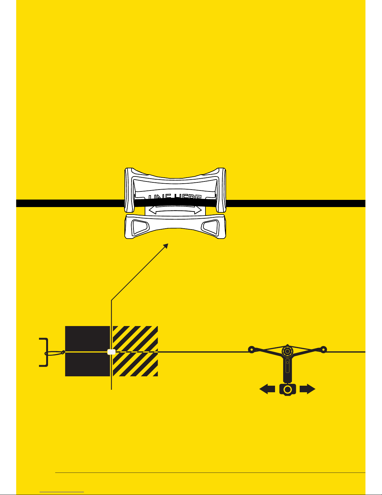
1. Keep control of the immediate
environment and keep Wiral LITE in line of
sight at all times when operating the unit.
Wiral LITE requires a certain line length for
braking and stopping (See page 11). Lack of
attention can result in crashing it into the
end anchor points or other obstacles.
2. To keep the Quick Reel™, tightening
strap, or rope from breaking, and prevent
the resulting injuries/damages to property,
follow these instructions:
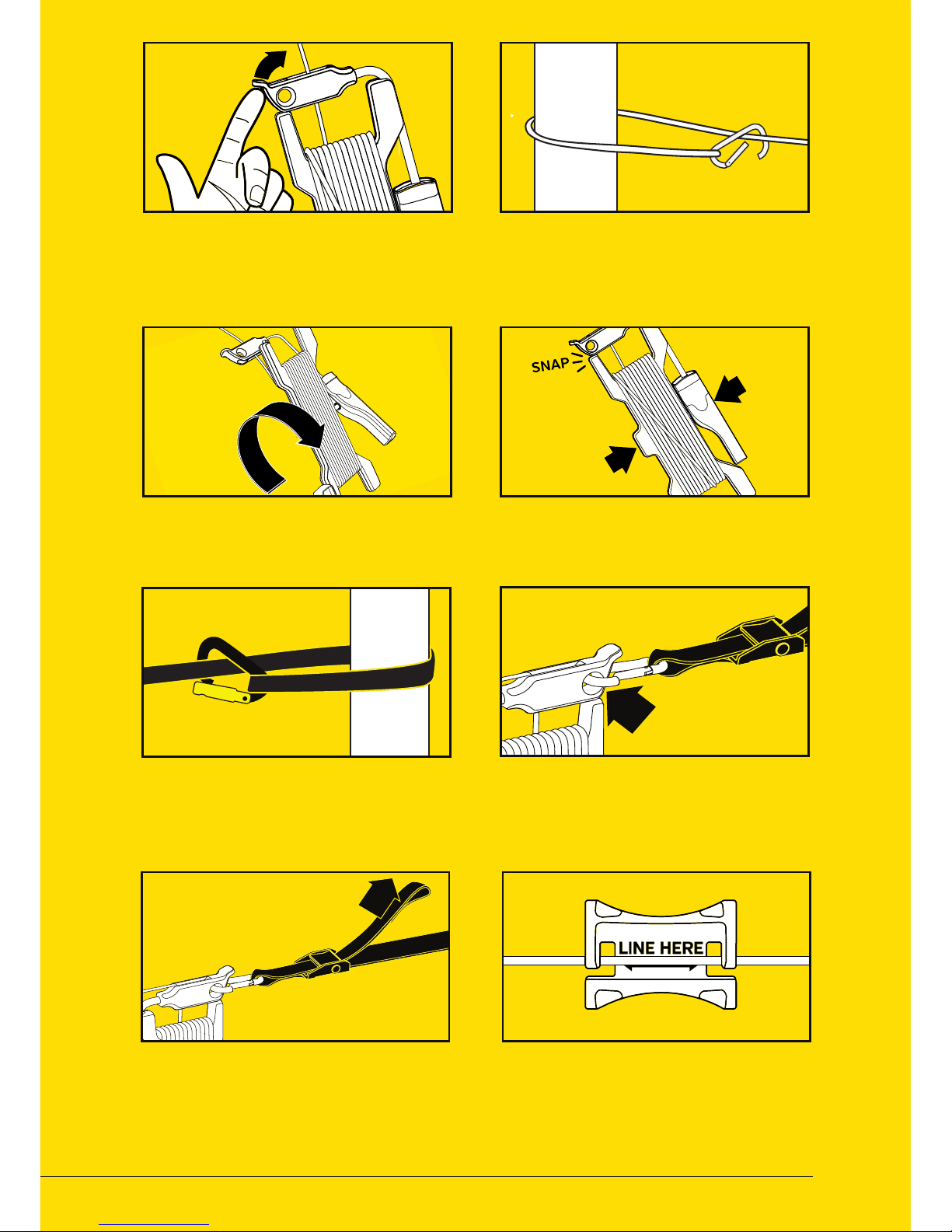
• Always make sure the Quick Reel™ is
securely locked when tightening the
rope.
• Do not set up the line in locations where
it might interfere with, or block trac or
anything that might crash into the line
(e.g. trails, roads).
• Do not set up the line near heat sources,
sharp objects or in another way that
lead to the line being cut (e.g. open
flame, concert lights, sharp rocks)
• Do not set up the line on weak or
unstable anchors or anchor points that
do not have a fixed distance
• Never overtighten the Quick Reel™. Do
not tighten above 390N (40kg/90lbs).
(Replace strap if safety seam is
breached).
• Do not pull or apply pressure on a line
that is fully tightened.
• Release the control wheel and stop the
Wiral LITE immediately if it derails or if
an obstacle keeps it from moving freely.
• Never exceed maximum payload of
1.5kg (3.3 lbs)
• Do not leave the line mounted
unsupervised.
3. Warning! Misuse of battery could lead to
risk of fire and burns.
4. Always make sure that the Wiral LITE and
the remote control is powered on and the
line is tightened before mounting Wiral LITE
on the line, and do not loosen or tighten the
line while the unit is mounted.
5. Do not touch the motor when the product
is in use or immediately aer use.
6. Do not expose Wiral LITE to water. It is
not waterproof and cannot be used under
water. [do not use in snowstorm, sandstorm,
or other extreme weather]
7. Do not use in temperatures below -15°C
and above 50°C
8. Do not use Wiral LITE in wind conditions
exceeding 10 m/s (22 mph), or in other
severe weather conditions.
9. Do not use in areas with high levels of
interference (e.g. radio transmission towers).
10. Store the kit in room temperature, in a
dry environment and shielded from sunlight.
Maximum line strength may decrease over
time.
11. Always keep Wiral LITE, all accessories
and packaging out of reach of children and
infants.
12. Never use 3rd party accessories including
3rd party rope as a replacement for the
original parts. Only use genuine certified
Wiral replacement parts.
CAUTION

6
WHAT’S IN THE BOX
END STOP CLIP
TIGHTENING STRAP
QUICK REEL
WIRAL LITE
ROPE
REMOTE CONTROL

7
PULL
QUICK SETUP
END STOP CLIP
TIGHTENING STRAP
QUICK REEL
WIRAL LITE
ROPE
REMOTE CONTROL
1
2
3
SET UP THE
ROPE SYSTEM
READ MORE ON PAGE 8-9
READ MORE ON PAGE 10-11
READ MORE ON PAGE 14-19
MOUNT
WIRAL LITE
CONTROL
WIRAL LITE
Wiral LITE can easily be set up in less than 3 minutes. To learn how to do it,
follow the instructions on the next pages.

8
ROPE GUIDE
B
CARABINER ATTACHMENT POINT
A
ROPE
D
HANDLE
F
ROTATY KNOB
G
ROPE CARABINER
E
ROPE REEL
C
LARGE STRAP CARABINER
H
TIGHTENING STRAP
I
TIGHTENING BUCKLE
K
SMALL STRAP CARABINER
J
QUICK REEL™
The Wiral LITE kit comes with the Quick Reel™ that
makes it possible to set up the line in just a few
minutes. The Quick Reel™ consists of a reel
for handling the rope and a tightening
strap for connecting and
tightening it.
1

9
01 UNLOCK QUICK REEL™
03 UNWIND ROPE
05 FASTEN STRAP
07 TIGHTEN STRAP 08 MOUNT END STOPS
Press rope guide to unlock Quick
Reel™ and unwind the rope.
Pull out the rope and let the reel rotate
freely to unwind the rope.
Place the tightening strap around the
second attachment point, and
attach the large strap carabiner.
Tighten the system by pulling the
end of the strap with a maximum
force of 40 kg / 390 Nm.
Mount the physical end stops close to the
attachment point on each side. See next
page.
Place the rope around the first
attachment point, and attach the
carabiner to the rope
Lock the Quick Reel™ when you are close
to the second attachment point.
Connect the small strap carabiner to
the Quick Reel™ rope guide.
02 ATTACH CARABINER
04 LOCK QUICK REEL™
06 ATTACH STRAP
PULL
PULL
PUSH
PUSH

10
MOUNTING OF END STOP CLIPS
The kit includes two end stop clips. The clips should be mounted
on to the rope in a recommended distance from each attachment
point. The distance can be found in the table on the next page.
This will help avoiding Wiral LITE crashing into the attachement
points. When the end stop is mounted, it will either derail or stop
the unit before it is reaching the end of the line.
BRAKING
DISTANCE
END
STOP
CLIP
SAFETY
ZONE
BRAKING
DISTANCE
END
STOP
CLIP
SAFETY
ZONE

11
BRAKING
DISTANCE
END
STOP
CLIP
SAFETY
ZONE BRAKING
DISTANCE
END
STOP
CLIP
SAFETY
ZONE
BRAKING DISTANCE AND SAFETY ZONE
SAFETY ZONE
INCLINE
BRAKING DISTANCE
The end stop clip should be mounted with a safety zone between itself and the end
of the line to avoid Wiral LITE from crashing into the attachment point. The length of
the zone will vary with the weight of the camera used.
The maximum incline of Wiral LITE varies with the weight of the camera
attached to it. See the table below to check how steep your setup can move.
Maximum braking distance of Wiral LITE will be dierent based on the weight of
the camera that is used.
0 - 500 g
(0 - 1.1 lb)
500 - 1000 g
(1.1 - 2.2 lb)
1000 - 1500 g
(2.2 - 3.3 lb)
Horizontal 4 m / 13 5.5 m / 18 7 m / 23
Max. Incline 2 m / 6.5 2 m / 6.5 2 m / 6.5
Max. Decline 5 m / 16.5 7 m / 23 9 m / 29.5
*The values are estimates, and may vary with environmental conditions.
0 - 500 g
(0 - 1.1 lb)
500 - 1000 g
(1.1 - 2.2 lb)
1000 - 1500 g
(2.2 - 3.3 lb)
Horizontal 3 m / 10 4 m / 13 5 m / 16.5
Max. Incline 1.5 m / 5 1.5 m / 5 1.5 m / 5
Max. Decline 5 m / 16.5 7 m / 23 9 m / 29.5
0 - 500 g
(0 - 1.1 lb)
500 - 1000 g
(1.1 - 2.2 lb)
1000 - 1500 g
(2.2 - 3.3 lb)
Max. Incline 30° 25° 10°
*The values are estimates, and may vary with environmental conditions.

12
MAIN UNIT
LOCK PIN
A
ON / OFF BUTTON
C
BATTERY COMPARTMENT
D
LOCK PIN PULLER
B
BATTERY
H
PULLEY
I
CAMERA MOUNT
G
ARM
F
BATTERY CONNECTOR
E
Aer mounting the line, it is time to prepare the
main unit, including the batteries
and the camera that is going
to be attached.
2

13
01 CHARGE BATTERY
04 MOUNT CAMERA
02 INSERT BATTERY
07 SECURE THE UNIT 08 CONNECT TO REMOTE
Charge battery using the charger
included in the kit. Read more
on page 18 - 19.
Mount your camera on to the
universal camera screw.
Insert battery and connect it to the
power plug. The unit automatically
turns on.
Secure the unit by opening the lock pin,
let the line pop into place. Make sure
that the line is placed in the drive wheel
groove.
If the remote is switched on, it will
connect automatically. If not connected,
all LEDs will be blinking. To lock the remote
to just one unit, read more on page 22.
Mount the ball joint to be able to point
your camera in any angle.
Mount the unit on the line by placing the
line under the two pulleys and over the
drive wheel.
Make sure the unit is powered on, use
the button to toggle power on or o.
03 MOUNT BALL JOINT
06 MOUNT ON LINE
05 POWER ON

14
CONTROL WHEEL
MODE BUTTON
SET END STOP 1
SET END STOP 2
PLAY / PAUSE
MODE INDICATOR
END STOP INDICATORS
BATTERY COMPARTMENT
SPEED & BATTERY
INDICATOR
A
B
C
D
E
F
G
H
I
REMOTE CONTROL
Normal Mode: Control the speed from 0 to 0.7 m/s (0 - 1.6 mph)
directly by turning the speed wheel. (Page 16)
Wiral LITE can be operated by using the remote control included in the
kit. The remote control is controlling speed and acceleration, setting
digital end stops, and giving feedback through six LED lights.
Wiral Lite has three dierent control modes:
Sport Mode: Control the speed from 0 to 9 m/s (0 - 20 mph)
directly by turning the speed wheel. (Page 17)
Time lapse Mode: The unit moves slowly back and forth
between the digital end stops in speeds
up to 0.01 m/s (0.02 mph). (Page 18)
1
2
3
3

15
01 POWER ON
03 SET DIGITAL END STOP
02 CONTROL MOVEMENT
04 SET SECOND END STOP
06 END STOPS NOT SET
05 REMOVE END STOP
Press the Mode Button to turn on the
remote control. The Mode LED will
turn on. Hold the same button for 2
seconds to turn o.
Set digital end stops by moving the
main unit to the point you want it
to automatically stop and press the
end stop button. The yellow end stop
button will set a digital end stop in
the direction of the arm marked with a
yellow stripe.
Rotate the Speed Wheel to move
the main unit. Rotating towards the
yellow arrow, will move the main unit
in direction of the arm marked with a
yellow stipe.
Move the main unit to the second point
you want it to automatically stop and
press the opposite end stop button.
The main unit will now only move in
between these points. Be aware that
the end stops might dri. They should
be reset aer emergency stops. Use end
stop clips for extra safety.
Setting digital end stops is highly
recommended. In time lapse mode the
indicators will blink if the end stops
are not set.
Remove end stop by holding the end
stop button for 2 seconds. To replace
an end stop, just click the end stop
button when you want to place it.

16
YELLOW
DIRECTION
MARKS
ON ARM
SPEED WHEEL
MODE INDICATOR
NORMAL MODE
CHANGE SPEED MODE
Control the speed from 0 to 1.4 m/s
(0 - 4.5 fps) directly by turning the speed
wheel.
When in Normal Mode, the mode
indicator will fade slowly in and out.
Moving the speed wheel clockwise
(towards the yellow arrow) will make the
main unit move towards the side with
yellow direction mark.
When the speed wheel is released, the
unit will stop.
01 CHANGE MODE 02 MODE INDICATION
The remote is automatically set to
normal mode when turned on. Change
modes by pressing the mode button.
Normal Mode: Mode indicator LED is
blinking slowly.
Sport Mode: Mode indicator LED is
blinking fast.
Time Lapse Mode: Mode indicator LED
is continously lit.
2
1
3
4

17
YELLOW
DIRECTION
MARKS
ON ARM
SPEED WHEEL
MODE INDICATOR
SPORT MODE
Control the speed from 0 to 9.5 m/s
(0 - 31 fps) directly by turning the speed
wheel.
When in Sport Mode, the mode
indicator will fade quickly in and out.
Moving the speed wheel clockwise
(towards the yellow arrow) will make the
unit move towards the side with yellow
direction marks.
When the speed wheel is released, the
unit will stop.
2
1
3
4

18
DIRECTION
MARKS
ON ARM
SPEED WHEEL
MOVE / PAUSE
BUTTON
Control the acceleration by turning the
speed wheel. Moving the speed wheel
clockwise (towards the yellow arrow) will
accelerate the unit towards the side with
yellow direction marks.
When in Time Lapse Mode, the mode
indicator is continously lit.
When releasing the wheel, the unit will
continue in the same speed.
2
1
3
4
TIME LAPSE MODE
Pause the unit by pressing the move /
pause button on the remote. The speed
can be adjusted both in paused and
moving state.
To reset the speed to zero, click the
play/pause button twice.
The unit restarts when the play/pause
button is pressed for the second time.
5
6
WARNING!
Time lapse mode should only be used with horizontal line. Incline on
the line can lead to overheating.

19
CHECK BATTERY STATUS
LED STATES
NORMAL MODE
SPORT MODE
END STOP 1 AND 2 SET
TIME LAPSE MODE
END STOP NOT SET
NOT CONNECTED, ERROR OR OVERHEAT
TIME LAPSE SPEED LEVEL 1
TIME LAPSE SPEED LEVEL 4
TIME LAPSE SPEED LEVEL 2
TIME LAPSE SPEED LEVEL 5
TIME LAPSE SPEED LEVEL 3
TIME LAPSE SPEED LEVEL 6
Mode indicator is fading slowly in and out.
Mode indicator is fading quickly in and out.
When end stop indicators are lit, digital end stops are set
Mode indicator is continously lit.
If digital end stops are not set in Time Lapse Mode, LEDs will blink.
If the remote is not connected to the main unit, having an
unexpected error or overheating all six LEDs will blink at the
same time.
3.3 m / 10.7 per hour in Time Lapse Mode.
12.9 m / 42.2 per hour in Time Lapse Mode.
6.2 m / 20.4 per hour in Time Lapse Mode.
16.4 m / 53.7 per hour in Time Lapse Mode.
10.0 m / 32.8 per hour in Time Lapse Mode.
20.0 m / 65.6 per hour in Time Lapse Mode.
To check the battery status of the main unit, hold the
play / pause button for 2 seconds. The status will be
displayed in the LED below.
BATTERY LEVELS
LOW
7 - 25 % 25 - 60 % 60 - 100 %
MEDIUM FULL

20
BATTERY/CHARGER
Wiral LITE is using a 11.1V rechargeable LiPo battery, that can be
recharged by using the charger included in
the kit. Be sure to read the instructions for
use on the next page before using
both the battery and
the charger.
4
Other manuals for wiral lite
1
Table of contents
Other WIRAL Camera Accessories manuals
Popular Camera Accessories manuals by other brands

Elinchrom
Elinchrom digital 1500 AS Instructions for use

Aegis
Aegis LITHIUM MASTER ABL-12007P user manual

ScottyMakesStuff
ScottyMakesStuff Glider Pro 3 Duo user guide

American Dynamics
American Dynamics ADSDUPIHC installation guide

Ikelite
Ikelite m10 manual

JVC
JVC TK-N1100U - Color/monochrome 2-ccd Camera instructions