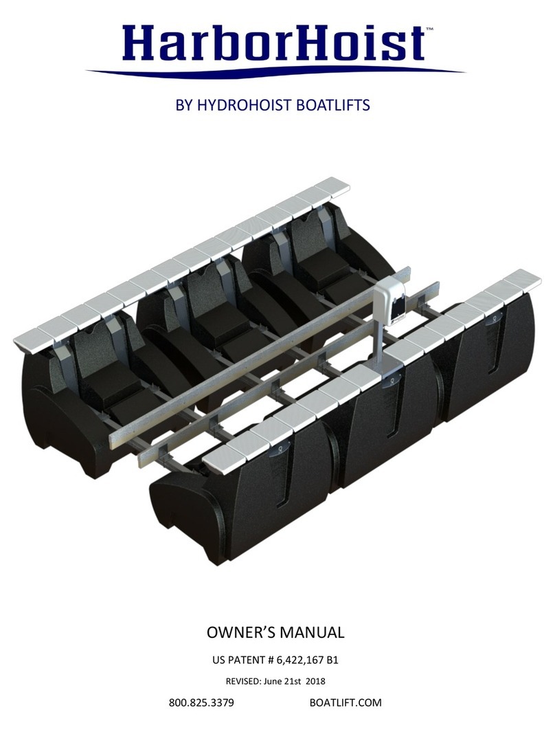
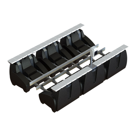
HydroHoist FM 6000 User manual
Other HydroHoist Lifting System manuals
HydroHoist
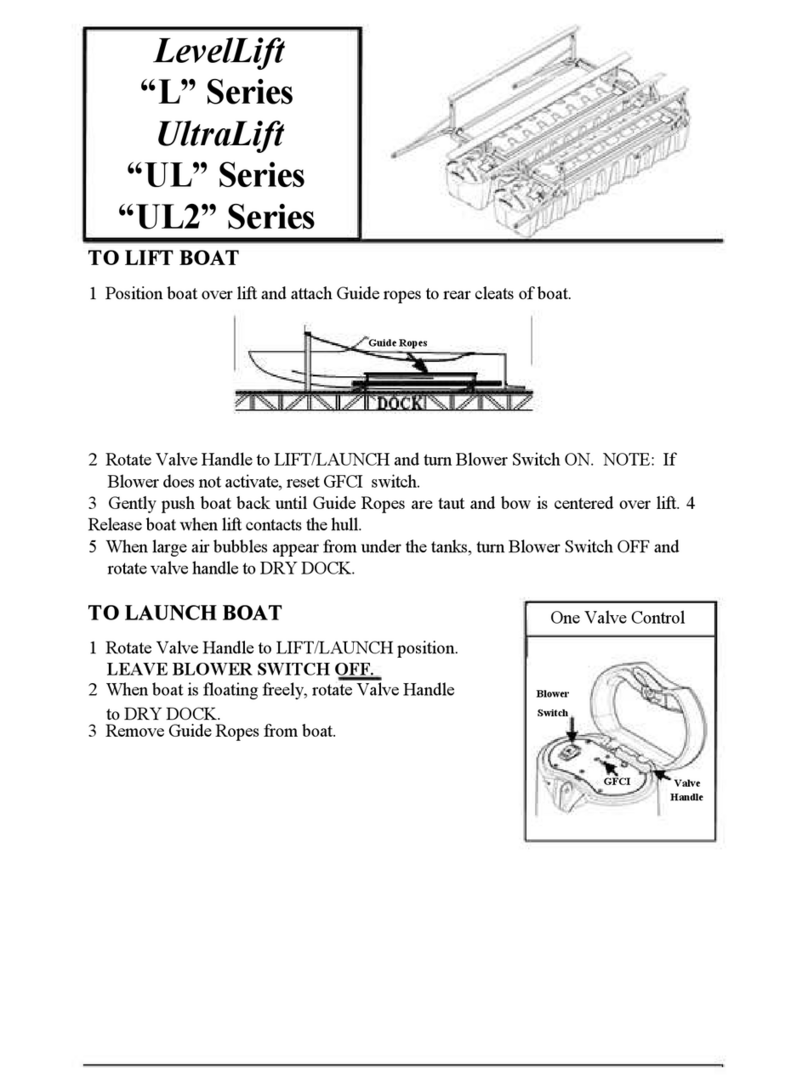
HydroHoist LevelLift L Series Quick start guide
HydroHoist
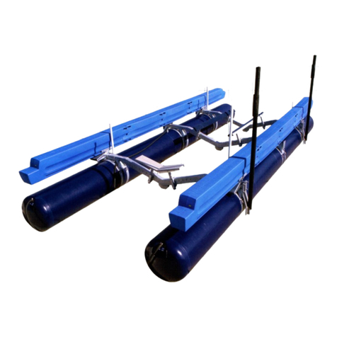
HydroHoist Side-Tie B Series User manual

HydroHoist
HydroHoist HydroPort EPIC User manual
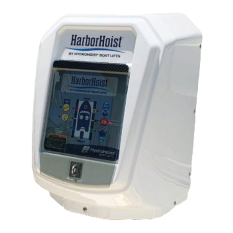
HydroHoist
HydroHoist HarborHoist Triton User manual

HydroHoist
HydroHoist UltraLift FRONT MOUNT Series User manual
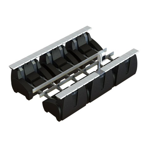
HydroHoist
HydroHoist HarborHoist HH-20,000 V-HULL V-FRAME User manual

HydroHoist
HydroHoist 4400 FM User manual
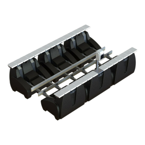
HydroHoist
HydroHoist HarborHoist Series User manual

HydroHoist
HydroHoist UltraLift Series User manual

HydroHoist
HydroHoist HarborHoist 4400 User manual
Popular Lifting System manuals by other brands

morse
morse 82H-124 Operator's manual

Braun
Braun NL955 Series Operator's manual

haacon
haacon 1889.10 quick start guide

Protekt
Protekt AT 252 instruction manual

R. Beck Maschinenbau
R. Beck Maschinenbau HS 600 operating manual

Nova Technology International, LLC
Nova Technology International, LLC NAS Series quick start guide

Genie
Genie Z-60/34 Operator's manual

Screen Technics
Screen Technics INTERFIT Vertical Up Lift instructions

Mortuary Lift
Mortuary Lift ULTIMATE 1000 instructions

Custom Equipment
Custom Equipment Hy-Brid 3 Series MAINTENANCE & TROUBLESHOOTING MANUAL

Custom Equipment
Custom Equipment Hy-Brid Lifts 2 Series Maintenance and troubleshooting manual

Hy-Brid Lifts
Hy-Brid Lifts HB-P3.6 MAINTENANCE & TROUBLESHOOTING MANUAL

BERG
BERG BeNomic EasyLeaf Technical manual

Powermate
Powermate LiftGate LG-3 Installation & operation manual

Snorkel
Snorkel TM12 Series Operator's manual

Terberg
Terberg OMNIDEKA Translation of the original instructions

Harmar Mobility
Harmar Mobility AL625 Installation & owner's manual

Rotary
Rotary SPO16 installation instructions
