Wiseair WAFS-104 User manual

User Manual
2021 Release 2
WiseAir Technologies India LLP
support@wiseair.asia +91 90477 78715
WAFS 104
THERMAL FLOW SENSOR
Page 1 of 24
MEASURE TO MANAGE
User
Manual for
Thermal
Mass
Flow Sensor
WAFS - 104

User Manual
2021 Release 2
WiseAir Technologies India LLP
support@wiseair.asia +91 90477 78715
Page 2 of 24
MEASURE TO MANAGE
TABLE CONTENTS
Section Contents Page No.
1
2
3
4
5
6
7
8
9
10
11
12
13
14
General Information
About WAFS-104 Thermal Mass Flow Sensor
What's in the Box?
Product Specifications
Installation - Mechanical
Installation - Electrical (Wiring)
Configuring Settings
System Settings
Communication Settings
Warranty
Calibration
Need Help
Technical Support
Commissioning Report
3
4
6
7
8
16
17
18
18
19
19
19
20
23
WAFS 104
THERMAL FLOW SENSOR

User Manual
2021 Release 2
WiseAir Technologies India LLP
support@wiseair.asia +91 90477 78715
Page 3 of 24
MEASURE TO MANAGE
Section 1 : General Information :
1.1 Please read this user manual in full and carefully observe the notes and
instructions before and during installation, operation and maintenance. The manufacturer
cannot be held liable for any damage which occurs as a result of non-observance or
noncompliance with this user manual.
Should the device be tampered with in any manner other than a procedure which is
described and specified in this manual, the warranty is cancelled and the manufacturer is
exempt from liability. The device is designed exclusively for the described application.
This user manual should be read carefully by the technician / qualified personnel and
the end user. Once you install, use or maintain this product, you accept that you have read,
understood and complied with this manual. This manual should be kept with the Flow Meter and
made available to relevant personnel as needed. WiseAir Endeavours to make changes to the
content of this Manual, and tries to ensure Correctness and well stated, but is not responsible for
Omissions or errors and the consequences caused thereby.
1.2 Compressed Air Safety
Any contact with quickly escaping air or bursting parts of the compressed air system
can lead to serious injuries or even death.
Do not exceed the maximum permitted pressure
Only use pressure tight installation material.
Avoid getting hit by escaping air or bursting parts.
The system must be pressure-less during maintenance work.
1.3 Electrical Safety
Any contact with energised parts of the product, may lead to an electrical shock which
can lead to serious injuries or even death.Consider all regulations for electrical installations.
The system must be disconnected from any power supply during maintenance work.
Any electrical work on the system is only allowed by authorised qualified personal.
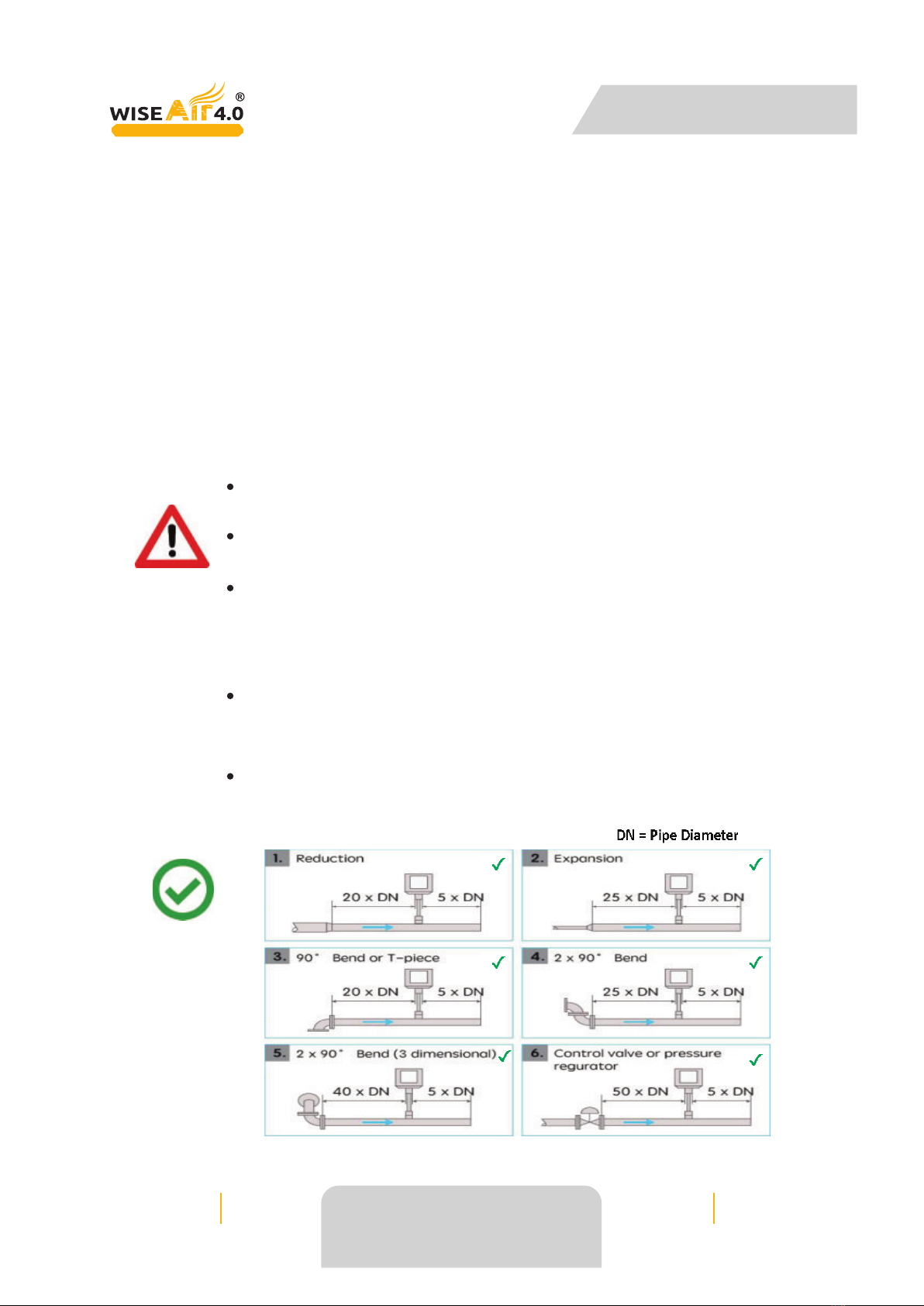
1.4 Installing the Flow Meter, Calibration & Maintenance
The product must be installed properly and frequently calibrated, otherwise it may
lead to the wrong measurement values, which can lead to wrong results.
Always Observe the Direction of Flow When installing the Sensor. The
Direction is Indicated on the Housing.
Do Not Exceed the Maximum Operation Temperature at the Sensors Tip.
Avoid Condensation on the Sensor Element as this will affect the accuracy
enormously.
Please observe national regulations before/during installation and
operation.
Do not disassemble the product.
Always use a spanner to mount the product properly
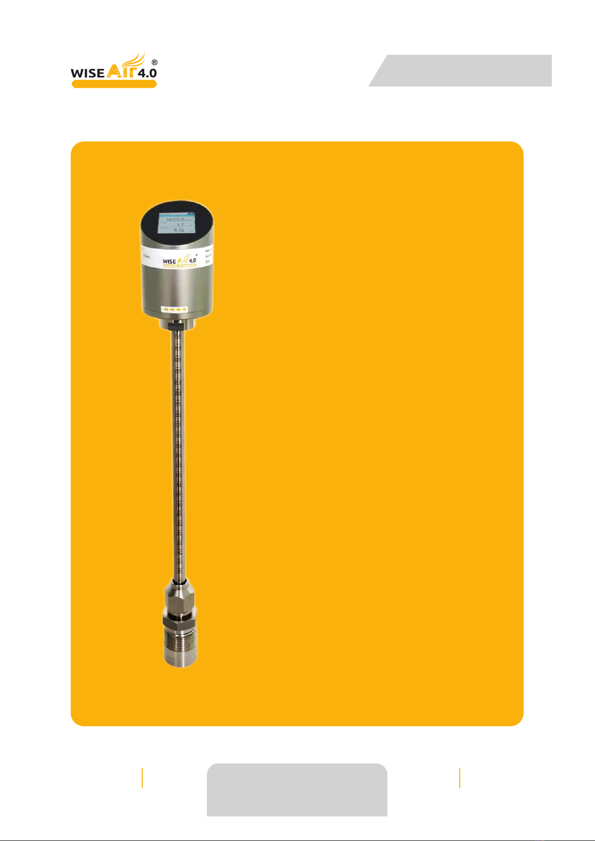
WAFS 104
THERMAL FLOW SENSOR

User Manual
2021 Release 2
WiseAir Technologies India LLP
support@wiseair.asia +91 90477 78715
Page 4 of 24
MEASURE TO MANAGE
1.5 Using the Flow Meter
Do not use this product in explosive areas.
Do not exceed the permitted operating parameters. Any operation exceeding
these parameters can lead to malfunctions and may lead to damage on the
instrument or the system.
Do not exceed or go below the permitted storage and operation temperature
and pressure.
This product should be maintained and calibrated frequently, at least every
2 years.
1.6 Storage and transportation
Make sure that the transportation temperature of the sensor is between
-10°C to 60 °C.
Storage temperature of the sensor is between -10 °C to 50 °C and the
humidity is <90%, no condensation.
Avoid direct UV and solar radiation during storage.
Section 2 : About WAFS -104 THERMAL MASS FLOW SENSOR
2.1 Importance of Flow Meters:
Flow meters are very popular for measuring compressed air systems. Depending on
where they are installed, flow meters can tell you the compressor output, system consumption,
peaks and troughs as well as average usage. When used well, flow monitoring can help keep
your system under control and highlight any unusual activity in your system.
2.2 Benefits of Monitoring Flow Include:
Improves system efficiency
Reduces system maintenance
Reduces operating and energy costs
Increases system understanding and operation
Identifies changes in system performance
Identifies non-productive air demand and leakage
Identifies peak and average demand
Different types of flow meters should be used depending on the specific location and
purpose. However, when it comes to compressed air, flow meters such as vortex or orifice plates
can create a pressure drop within the system, ultimately leading to increased operating cost of
the entire plant. As such, vortex or orifice plate flow meters are not recommended for
compressed air.
WAFS 104
THERMAL FLOW SENSOR

User Manual
2021 Release 2
WiseAir Technologies India LLP
support@wiseair.asia +91 90477 78715
Page 5 of 24
MEASURE TO MANAGE
2.3 Thermal Mass Flow Sensor :
Thermal mass flow meter measures gas mass flow based on thermal diffusion theory
and thermal principle of Newton. It has two RTDs as its sensor. One RTD is heated to T1 by a
heating power rate of P, the other is not heated but to measure the medium temperature T2. So
there is a temperature difference TD= T1-T2. TD reach max when mass flow is 0. When the mass
flow Q increases, the heat on T1 is taken away so the T1 decline and the TD become smaller. So
there is a certain relationship between heating power rate P, difference of temperature TD and
mass flow Q as below.
P/TD = K1 + K2 F(Q)^K3
The K1, K2 and K3 in above equation is constant related to the character of medium.
So the mass flow Q can be get through measuring the heating power rate P and difference of
temperature TD. In actual application, there are two different methods, one is consistent current
method and other one is consistent temperature method.
2.4 Key Features of thermal mass flow meter:
Insertion type sensor.
Independent of temperature and pressure change.
Ultra wide 1:2500 turndown ratio, measurement range from 0.1 Nm/s to
250 Nm/s.
2.8” ultra wide viewing angle LCD capacitive touch.
No moving parts, low pressure drop.
Standard RS485 Modbus RTU interface and 4-20mA current/pulse output.
WAFS 104
THERMAL FLOW SENSOR

User Manual
2021 Release 2
WiseAir Technologies India LLP
support@wiseair.asia +91 90477 78715
Page 6 of 24
MEASURE TO MANAGE
Section 3 : What's in the Box?
3.1 Each WAFS - 104 Flow Meter Unit comes with:
3.2 Optional Accessories
The following accessories are available for WAFS - 104 Flow Meter. Talk to your local
dealer for pricing and other accessories.
Y-type M12 connector for connecting multiple sensors
simultaneously via RS485
Smart Data Acquisition and Monitoring Software
1WAFS - 104 Flow Sensor
Power Adapter
2x5 Pin M12 Connector with
2 meter Cable
User Manual
Connection Spanner
Stainless Steel Nipple
Calibration Certificate
Stainless Steel ½" Ball Valve
2
3
4
5
8
7
6
WAFS 104
THERMAL FLOW SENSOR

User Manual
2021 Release 2
WiseAir Technologies India LLP
support@wiseair.asia +91 90477 78715
Page 7 of 24
MEASURE TO MANAGE
Section 4 : Product Specifications :
WAFS 104
THERMAL FLOW SENSOR

User Manual
2021 Release 2
WiseAir Technologies India LLP
support@wiseair.asia +91 90477 78715
Page 8 of 24
MEASURE TO MANAGE
4.1 Flow Range
Section 5 : Installation — Mechanical
Before installing the sensor, make sure it is rated for your system (refer to the
“Specifications” section above). We suggest purging the pipeline before installation to prevent
impurities from damaging the flow meter or blocking the pressure pipe.
WARNING!
Incorrect installation can damage the sensor or cause it to work incorrectly.
5.1 Step 1 - Find a Suitable Section of Horizontal Pipe
The Sensor Must be Installed:
on a horizontal pipe
upright, at 90° (+15°) to the pipe (ie vertically),
away from bends, edges, seams, changes in pipe size and other obstructions
(see Step 2 below)
after the first filter or water separator (ie the sensor can not be installed directly
on the outlet of the compressor)
Make sure the insertion location has enough room above the pipe to install the
sensor. If installing the sensor outdoor, protection from sun and rain is necessary.
WAFS 104
THERMAL FLOW SENSOR

User Manual
2021 Release 2
WiseAir Technologies India LLP
support@wiseair.asia +91 90477 78715
Page 9 of 24
MEASURE TO MANAGE
5.2 Install Vertically To Pipe
The sensor must be installed upright, at 90° +/- 15° (ie within 75° to 105° of vertical).
Installing the sensor at an angle can result in water accumulating in the shaft or head of the
sensor. This can damage the sensor and void the warranty.
5.3 Correct Installation
5.4 Incorrect Installation
Do NOT install the sensor on a vertical pipe, upside down or at an angle, as
shown below.
Do NOT let water get into the shaft or head of the sensor as this can damage
the sensor or result in incorrect readings.
Install the sensor after the dryer.
WAFS 104
THERMAL FLOW SENSOR

User Manual
2021 Release 2
WiseAir Technologies India LLP
support@wiseair.asia +91 90477 78715
Page 10 of 24
MEASURE TO MANAGE
5.5 Step 2 — Choose Insertion location away from obstacles
To achieve and maintain the accuracy stated in the technical data, the sensor must be
inserted vertically, on a straight horizontal pipe section away from bends, edges, seams, curve,
changes in pipe size, control valves, etc. The sensor cannot be installed directly on the outlet of
the compressor.
For best results, choose a Iong , absolutely straight, horizontal section of pipe that is
free of obstructions. Pipe obstructions (eg bends, edges, seams, curve, changes in pipe size,
control valves, etc) change the velocity of compressed air / asses and/or create turbulence near
the obstruction. Placing the sensor too close to the obstruction will result in inaccurate readings.
Make sure that the insertion location has enough straight pipe on either side of the
sensor, as shown in the diagram
WARNING! Inaccurate measurement may occur if the sensor is installed incorrectly
Pay careful attention to the distance between the sensor's inlet and outlet
sections and points of turbulence (eg bends, valves, etc)
Obstructions can cause counter-flow turbulence as well as turbulence in the
direction of the flow.
The sensor is for indoor use only. If installed in an outdoor installation, the
sensor must be protected from sun and rain.
The figure below shows the minimum distances (in multiples of pipe diameters (DNs))
that the sensor must be installed away from bends, changes in pipe size and other obstructions.
The inlet side of the sensor must be at least 20 to 50 times the pipe diameter
way from the obstruction (depending on the type of obstruction — see figure
below).
The outlet side of the sensor must be at least 5 times the pipe diameter away
from the obstruction.
Correct Installation
WAFS 104
THERMAL FLOW SENSOR

User Manual
2021 Release 2
WiseAir Technologies India LLP
support@wiseair.asia +91 90477 78715
Page 11 of 24
MEASURE TO MANAGE
Incorrect Installation
Examples
WAFS 104
THERMAL FLOW SENSOR

User Manual
2021 Release 2
WiseAir Technologies India LLP
support@wiseair.asia +91 90477 78715
Page 12 of 24
MEASURE TO MANAGE
5.5 Step 3 - Fixing the Ball Valve on the Pipe:
To install the sensor, you need a ball valve or a nozzle with the following
specifications:
The inner thread must be G 1/2"
The diameter of the hole must be > 13mm, otherwise the shaft can not
be inserted into the pipe.
WAFS 104
THERMAL FLOW SENSOR

User Manual
2021 Release 2
WiseAir Technologies India LLP
support@wiseair.asia +91 90477 78715
Page 13 of 24
MEASURE TO MANAGE
5.5 Step 4 — Insert Sensor and Align Tip With the Centre of the Pipe
Place O-Ring on sensor shaft gland nut.
Screw the sensor into the valve, then open the valve.
OD
2
5.5 Step 5 - Insert Sensor and Align Tip With the Centre of the Pipe
Use the depth scale on the sensor shaft to
place the tip of the sensor in the middle
of the pipe.
Once the tip is in the centre of the pipe, tighten
the gland nut to hold the sensor in place.
The Insertion Depth = x + y = +y
OD = outer diameter of pipe
Y = ball valve height.
WAFS 104
THERMAL FLOW SENSOR

User Manual
2021 Release 2
WiseAir Technologies India LLP
support@wiseair.asia +91 90477 78715
Page 14 of 24
MEASURE TO MANAGE
Correct Installation
Incorrect Installation
The Sensor tip must be in the center of the pipe / tube.
Note : Inaccurate measurement may occur if the sensor is installed incorrectly.
WAFS 104
THERMAL FLOW SENSOR

User Manual
2021 Release 2
WiseAir Technologies India LLP
support@wiseair.asia +91 90477 78715
Page 15 of 24
MEASURE TO MANAGE
Examples
5.5 Step 6 — Align the Sensor With Direction of Flow
The flow meter is not bidirectional. When installing and using the flow meter, please
pay attention to the direction of air flow and the alignment of the sensor.
The direction is flow is marked by 4 green arrows on the back of the
sensor and underneath the sensor.
Correct Installation
Incorrect Installation
The Sensor is aligned in the same direction as the gas flow.
Note : Inaccurate measurement may occur if the sensor is installed incorrectly
Use the alignment tool to align the sensor with the pipe. Ensure the arrows on the
sensor match the direction of flow.
WAFS 104
THERMAL FLOW SENSOR

User Manual
2021 Release 2
WiseAir Technologies India LLP
support@wiseair.asia +91 90477 78715
Page 16 of 24
MEASURE TO MANAGE
Section 6 : Installation - Electrical (Wiring)
The flow sensor is equipped with two M12 connector plugs - “A” and “B”. Cables are
connected to the sensor through the M12 connector plugs.
Do not screw the M12 connector using force. Otherwise, it may damage the
connection pins.
WAFS 104
THERMAL FLOW SENSOR

User Manual
2021 Release 2
WiseAir Technologies India LLP
support@wiseair.asia +91 90477 78715
Page 17 of 24
MEASURE TO MANAGE
Section 7 : Configuring Settings
MENU
Home
Settings
SUB MENU 1 SUB MENU 2 SUB MENU 3
Flow
Consumption
Velocity
Temperature
Pipe Diameter
Unit Setting
Normalization
RS 485 Setting
Baud Rate
Parity
Flow Setting
Velocity Setting
Consumption Setting
Normalized Temperature
Normalized Pressure
3 3
NM /hr NM /min
3
NM /sec NI/min
NI/sec NCFM
Kg/hr Kg/min
3
Kg/sec SM /hr
3 3
SM /min SM /sec
SI/min SI/sec
SCHM
1200 2400 4800
9600 14400 19200
38400 56000 57600
115200
None Odd Even
NM/sec NFT/sec
SM/sec SFT/sec
3 3
NM NFT Kg
3 3
SM SFT
Stop Bits 1 2
Response Delay
Device Address
Analog Setting
4-20 MA Channel Flow Velocity
Temperature
4-20 MA Scaling Low
4-20 MA Scaling High
Pulse Output
System Setting
Brightness Setting
Screen Timeout
System Information
15 Sec 30 Sec 1 M
2 M 5 M 10 M
Password
Advanced Setting
Gas Type
Air Oxygen
Nitrogen Hydrogen
Carbon dio.
Consumption
Velocity Offset Ratio
Velocity Filter Grad.
Change Password
WAFS 104
THERMAL FLOW SENSOR

User Manual
2021 Release 2
WiseAir Technologies India LLP
support@wiseair.asia +91 90477 78715
Page 18 of 24
MEASURE TO MANAGE
Section 8 : System Settings
Section 9 : Communication Settings
Default Modbus Settings
Settings can be changed to suit system requirment
WAFS 104
THERMAL FLOW SENSOR

User Manual
2021 Release 2
WiseAir Technologies India LLP
support@wiseair.asia +91 90477 78715
Page 19 of 24
MEASURE TO MANAGE
Section 10 : Warranty
Section 11 : Calibration
Section 12 : Need help?
WiseAir Technologies provides a 12-month warranty for all Flow Meters. The
warranty covers material and workmanship under the stated operating conditions from the date
of delivery. Please report any issues immediately and within the warranty time.
If faults occur during the warranty period WiseAir Technologies will repair or replace
the defective unit, without charge for repair labor and material costs but there is a charge for
other services such as labor to remove or reinstall the instrument, transport and Warranty
repairs do not extend the period warranty.
The following damage is excluded from this warranty:
Improper use and non-adherence to the user manual.
Use of unsuitable accessories. External influences (e.g. damage caused by
vibration, damage during transportation, excess heat or moisture).
The warranty is cancelled when one of the following situations occurs:
The user opens the measurement instrument without a direct request written in this
manual. Repairs or modifications are undertaken by third parties or unauthorized persons. The
serial number has been changed, damaged or removed.
The sensor is calibrated before delivery. The calibration date is printed on the
certificate which is shipped with the sensor.
Flow meters require calibration to remain accurate. The frequency of calibration
depends greatly on the level of contamination within your system. By using insertion style flow
meters wherever possible, you can install and remove them without the need for shutting the
system down, virtually eliminating any lost production time caused by periodic maintenance.
We recommend you calibrate the sensor every 2 years. The calibration is excluded from the
product warranty. For more information, please contact WiseAir Technologies.
Contact your local dealer.
Alternatively, contact
WiseAir Technologies
Asia
Tel. +91 - 090477 78715
Email : support@wiseair.asia
Europe
Ph : +45 36990422
E-mail : support wiseair.eu
WAFS 104
THERMAL FLOW SENSOR

User Manual
2021 Release 2
WiseAir Technologies India LLP
support@wiseair.asia +91 90477 78715
Page 20 of 24
MEASURE TO MANAGE
Section 13 : Technical Support
Questions :
I can't see all menu items
The touch screen doesn't work
Help! My sensor is in the wrong language.
My sensor isn't reading correctly
How do I clean the sensor?
13.1 I Can't See all Menu Items
On some menus, you will need to scroll up and
down to see all items. This is indicated by a
scroll bar on the right side of the screen.
13.2 The Touch Screen Doesn't Work
If the touch screen doesn't work:
Clean the screen
Make sure the Screen Lock is off.
If the lock screen symbol is
present, press the symbol, hold and drag it to
the right of the screen.
Use your finger to touch the screen.
The touch screen does not
work if you use finger nails or pens.
Try pressing harder, or softer
13.3 Help ! My sensor is in wrong language
If you need to change the language :
Step 1 - Unlock the Screen
If the lock Screen symbol
is Present, press the symbol,
hold and drag it to the right of the
screen.
If the screen lock symbol
is not present, skip this step.
Flyde
Hastighed
Forbrug
WAFS 104
THERMAL FLOW SENSOR
Table of contents
Other Wiseair Accessories manuals
Popular Accessories manuals by other brands

CALORIQUE
CALORIQUE Snow & Ice CM1020 installation manual

Victory
Victory VDW-24-4 manual

steute
steute RF 96 SDS SW868-NET Mounting and wiring instructions

Ellia
Ellia IMAGINE ARM-505 instruction manual

AQUANTIS
AQUANTIS MICROFREEZE user guide

Scame electrical solutions
Scame electrical solutions ADVANCE-GRP Series Installation, use and maintenance