Wisenet SPA-M1000 User manual

SPA-M1000
MICROPHONE
User Manual

Copyright
©2021 Hanwha Techwin Co., Ltd. All rights reserved.
Trademark
Each of trademarks herein is registered. The name of this product and other trademarks mentioned in this manual are the registered trademark of their
respective company.
Restriction
Copyright of this document is reserved. Under no circumstances, this document shall be reproduced, distributed or changed, partially or wholly, without formal
authorization.
Disclaimer
Hanwha Techwin makes the best to verify the integrity and correctness of the contents in this document, but no formal guarantee shall be
provided. Use of this document and the subsequent results shall be entirely on the user’s own responsibility. Hanwha Techwin reserves the right
to change the contents of this document without prior notice.
※Appearance, specication, etc. of the product is subject to change for performance improvements without prior notice.
The latest update is available on the ocial Hanwha Techwin website. (www.hanwha-security.com)
※The initial administrator ID is“admin”and the password should be set when logging in for the rst time.
Please change your password every three months to safely protect personal information and to prevent the damage of the information theft.
Please, take note that it’s a user’s responsibility for the security and any other problems caused by mismanaging a password.
Microphone
User Manual

English _3
!OVERVIEW
WARNING
TO REDUCE THE RISK OF FIRE OR ELECTRIC SHOCK, DO NOT EXPOSE THIS PRODUCT
TO RAIN OR MOISTURE. DO NOT INSERT ANY METALLIC OBJECT THROUGH THE
VENTILATION GRILLS OR OTHER OPENINGS ON THE EQUIPMENT.
Apparatus shall not be exposed to dripping or splashing and that no objects filled with liquids,
such as vases, shall be placed on the apparatus.
To prevent injury, this apparatus must be securely attached to the Wall/ceiling in accordance
with the installation instructions.
CAUTION
CAUTION
RISK OF ELECTRIC SHOCK.
DO NOT OPEN
CAUTION : TO REDUCE THE RISK OF ELECTRIC SHOCK.
DO NOT REMOVE COVER (OR BACK).
NO USER SERVICEABLE PARTS INSIDE.
REFER SERVICING TO QUALIFIED SERVICE PERSONNEL.
EXPLANATION OF GRAPHICAL SYMBOLS
The lightning flash with arrowhead symbol, within an equilateral triangle, is
intended to alert the user to the presence of “dangerous voltage” within the
product’s enclosure that may be of sufficient magnitude to constitute a risk of
electric shock to persons.
The exclamation point within an equilateral triangle is intended to alert the user to
the presence of important operating and maintenance (servicing) instructions in
the literature accompanying the product.
CAUTION
RISK OF EXPLOSION IF BATTERY IS REPLACED BY AN INCORRECT TYPE.
DISPOSE OF USED BATTERIES ACCORDING TO THE INSTRUCTIONS.
ATTENTION
IL Y A RISQUE D’EXPLOSION SI LA BATTERIE EST REMPLACÉE PAR UNE BATTERIE DE
TYPE INCORRECT.
METTRE AU REBUT LES BATTERIES USAGÉES CONFORMÉMENT AUX INSTRUCTIONS.
These servicing instructions are for use by qualified service personnel only.
To reduce the risk of electric shock do not perform any servicing other than that contained in
the operating instructions unless you are qualified to do so.
The ITE is to be connected only to (PoE/PoE+) networks without routing to the outside
plant.
The wired LAN hub providing power over the Ethernet (PoE/PoE+) in accordance with
IEEE 802.3af/at shall be a UL Listed device with the output evaluated as a Limited Power
Source as defined in UL60950-1 or PS2 as defined in UL62368-1.
Unit is intended for installation in a Network Environment 0 as defined in IEC TR 62102.
As such, associated Ethernet wiring shall be limited to inside the building.
overview

overview
4_ overview
IMPORTANT SAFETY INSTRUCTIONS
1. Read these instructions.
2. Keep these instructions.
3. Heed all warnings.
4. Follow all instructions.
5. Do not use this apparatus near water.
6. Clean the contaminated area on the product surface with a soft, dry cloth or a damp cloth.
(Do not use a detergent or cosmetic products that contain alcohol, solvents or surfactants or oil constituents
as they may deform or cause damage to the product.)
7. Do not block any ventilation openings, Install in accordance with the manufacturer’s instructions.
8. Do not install near any heat sources such as radiators, heat registers, stoves, or other apparatus (including
amplifiers) that produce heat.
9. Do not defeat the safety purpose of the polarized or grounding-type plug. A polarized plug has two blades
with one wider than the other. A grounding type plug has two blades and a third grounding prong. The wide
blade or the third prong are provided for your safety. If the provided plug does not fit into your outlet, consult
an electrician for replacement of the obsolete outlet.
10. Protect the power cord from being walked on or pinched particularly at plugs, convenience receptacles, and
the point where they exit from the apparatus.
11. Only use attachments/ accessories specified by the manufacturer.
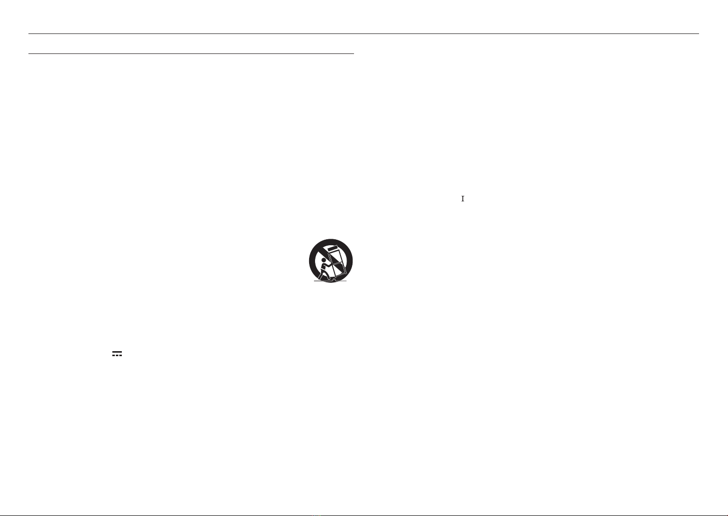
12. Use only with the cart, stand, tripod, bracket, or table specified by the manufacturer,
or sold with the apparatus. When a cart is used, use caution when moving the cart/
apparatus combination to avoid injury from tip-over.
13. To prevent injury, this apparatus must be securely attached to the Wall/ceiling in
accordance with the installation instructions.
14. Unplug this apparatus during lighting storms or when unused for long periods of time.
15. Refer all servicing to qualified service personnel. Servicing is required when the apparatus has been damaged
in any way, such as power-supply cord or plug is damaged, liquid has been spilled or objects have fallen into
the apparatus, the apparatus has been exposed to rain or moisture, does not operate normally, or has been
dropped.
16. This product is intended to be supplied by a Listed Power Supply Unit marked “Class 2” or “LPS” or “PS2”
and rated from PoE (48V ), 250mA.
17. This product is intended to be supplied by isolation power.
18. If you use excessive force when installing the product, the product may be damaged and malfunction.
If you forcibly install the product using non-compliant tools, the product may be damaged.
19. Do not install the product in a place where chemical substances or oil mist exists or may be generated. As
edible oils such as soybean oil may damage or warp the product, do not install the product in the kitchen or
near the kitchen table.
This may cause damage to the product.
20. When installing the product, be careful not to allow the surface of the product to be stained with chemical
substance.
Some chemical solvents such as cleaner or adhesives may cause serious damage to the product’s surface.
21. If you install/disassemble the product in a manner that has not been recommended, the production functions/
performance may not be guaranteed.
22. Do not install on a surface where it is exposed to direct sunlight, near heating equipment or heavy cold area.
23. Do not place this apparatus near conductive material.
24. Do not attempt to service this apparatus yourself.
25. Do not place a glass of water on the product.
26. Do not install near any magnetic sources.
27. Do not place heavy items on the product.
28. Please wear protective gloves when installing/removing the product.
The high temperature of the product surface may cause a burn.
29. This device has been verified using STP cable. The use of appropriate GND grounding and STP cable
is recommended to effectively protect your product and property from transient voltage, thunderstroke,
communication interruption.
30. In particular installation environments, there might be interference in radio communications.
When interference of electromagnetic waves occurs between the product and radio communication device, it
is recommended to keep a certain distance between the two or change the direction of the receiving antenna.
31. An apparatus with CLASS construction shall be connected to a MAINS socket outlet with a protective
earthing connection.
32. Batteries(battery pack or batteries installed) shall not be exposed to excessive heat such as sunshine, fire or
the like.
The battery cannot be replaced.
33. Disconnect the main plug from the apparatus, if it’s defected. And please call a repair man in your location.
34. Select an installation site that can hold at least 5 times the product’s weight.
35. Stuck-in or peeled-off cables can cause damage to the product or a fire.
36. For safety purposes, keep anyone else away from the installation site.
And put aside personal belongings from the site, just in case.
37. We do not guarantee the quality of third-party products (e.g. accessories) that you separately purchase.

English _5
!OVERVIEW
OVERVIEW
3
4Important Safety Instructions
6Features
7Checking the components
8Names and functions of each part
INSTALLING AND CONNECTING
10
10 Installation
11 Connecting to other devices
STARTING
12
12 Connecting to a PC
12 Access product
15 Logging in
ENVIRONMENT SETTINGS
16
16 Home Screen configuration
16 Maintenance
17 System management
19 Network settings
20 Time settings
USING THE MICROPHONE
21
21 Power on
22 Broadcasting
23 Using CP event button
23 Using VP event button
24 Using menu
CONTENTS

overview
6_ overview
FEATURES
~Paging communication over the network
You can broadcast a variety of messages, such as announcements to a designated area within the network,
using the paging system by connecting it to a network audio server or controller mode speaker.
~Gooseneck microphone
You can use the gooseneck microphone conveniently by adjusting its position flexibly to fit a user environment.
~Simple button operation
You can select the broadcasting area simply by using the buttons on the Number buttons or the ALL
button, etc., and you can select the operation method of the TALK button and CHIME button based on your
preferences.
~2.42 inch OLED display
Through the OLED display, you can monitor the current status of the product and prevent errors when entering
button inputs, such as when selecting a broadcasting area.
~Level meter with an LED display
You can intuitively monitor the current volume level through the sound level meter with an LED display.
~Monitoring speaker
You can monitor the current volume level using the monitoring speaker on the side of the product.
~Input/output control volume
You can adjust the input volume of the microphone, the volume of the monitor speaker and chime, and the
input volume of the connected external audio source.
~DC 24V power input
A DC 24V power input terminal provides a stable power supply while using an adapter.
~Power over Ethernet (PoE)
If you connect a PoE-enabled device to the NETWORK port of the product, power can be supplied without a
separate power connection.

English _7
!OVERVIEW
CHECKING THE COMPONENTS
Make sure all of the following components are included.
(Accessories may vary by sales region.)
1
2
3
4
5
1 2 3
4 5 6
7 8 9
*0 #
VOLUME
MONITOR
MIC
TALK
PUSH
MAXMIN
AUX
MAXMIN
CHIME
MENU
PRESET
PREV
NEXT
CHIME
POWER
-6dB 0dB
NETWORK
+3dB +6dB
MAXMIN
ALL
1
2
3
4
5
1 2 3
4 5 6
7 8 9
*0 #
VOLUME
MONITOR
MIC
TALK
PUSH
MAXMIN
AUX
MAXMIN
CHIME
MENU
PRESET
PREV
NEXT
CHIME
POWER
-6dB 0dB
NETWORK
+3dB +6dB
MAXMIN
ALL
M
`
The images used in the product manual may differ from the actual product.
This product is a network microphone that is to be connected to the controller device (e.g.,
audio server, speaker/audio module set to controller mode) of the network audio system.
To use the microphone, you must connect it to the network and register a device via a web-
based integrated control software and an RM source. You can set up your CP and VP
numbers in the Events & Preset menu.
There should be only one controller mode device in the broadcast system.
If there are multiple controller mode speakers or audio servers and they are registered as the
microphone more than once, proper broadcasting cannot be performed.
1
2
3
4
5
1 2 3
4 5 6
7 8 9
*0 #
VOLUME
MONITOR
MIC
PUSH
TALK
MAXMIN
AUX
MAXMIN
CHIME
MENU
PRESET
PREV
NEXT
CHIME
POWER
-6dB 0dB
NETWORK
+3dB +6dB
MAXMIN
ALL
< >
Network Microphone
Local PC
Network Audio Server
Network Speakers (wall-mount type)
Network Speaker (Controller Mode)
Network Speakers (ceiling-mount type)
Network Audio Module (Analogue Speaker)
<Local Network>

overview
8_ overview
NAMES AND FUNCTIONS OF EACH PART
Front
1
2
3
4
5
1 2 3
4 5 6
7 8 9
*0 #
VOLUME
MONITOR
MIC
TALK
PUSH
MAXMIN
AUX
MAXMIN
CHIME
MENU
PRESET
PREV
NEXT
CHIME
POWER
-6dB 0dB
NETWORK
+3dB +6dB
MAXMIN
ALL
ap o n
m
l
k
j
i
h
g
e f
b
c
d
Name Function Description
a
Microphone release button Releases the gooseneck microphone.
b
Microphone connection port Connects the gooseneck microphone.
c
Status indicator Indicates the settings and current status of the product.
d
CP event buttons This is a CP event number (1 - 5) input button set in the <
All Event & Preset List
> of
the controller device.
e
Number buttons
Buttons used to select a broadcast area or mode number.
This is also used as the VP event number button set in the <
All Event & Preset List
> of
the controller device.
f
TALK button The button used to start or end a broadcast with a microphone.
For information on how to set the TALK button, refer to "
Talk Type Settings
". (Page 24)
g
ALL button The button used to select all broadcast regions.
Name Function Description
h
CHIME button The button used to sound a chime to signal the start or end of a broadcast.
For information on how to set up a chime, refer to "
Chime Settings
". (Page 24)
i
NEXT button When entering numbers, if 8 or more numbers have already been entered, they cannot all
be displayed on a single screen, so this button is used to return to the previous page.
j
PREV button
When entering numbers, if 8 or more numbers have already been entered, they cannot all
be displayed on a single screen, so this button is used to return to the previous page.
*Used as the Exit button for the Menu screen.
k
PRESET button Button to switch to CP, Group, or Zone mode in the
<Talk Protocol>
menu.
l
MENU button
Use it to make settings for the TALK and CHIME buttons, or to check the product's
network or firmware information.
*The [
MENU
]button is also used as the Exit button for the Number input screen.
m
Level meter LED Measures and displays the current volume level.
n
Network status LED Indicates network connection status.
o
Power status LED Indicates power connection.
p
Monitor speaker/AUX/Chime
volume dial
Controls the volume of the monitor speaker, the input volume of the connected external
audio source, and the chime volume.

English _9
!OVERVIEW
Rear
DC 24V
POWER RESET NETWORK PoE AUX IN MIC VOL
MAXMIN
a b c d e
Name Function Description
a
POWER input terminal Supplies DC 24V power by connecting to the supplied power adapter.
b
RESET switch
A button that returns the product settings to the factory default values. Press the button
for approximately 12 seconds to reset and reboot the product.
J Do not disconnect the power until product resetting is complete. Doing so may cause
malfunctions.
It will take more than 10 minutes to reboot after resetting the product.
c
NETWORK terminal
Connects network cable.
The microphone can be used when broadcasting through the integrated control software
of the controller device within the same network.
When connected to a PoE device (switching hub), power can be supplied without a
separate power connection.
d
AUX IN port Receives sound by connecting to an external audio source via an RCA cable.
e
MIC VOL dial A dial that adjusts the microphone input volume level

10_ installing and connecting
installing and connecting
INSTALLATION
Precautions Before Installation
~Be careful that cables do not become stuck in the wrong places and that the covering of electric wires is
not damaged, as this can cause product damage or fire.
~If the product is forcibly assembled by applying excessive force, the product may be damaged.
~Adjust the microphone volume to the minimum before plugging it into the power source.
Connecting to the Gooseneck Microphone
Align the 3 pins on the bottom of the gooseneck microphone with the hole of the connection port, then push
it in until you hear a click sound.
1
2
3
4
5
1 2 3
4 5 6
7 8 9
*0 #
VOLUME
MONITOR
MIC
TALK
PUSH
MAXMIN
AUX
MAXMIN
CHIME
MENU
PRESET
PREV
NEXT
CHIME
POWER
-6dB 0dB
NETWORK
+3dB +6dB
MAXMIN
ALL
MIC
PUSH
Disconnecting from the Gooseneck Microphone
Disconnect the gooseneck microphone from the device while pressing the <PUSH>button on top of the
gooseneck microphone.
DC 24V
POWER RESET NETWORK 1 PoE AUX IN
MIC VOL
MAX
MIC
PUSH

English _11
!INSTALLING AND CONNECTING
CONNECTING TO OTHER DEVICES
DC 24V
POWER RESET NETWORK PoE AUX IN MIC VOL
MAXMIN
External audio source
Power
Router or switching hub
(PoE supported)
J
`
When connecting to each device, be sure to power off the connected device before connecting.
Connecting to a Network
Connect the router or switching hub to the NETWORK port of the product using a network cable.
Network Connection to Power
Connect the router or switching hub using a network cable that provide PoE to the NETWORK port of the
product.
J
`
For PoE, use equipment that supports the IEEE802.3af standard.
`
If you connect to a PoE-supported switching hub, you can use the product without connecting a separate power
source.
`
To connect to the product's network, refer to "starting." (Page 12)
Connecting to Power
Connect the supplied power adapter's connector to the product's power input (DC 24V), and then connect
the power cord to the power adapter.
Network Cable Specifications
Item Specifications Remark
Connector RJ45 (10/100BASE-T)
Ethernet 10/100Base-T
Cable Category 5e
Max Distance 100 m DC resistance ≤ 0.125 Ω/m
PoE Support IEEE 802.3af

12_ starting
starting
You can set the product’s network environment according to the user’s network connection
configuration.
To change your product’s network configuration settings, follow these instructions to access
the product.
CONNECTING TO A PC
The PC should be connected to the same network as the product when accessing the product for the first time.
Use a network cable to connect the product’s NETWORK port to the switching hub that is connected with the
PC.
1
2
3
4
5
1 2 3
4 5 6
7 8 9
*0 #
VOLUME
MONITOR
MIC
TALK
PUSH
MAXMIN
AUX
MAXMIN
CHIME
MENU
PRESET
PREV
NEXT
CHIME
POWER
-6dB 0dB
NETWORK
+3dB +6dB
MAXMIN
ALL
M
`
Connect the supplied DC power cable to receive power, or connect a switching hub that supports PoE or PoE+
ACCESS PRODUCT
Various functions, including maintenance and environment settings, are available on the product website.
1. Set an IP address to 192.168.1.x, the same band as the product, in the network property of the PC.
(e.g. 192.168.1.100)
2. Run a web browser on the PC.
M
`
An available web browser is Google Chrome (Version 99.0.4844.82 or higher).
Google Chrome is available at www.google.com/chrome.
`
It can be used in Chrome as it is a supported web browser. For the computer OS, it can be used in Windows 10 or
Mac 10.15 (Catalina) or 11 (Big Sur).
Product validation was performed on Windows 10 21H2 and the Mac 10.15.7 and 11.6 versions.
3. The initial IP address of all products is 192.168.1.99.
Before installing the product, it is recommended to set a static IP address for separate products.
M
`
If multiple products are connected concurrently to the same switch hub with the initial IP addresses, the web page
cannot distinguish the IP addresses, resulting in failing to set passwords.
`
Use Device Manager to set the initial password and IP address to use.

English _13
!STARTING
Registering using Device Manager
If the product is connected to a network which includes a computer where the device manager is installed, you
can search products, set up passwords, change IP addresses, upgrade firmware, and access web pages.
Please refer to the manual of the Device Manager Program for more information.
M
`
The Device Manager Program ( ) is available on the official Hanwha Techwinwebsite (http://www.hanwha-
security.com) by clicking <Technical Support> - <Online Tool>.
1. When you connect the product to the switch hub, its IP address is 192.168.1.99, and its status
information is queried as <Need PW>.
2. Select one or multiple products and set a password to use for each product.
~Set a password in the [Credential] menu and press [Search] on the list screen. Then, the status
information is queried as <Login Fail> or <Login OK>.
~Depending on the number of products selected or the network conditions, you may encounter the
<Connect Fail> message. The password setting and [IP Assign] function will run normally irrespective
of the indicated status.
~For the rest of the products that are queried as <Need PW>, select them and set passwords for them.
~If they are not queried as <Need PW>, run <New Project>
;
<Search> and set the passwords after
being queried as <Need PW>.
J
`
A password should contain 8 or more characters, and if it contains fewer than 9 characters, then a combination of
3 or more English uppercase/lowercase letters, numbers, or special characters must be used. If it includes 10 to 16
characters, a combination of 2 or more types must be used.
`
It is recommended not to use the same character repeatedly or consecutive keyboard inputs as passwords for
enhanced security.
3. Select a product to set its IP address, and enter the IP address to use (e.g., Set Static IP).
When you select products one by one
~Select <Assign the following IP address> from the [IP Assign] menu, then set its IP address.
~The DNS server address is automatically set as the product’s initial DNS address (DNS1 8.8.8.8,
DNS28.8.4.4).
When you select multiple products
~Select <Assign the following IP address> from the [IP Assign] menu. Then apply the starting address
in the range of IP addresses to be assigned.
J
`
When you select <Obtain an IP address automatically (DHCP)> from the [IP Assign] menu, the DHCP IP address
is automatically assigned.
`
The HTTP port supports only the number 80, and the VNP and RTSP ports are not used in the network audio
product.

starting
14_ starting
4. When you press [Search] on the list screen, it can be queried with the set IP address and <Login OK>.
~If its status is not queried with <Login OK>, please log in on the [Credential] menu to be queried with
<Login OK>.
J
`
If you apply the product password in <System> ;<Device Default Credential Setting> in the device manager,
it is automatically queried as <Login OK> even when you search for it as a new project or re-execute the device
manager.
M
`
You can update to the latest firmware for the product using the device manager.
`
The network audio product does not support the download the latest firmware’s download function.
`
Please download the latest firmware (modelname_version.imkp) to your PC from the Hanwha Techwin website
(http://www.hanwha-security.com).
1.
When selecting firmware for each product and running [Upgrade], the status will change to <50%> from
<Login OK>.
2.
When the firmware update is completed and the system is rebooted, the status will change to <Please wait
until the program starts.>. After it reaches 100%, it will change to <Success>
3.
If you update multiple products at the same time, the update will proceed sequentially by four units at a time.

English _15
!STARTING
Registering with the product’s initial IP address
If you connect only one product to the switch hub, it is possible to set up the password even on the web
page.
1. Enter the product’s initial IP address into the web browser’s address bar.
2. The admin account password must be registered when accessing the product for the first time.
When the <Change Password> window appears, please enter a new password.
J
`
A password should contain 8 or more characters, and if it contains fewer than 9 characters, then a combination of
3 or more English uppercase/lowercase letters, numbers, or special characters must be used. If it includes 10 to 16
characters, a combination of 2 or more types must be used.
`
It is recommended not to use the same character repeatedly or consecutive keyboard inputs as passwords for
enhanced security.
3. A product login screen appears after successfully setting the password.
LOGGING IN
Use the password set for the admin account.
1. Enter “admin” in the <ID>field.
2. Enter a password in the <Password> field.
3. Click the [Login] button to move to the Home screen of the product.
After 30 minutes of inactivity on the website, you will be automatically logged out.
J
`
If you forget the password, the product has to be initialized by pressing the RESET button for about 12 seconds.
Therefore, make sure to write your password down or remember it.
If you have already logged in, the system can be initialized in the <Environment Setting> ;<System
Management> menu of the web page.
`
Do not disconnect the power until the system initialization is complete after pressing the [RESET] button of the
product or during product resetting. It will take more than 10 minutes to reboot after resetting the product.
M
`
To change the network settings according to the user’s network connection configuration, use the <Network
Setting> function in <Environment Setting>. (Page 19)
`
Available accounts are divided into admin, setup, user, and guest by access authority level. Go to <Environment
Setting> ;<System Management> ;<Change Password> to change the passwords of each account. (Page
17)
`
A maximum of five users can log in to the product at the same time. The “Exceed the maximum user ” screen
will appear if there is an attempt to log in while the maximum number of users are logged in, and it will show the
currently connected PC IP addresses.

environment settings
16_ environment settings
environment settings
HOME SCREEN CONFIGURATION
If you connect to the product using a web browser, you can check the system management, network settings,
time settings, logs, etc.
Getting to Know the Home Screen
a cb d
fg e
Name Function Description
a
Home Goes to the Home screen.
Maintenance Logs generated in the product can be checked.
Environment Setting You can set up the System Management, network, and time information.
b
Product Model Name Displays the device's model name.
c
Product Information The IP address, product name, product location, and firmware version are displayed.
d
Connected Account/Login Shows a connected account and its login status.
e
Time Information The connection time to the web page menu, product cumulative operating time, and product time
will be displayed.
f
Language Shows the language options supported on the website. (Korean, English supported)
g
Go to the Official Website
If you click <Hanwha>, the screen will move to the Hanwha Techwin Official Website.
MBefore using the product, please check the latest firmware version on the Hanwha Techwin
website (http://www.hanwha-security.com). Download and update it if it is necessary.
M
`
The optimal monitor resolution is 1920x1080.
MAINTENANCE
View Log
Logs generated in the product can be checked.
The log items are different for each product, and they are recorded when the log operation occurs.
3
5
4
1. Click <Maintenance> ;<View Log> on the Home screen.
2. The action log history for the device is shown by item.
The Log menu will appear on the View Log when its function is activated.
3. If you click the [Receive Logs] button, the file can be downloaded in the HTML format.
Check HTML files using Google Chrome.
4. If you click the [Delete Logs] button, all logs displayed on the screen will be deleted.
5. The Output Unit, Auto Update, Update Cycle, and Scroll Mode can be set.
If you activate <Auto Update>, logs will be displayed in accordance with the <Update Cycle> on the
screen.
M
`
If you set <Scroll Mode> to automatic, the screen will be moved downward to show recent logs.
`
Press the [$/%] button to view the upper and lower logs.

English _17
!ENVIRONMENT SETTINGS
SYSTEM MANAGEMENT
Various functions are available, including System Upgrade, Change Password, System Check, Restart, and Reset.
Upgrading the System
1. Click <Environment Setting> ;<System Management> on the Home screen.
2. Click the [Upload] button in <System Upgrade>.
3. Select the upgrade file (model name_version.imkp) that you downloaded from the official Hanwha Techwin
website (http://www.hanwha-security.com) in advance and click [Open].
4. Click [Apply] to start System Upgrade. Click <OK> when the “System Restart” window appears after up
to five minutes.
J
`
If you close the web browser or move to another menu before the “Restart the Program” message pops up, it may
not be updated.
`
Do not disconnect the power in the middle of a system upgrade. Doing so may cause malfunctions.
5. It will take up to 10 minutes to upgrade the system and reboot the product.
The software version information of the product is available in the upper-right corner of the Home screen.
Changing the Password
You can change the passwords of each account.
1. On the Home screen, click <Environment Setting> ;<System Management>.
2. By clicking <Destination Account> from <Change Password>, select the account you want to change
and set the password.
3. Click the [Apply] button after entering a new password in the two input fields.
4. The admin account can be changed if you enter the previous password.
If you forgot the previous password, the product has to be initialized, and the passwords for all the
accounts will be initialized during the process.
5. The password of the setup, user, and guest accounts can be set, changed, or reset from the admin
account if they are forgotten.
Viewing the supported menu by account
To prevent any confusion due to arbitrary changes to the settings and to continue stable maintenance of the
system, access rights are differentiated by account, and all restricted features for each account are disabled
on the screen.
- admin: The system management, network settings, time settings, and log history can be viewed.
- setup, user: The log history can be viewed.
- guest: The product information can be checked on the home screen.

environment settings
18_ environment settings
Unlock Account
For all accounts except the admin account, if you enter the wrong password more than 5 times when logging
in, the account will be locked for 30 seconds and you will not be able to log in.
The admin account can reset the number of retries by checking the number of login retries for each account
and whether the account is locked.
1. On the Home screen, click <Environment Setting> ;<System Management>.
2. Click [Reset] after checking the locked account on <Account lock status> The lock icon is changed to
unlocked and the number of retries for the account is reset.
Setting the System Check Time
Sets the time for the system check. The system reboots automatically at the set time every day.
1. On the Home screen, click <Environment Setting> ;<System Management>.
2. Set the time to start checking in <System Check Settings>
3. Click [Apply] after clicking the [ ] button of <Activation>.
4. The system will be checked and be rebooted at the set time; it will take approximately 5 minutes.

English _19
!ENVIRONMENT SETTINGS
Restarting System
You can restart the system without disconnecting the power when a system reboot is needed.
1. On the Home screen, click <Environment Setting> ;<System Management>.
2. Click the [Apply] button in <System Restart>.
3. Click <OK> when the system restarting window appears.
It will take approximately 5 minutes to reboot the system.
Resetting the System
Initializes every system setting to the factory default values.
An IP address of the product is also initialized to the initial status, which is 192.168.1.99.
1. On the Home screen, click <Environment Setting> ;<System Management>.
2. If you click the [Apply] button of the <All> item on <Factory Default Setting>, all set values will be reset,
and if you click the [Apply] button of the <Network status maintain> item, all set values except for
network information will be reset.
3. Click <OK> when the factory default window appears. Product initialization starts.
4. Click <OK> when the system start window appears on the web browser.
J
`
Do not disconnect the power until the factory default settings are restored.
It will take more than 10 minutes to reboot after resetting the product.
• When the system initialization is completed, previously registered product information should
be deleted from the controller mode speaker or audio server (SPA-S1000), and you must
register if you wish to use the product.
• As the log information will be deleted when the product’s system is initialized, please
download it in advance.
NETWORK SETTINGS
You can change the network settings according to the user’s network connection configuration.
1. On the Home screen, click <Environment Setting> ;<Network Setting>.
~On the <Common network configurations setting>, the <Device Name> is displayed as <Name> on
the device manager’s query list.
~You can enter the location of installation in <Device Location> in <Common network configurations
setting> (e.g. 6th floor, Main Building)
~You can enter the IP address, subnet mask, gateway, DNS 1 and DNS 2 server addresses for the product
by selecting <User Setting> in <Network Setting>.
`
MAC address: The unique physical address of the product. (e.g. Starts with 00:1d:1d.)
`
IP address: Enter the IP address available in your network band.
`
Subnet mask: The subnet mask of the set IP address is indicated.
`
Gateway: The gateway of the set IP address is indicated.
`
DNS 1 server, DNS 2 server: Enter the primary DNS address and secondary DNS address.
~The IP, subnet mask, gateway, DNS 1 and DNS 2 server addresses for the product will be allocated
automatically from the DHCP server by selecting <DHCP Setting> in <Network Setting>.
~Click [Apply] to apply the set network information to the product.
~Click [Initialize] to return to the most recent status before changing settings.
J
`
The system restarts automatically if the network settings are changed.

environment settings
20_ environment settings
TIME SETTINGS
Set the time and date accurately or it may cause problems in operating the broadcast.
1. On the Home screen, click <Environment Setting> ;<Time Setting>.
~The current time is set if you select GMT of your location on <Standard Time Zone>
~For the local network which is not connected to the external Internet, select <User Setting> in <Time
Setting> and enter the time manually to use it.
~If it is connected to the external Internet, select <Auto Configuration> in <Time Settings> to synchronize
the time to the standard time of the time server.
~For the domain address in the <Time Server Address> input field, use time.google.com / time.apple.com
/ pool.ntp.org / north-america.pool.ntp.org / time.bora.net / clock.isc.org.
Please check if the domain address provides time information which reflects Daylight Saving Time.
~<Next Synchronization Time> automatically changes from the previously synced time every 8 hours.
~Click [Synchronization Now] to synchronize the time to the time server.
2. Click [Apply] to apply the set Time and Date information.
J
`
If the product is used in a local network environment without an external Internet connection, the time information
may become wrong due to the product’s accumulated time errors. To accurately schedule the broadcast time, it is
recommended to install a separate time server device which uses GPS signals, or enter its audio server IP address
(SPA-S1000) in the <Time Server Address> field of other products to synchronize the time information of the
audio servers.
`
If the product is used in a local network environment without the external Internet connection, Daylight Saving Time
is not automatically reflected as it is not synchronized with an external time server.
In countries where Daylight Saving Time is applicable, it is recommended for the system administrator to use the
product by changing the time manually for the start and end dates of the Daylight Saving Time.
Other manuals for SPA-M1000
1
Table of contents
Other Wisenet Microphone manuals