Wisi OH 38 User manual

WISI COMPACT HEADEND
OH 38
Betriebsanleitung
Operating instructions
• Modulation von 2 A/V-Signalen in 2 analoge
TV-Kanäle
• Multi-Standard
• Stereofähiger Restseitenbandmodulator,
in 250-kHz-Schritten unabhängig einstellbar
• Audio-/Videoschnittstellen in BNC/Cinch
• Ausgangsfrequenzbereich 45–862 MHz
• Modulationof2A/Vsignalsto2analog
TVchannels
• Multistandardoperation
• Stereocapablevestigialsidebandmodulator,
independentlyadjustablein250kHzsteps
• Interfaceforaudio/videowithBNC/Cinch
• Outputfrequencyrange45–862MHz
411 982 c

- 2 -
Headend OH 41 (OK 41 A) (Zubehör) / Headend OH 41 (OK 41 A) (Accessory)
Left Right
Down
Up
W I S I H E A D E N D
O H 5 0 V 1 . 0 0
Stand by
Betriebsspannung am Grundgerät angeschlossen und „Initialisierung der Module“ abgeschlossen.
Handset an Buchse des Grundgerätes einstecken. Durch Drücken einer Taste gelangt man in
das Modul- oder System-Menü.
Stand by
Supply voltage connected to basic unit and wait till mode “Initialising the modules” has finished. Plug
the handset into the socket on the basic unit. Press any key to call the module menu or
System menu.
Modul-Menü / Module menu
Modul 1 OH 79/Module 1 OH 38
Parameter-Menü / Parameter menu
Modul 2 OH 85 /Module 2 OH 85 Channel
F-Out
Parameter-Untermenü/Parameter sub-menu
826.000
Modul 14 OH 88 H/ Module 14 OH 88 H
Modul-Menü / Modul menu
▲▼ Tasten / keys — Modul 1… 14 wählen/Select module 1...14
▶Taste/keys — Weiter zum Parameter-Menü /Move to parameter sub-menu
◀Taste/keys — Zurück / Back
Hinweis: Nach erfolgter Programmierung ziehen Sie
das Handset ab.
Note: After programming disconnect the handset.

- 3 -
Headend OH 41 (OK 41 A) (Zubehör) / Headend OH 41 (OK 41 A) (Accessory)
Parameter-Menü / Parameter menu
▲▼ Tasten / keys — Parameter wählen / Select parameter
▶Taste/keys — Weiter zum Parameter-Untermenü/Move to parameter sub-menu
◀Taste/keys — Zurück /Back
Parameter-Untermenü / Parameter sub-menu
◀▶ Tasten / keys — Zu ändernde Stelle wählen
Cursor blinkt unter der Stelle z.B. 1894
Bei Überschreiten des dargestellten Zahlenbereiches, zurück zum
Parameter-Menü
Select the digit to be changed
Cursor blinks below the digit, e.g. 1894
If the permissible range is exceeded, the unit returns to the parameter menu
▲▼ Tasten / keys — Wert ändern z.B. 1894 in 1834
Change the value, e.g. change 1894 to 1834
Speichern / Saving data
Autom. nach Verlassen des Parametermenüs oder ca. 60 Sekunden nach der letzten Eingabe.
Data are saved automatically after leaving the parameter, or 60 seconds after the last entry.

- 4 -
Bedienung / Instructions
Ausgangsdämpfungssteller
5 dB.............................0–15 dB in 1-dB-Schritten
Output attenuator
5 dB.............................0–15 dB in 1-dB-steps
Out-Att
Eingangsimpedanz Audioeingang
15 kΩ/ 600 Ω..............15 kΩoder 600 Ω
Input impedance audio input
15 kΩ / 600 Ω..............15 kΩor 600 Ω
A-Imp
F-Out Ausgangsfrequenz
471,25 .........................45,00–862,00 in 0,25 MHz
Output frequncy
471,25 .........................45,00–862,00 in 0,25 MHz
A-Level Audiosignal Pegelanpassung
+6… -6........................Pegelanpassung an Eingangspegel
Audio signal level adjustment
+6… -6........................Level adjustment to input level
A-Mode Art des generierten Audioausgangssignals
mono...........................Als Audiosignal wird mono generiert
stereo ..........................Als Audiosignal wird stereo generiert
dual .............................Als Audiosignal wird dual generiert
Mode of the audio output signal
mono...........................Audio signal is generated in mono
stereo ..........................Audio signal is generated in stereo
dual .............................Audio signal is generated in dual tone mode
Channel Kanalauswahl zur Einstellung
A.................................Oberer Eingang ist angewählt
B..................................Unterer Eingang ist angewählt
Channel selection for setting
A.................................Upper input is selected
B..................................Lower input is selected

- 5 -
Bedienung / Instructions
TP-Gen Testbildgenerator Ausgangssignal
off ...............................Testbild aus
on................................Testbild ein
Test pattern generator output signal
off ...............................Test pattern off
on................................Test pattern on
TV-Std TV-Standard des generierten Ausgangssignals
B/G ..............................alle Audiosignalarten sind zulässig
D/K..............................alle Audiosignalarten sind zulässig
I...................................Audiosignal stereo oder dual wird auf mono
umgestellt
L..................................wie bei I
M................................wie bei I
Dieses Menü ist nur im Kanal A verfügbar. Der TV-Standard des Kanales B
wird auf den gleichen Wert wie Kanal A gesetzt.
TV standard of the generated output signal
B/G ..............................any audio signal is permitted
D/K ..............................any audio signal is permitted
I...................................stereo or dual tone will be changed to mono
L..................................stereo or dual tone will be changed to mono
M................................stereo or dual tone will be changed to mono
This menue is only available for channel A. TV standard for channel B is set
to the same value as channel A.
V-Gain Eingangsverstärkung Videoeingang
fixed ............................fester Videoeingangspegel
AGC ............................automatische Videopegelregelung aktiv
Gain video input
fixed ............................fixed video input level
AGC.............................automatic gain control is active
ModOut Modulation des Ausgangssignales
on................................Der Ausgangskanal wird duch Wahl von „off“
off ...............................komplett ausgeschaltet
Modulation of the output signal
on................................By selecting the value „off“ the complete output
off ...............................channel will be switched off

- 6 -
Bedienung / Instructions
OH 38 Modul Bootloader-Version
V1.16 Hier wird die Bootloader-Version des Modules aus-
gegeben.
OH 38 module bootloader version
V1.16 It displays the bootloader version of the module.
BL-Ver
OH 38 Modul Hardware-Version
V1.00 Hier wird der Hardwarestand des OH 38 Modules
ausgegeben. Wird vom Software-Update benötigt.
OH 38 module hardware version
V1.00 It displays the hardware version witch is needed
for software updates.
HW-Ver
OH 38 Modul Software-Version
V1.23 Hier wird die Softwareversion des OH 38 Modules
dargestellt. Diese ändert sich geg. Nach einem
Software Update.
OH 38 module software version
V1.23 It displays the software version of the module. It
may change in case of a software update.
SW-Ver

- 7 -
Bedienung / Instructions
OH 38 Modul Update
no Durch Wahl von „yes“ kann hier gezielt ein
yes Software-Update an dem gewählten OH Modul
durchgeführt werden.
Insert USB Stick USB Stick mit OH 38 Software in OH 50 USB-
Anschluss einstecken.
V1_59.bin_ Es wird immer die Software mit der
höchsten Versionsnummer angezeigt. Durch die
„Up“ „Down“ Tasten kann, wenn vorhanden,
aber auch eine andere Version ausgewählt werden
Die Versionen sind aufsteigend sortiert. Durch
Drücken der Rechts-Taste wird die Version für das
Update ausgewählt.
Start Update:Yes Nun bei Start Update „Yes“ wählen und mit der
V1_59.bin „Rechts-Taste“ bestätigen. Das Update wird dann
gestartet. Mit „No“ wird das Update der Modul-
software übersprungen.
Hinweis: Liegen den Update-Dateien auch
Erweiterungsupdates bei werden diese ebenso
angezeigt. Der Updatevorgang erfolgt wie bereit
beim Modulupdate beschrieben
OH 38 module update
no A controlled software update of the selected
yes module can be done by selecting “yes”.
Insert USB Stick Connect a USB-stick with the OH 38 software to
the USB-connector.
V1_59.bin_ It displays the software with the highest version
number first. Other versions can be selected with
the “Up” and “Down” keys. The versions are
sorted in ascending order. The selection of the
version can be done by the “right”-key.
Start Update:Yes Now select Start Update ‚yes‘, and confirm it
V1_59.bin with the “right”-key. The update will be started.
Selecting “no” skips the update of the module soft-
ware.
Note: If in the Update files extention updates are available
they will be also displayed.
The update procedure is the same as described in
the module update.
Update

- 8 -
Technische Daten / Specifications
Eingang / Input
Video Eingangsimpedanz / Video input impedance 75 Ω
Video Eingangspegel / Video input level 1 Vss ± 0,4 V
Video Eingangsbandbreite / Video input bandwidth 20 Hz – 5 MHz
Audio Eingangsimpedanz / Audio input impedance 600 Ω / 15 kΩ
Audio Eingangspegel / Audio input level (for nom. deviation) -4 dBm / 1 kHz
Audio Pegelbereich / Audio level range +6 dB ... -6 dB
Audio Eingangsbandbreite / Audio input bandwidth 40 – 15000 Hz
Ausgang / Output
Ausgangsimpedanz / Output impedance 75 Ω
Ausgangfrequenzbereich / Output frequency range 45 – 862 MHz
Frequenzschritte / Frequency steps 250 kHz
Frequenzstabilität / Stability of output frequency ± 30 kHz
Ausgangskanal Bandbreite / Output channel bandwidth 7/8 MHz
Ausgangspegel / Output level (1dB steps) 90 – 105 dBµV
TV-Normen / TV-standards B/G, D/K, I, L, M
Audio-Format / Audio format Mono, Stereo, Dual
Gruppenlaufzeit / Group delay (-0,5….4,43 MHz) < 80 ns
S/N Video / S/N video (CCIR-rec. 567-1) > 57 dB
S/N Audio / S/N audio (color test pattern) > 50 dB
Amplitudengang / Stability of output level ± 1,5 dB
Störabstand / Spurious
innerhalb Kanal / inside TV-channels > 55 dB
ausserhalb Kanal / outside a TV-channel > 55 dB
Allgemeine Daten / General specifications
Abmessungen / Dimensions 220 (253*) x 105 x 29,5 mm
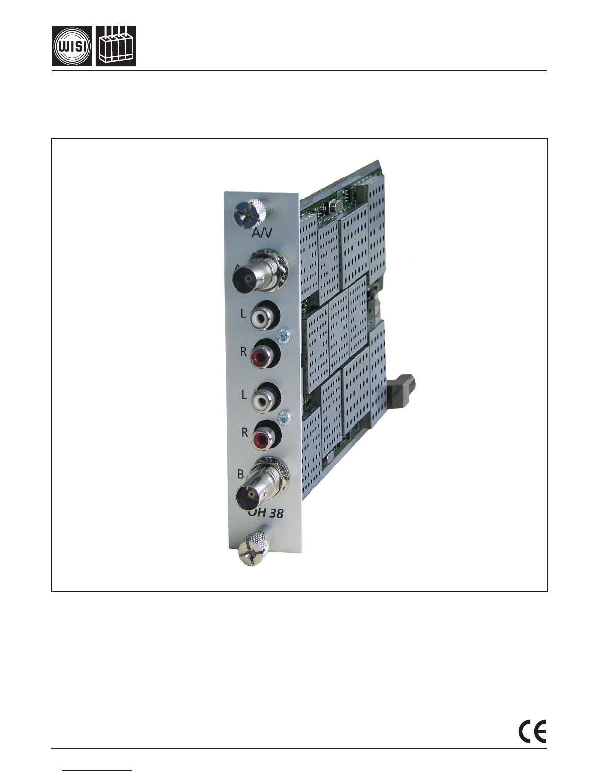
Anschlüsse / Connectors *with F-connector
Video 2 x BNC
Audio L/R 4 x Cinch
RF-output 1 x F-connector
Power Connector on board
Control Connector on board
Stromaufnahme (ohne CAM-Modul oder LNB-Versorgung) /
Current consumption (without CAM module or LNB-supply) 0,80 A/12,5 V
Leistungsaufnahme / Power consumption <10 W
Betriebstemperaturbereich / Operating temperature range -20 °C to + 55 °C
Solltemperaturbereich / Nominal temperature range +5 °C to +55 °C

- 9 -
Umschaltung Normal-Modus und Macrovision-Modus /
Switching from normal mode to Macrovision mode
Normal-Modus > Jumper X8 und X9 sind rechts gesteckt (siehe rote Markierung)
Normal mode > Jumper X8 and X9 plug right side (see red marking)
Macrovisions-Modus > Jumper X8 und X9 sind links gesteckt (siehe grüne Markierung)
Macrovision mode > Jumper X8 and X9 plug left side (see green marking)
Hinweis: Im Macrovisions-Modus ist die Video-AGC deaktiviert!
Remark: In Macrovision mode the Video-AGC is deactivated!
OH38 switching from normal mode to Macrovision mode
Normal mode Jumper X8 and X9 plug right side (see red marking)
Macrovision mode Jumper X8 and X9 plug left side (see green marking)
Remark: In Macrovision mode the Video-AGC is deactivated
M. Tammen Niefern, 11.10.2012

- 10 -

- 11 -

WISI Communications GmbH & Co. KG
Empfangs- und Verteiltechnik
Wilhelm-Sihn-Straße 5–7
75223 Niefern-Oeschelbronn, Germany
Tel.: +49 72 33-66-292, Fax: 66-320,
E-mail: info@wisi.de, http://www.wisi.de Technische Änderungen und Druckfehler vorbehalten!
TechnicalModicationsreserved.WISIcannotbeheld
liableforanyprintingerror.
12/12
Other Wisi Recording Equipment manuals
Popular Recording Equipment manuals by other brands

Toa
Toa RXA-212 Operating instructions manual

FieldServer
FieldServer SlotServer LonWorks Open Interface instruction manual

InCarTec
InCarTec 29-UC-050-REN2 quick start guide

Siemens
Siemens SINAMICS S120 Installation and start-up manual

Cadenceberge
Cadenceberge CAD-HV-HCA12 user manual

M-Audio
M-Audio Digipatch 12x6 manual