Witt hrp 5040 User manual

MONTAGE- UND BETRIEBSANLEITUNG HRP OPERATION & SERVICE MANUAL
INHALTSVERZEICHNIS CONTENTS
1. EINLEITUNG .........................................................................
2
1. INTRODUCTION ...................................................................
2
1.1 VERWENDUNGSZWECK................................................
2
1.1 INTENDED USE...............................................................
2
1.2 SICHERHEITSBESTIMMUNGEN ....................................
2
1.2 SAFETY REQUIREMENTS .............................................
2
1.3 SICHERHEITSHINWEISE................................................
3
1.3 SAFETY ADVICE .............................................................
3
1.4 HAFTUNGSAUSSCHLUSS .............................................
3
1.4 DISCLAIMER ...................................................................
3
2. GEWÄHRLEISTUNGSBESTIMMUNGEN ............................
4
2. TERMS OF WARRENTY.......................................................
4
3. TECHNISCHE INFORMATION .............................................
5
3. TECHNICAL INFORMATION................................................
5
3.1 TYPENBEZEICHNUNG ...................................................
5
3.1 DESCRIPTION OF TYPES ..............................................
5
3.2 LIEFERUMFANG .............................................................
5
3.2 SCOPE OF DELIVERY ....................................................
5
3.3 BESTELLANGABEN ........................................................
5
3.3 ORDERINFORMATION ...................................................
5
3.4 NORMEN UND BESCHEINIGUNGEN.............................
5
3.4 CODES / CERTIFICATES / APPROVALS.......................
5
4. TECHNISCHE DATEN ..........................................................
6
4. TECHNICAL DATA ...............................................................
6
4.1 ALLGEMEINE DATEN .....................................................
6
4.1 GENERAL INFORMATION ..............................................
6
4.2 ELEKTRISCHE DATEN ...................................................
6
4.2 ELECTRICAL DATA.........................................................
6
4.3 MATERIALIEN..................................................................
7
4.3 MATERIALS .....................................................................
7
4.4 DRUCKBEREICHE ..........................................................
7
4.4 PRESSURE RANGE........................................................
7
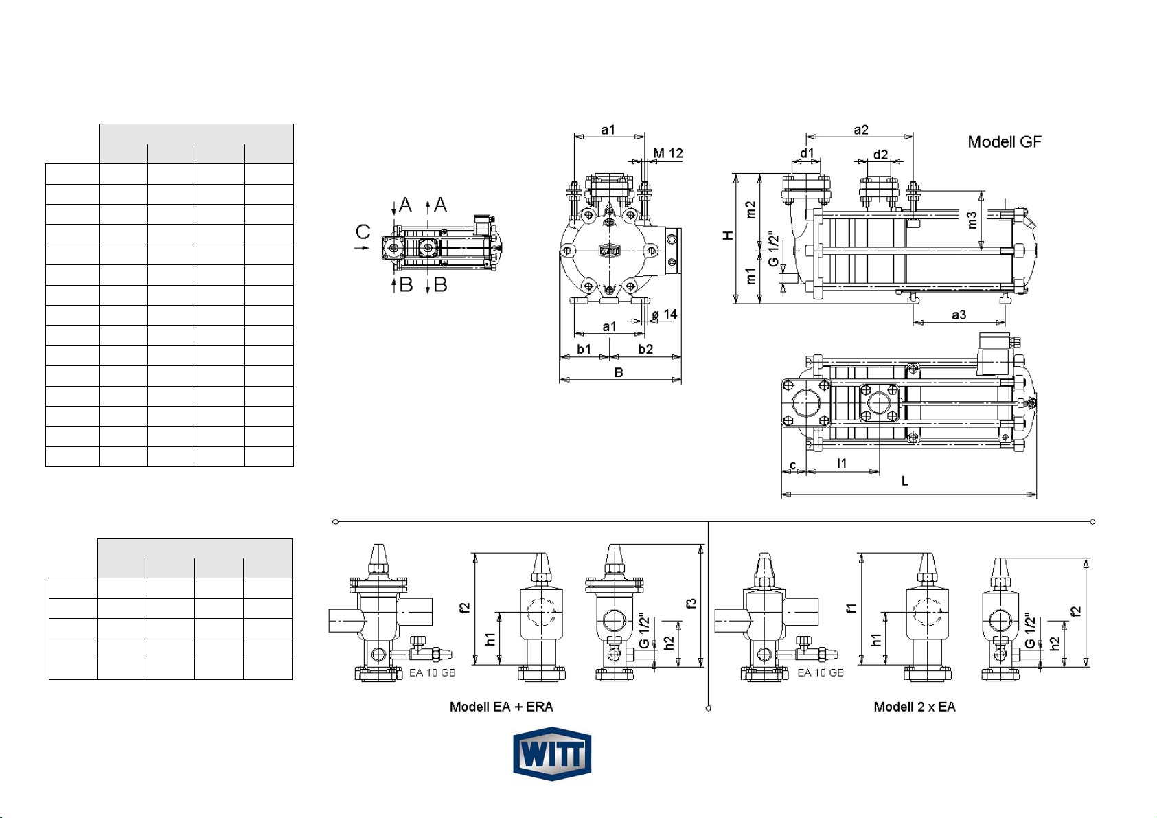
4.5 ABMESSUNGEN..............................................................
8
4.5 DIMENSIONS...................................................................
8
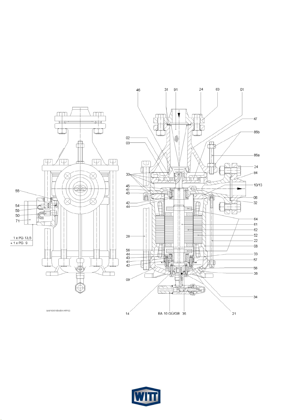
4.6 TEILELISTE....................................................................11 4.6 PARTS LIST................................................................... 11
4.7 SCHNITTZEICHNUNG...................................................1
2
4.7 SECTIONAL VIEW OF THE PUMP ...............................1
2
4.8 FUNKTIONSBESCHREIBUNG ......................................1
4
4.8 DESCRIPTION OF OPERATION...................................1
4
4.9 KENNLINIEN-VERLAUF ................................................1
4
4.9 PERFORMANCE CHARACTERISTIC TABLE .............. 1
4
5. PLANUNGSHINWEISE .......................................................1
5
5. APPLICATIONS ..................................................................1
5
5.1 ALLGEMEINES ..............................................................1
5
5.1 GENERAL ......................................................................1
5
5.2 BESTIMMUNG DER FÖRDERMENGE .........................1
6
5.2 DETERMINATION OF THE REQUIRED FLOW ............1
6
5.3 ANPASSEN AN DIE ANLAGENBEDINGUNGEN..........1
7
5.3 ADAPTATION TO PLANT REQUIREMENTS................ 1
7
6. INSTALLATIONSVORSCHRIFTEN....................................1
8
6. INSTALLATION INSTRUCTIONS ...................................... 1
8
6.1 PUMPENANORDNUNG.................................................1
8
6.1 PUMP ARRANGEMENT ................................................ 1
8
6.2 PUMPENANSCHLUSS ..................................................1
8
6.2 PUMP CONNECTION....................................................1
8
6.3 GESTALTUNG DES PUMPENZULAUFS ......................1
9
6.3 DOWNLEG DESIGN ...................................................... 1
9
6.4 PUMPENDRUCKLEITUNG............................................2
0
6.4 PUMP DISCHARGE LINE..............................................2
0
6.5 ELEKTRISCHER ANSCHLUSS / ABSICHERUNG........2
0
6.5 SAFETY AND ELECTRICAL INFORMATION ...............2
0
7. MONTAGE UND BEDIENUNG ...........................................2
7
7. INSTALLATION AND APPLICATION ................................2
7
7.1 MONTAGEVORBEREITUNG.........................................2
7
7.1 PREPARING THE PUMP FOR INSTALLATION ...........2
7
7.2 MONTAGE DER PUMPE ...............................................2
7
7.2 MOUNTING INSTRUCTIONS........................................2
7
7.3 VORBEREITUNG DER INBETRIEBNAHME .................2
8
7.3 PRIOR TO COMMISSIONING .......................................2
8
7.4 INBETRIEBNAHME........................................................2
9
7.4 COMMISSIONING PROCEDURE ................................. 2
9
7.5 NORMALBETRIEB.........................................................2
9
7.5 DURING NORMAL OPERATION................................... 2
9
7.6 PUMPE IM STILLSTAND (STAND-BY) .........................2
9
7.6 PUMP STANDSTILL (STAND-BY).................................2
9
8. WARTUNG UND INSTANDHALTUNG...............................3
0
8. SERVICE AND MAINTANANCE......................................... 3
0
8.1 AUSBAU DER PUMPE ..................................................3
0
8.1 REMOVING A PUMP ..................................................... 3
0
8.2 VERSAND DER PUMPE................................................3
0
8.2 SHIPPING OF THE PUMP............................................. 3
0
8.3 ALLGEMEINE HINWEISE..............................................31 8.3 GENERAL ADVICE........................................................31
8.4 REPARATUREN AN DER PUMPE ................................31 8.4 REPARING A PUMP......................................................31
8.5 BESONDERE HINWEISE ..............................................3
2
8.5 WARNINGS....................................................................3
2
Hersteller / manufacturer
TH. Witt Kältemaschinenfabrik GmbH
Lukasstrasse 32
52070 Aachen, Germany
Tel. +49-241-18208-0 * Fax. +49-241-18208-49
Angaben gültig ab dem 1.11.2001
Alle Rechte vorbehalten.
Es gelten unsere Liefer- und Montagebedingungen 558 und 188.
Data valid from 1.11.2001.
All rights reserved, subject to alterations without notice.
Our terms of delivery 558 and 188 are valid for all sales.

HERMETISCHE KÄLTEMITTELPUMPE
HERMETIC REFRIGERANT PUMP HRP
Montage- und Betriebsanleitung 98/37/EG Installation- and operating instructions
Fig.1a : HRP 5040
Fig. 1b: HRP 3232
1. EINLEITUNG 1. INTRODUCTION
Bitte lesen Sie die komplette Betriebsanleitung sorgfäl-
tig, bevor Sie die Pumpe auswählen, in Gebrauch neh-
men oder Wartungsarbeiten durchführen wollen.
Please read the entire manual careful before selecting,
installing, commissioning and servicing the pump.
1.1 VERWENDUNGSZWECK 1.1 INTENDED USE
Die WITT Hermetische Kältemittelpumpe Typ HRP ist aus-
schließlich zur Förderung eines Kältemittels im Siedezu-
stand bestimmt.
The WITT hermetic refrigerant pump type is designed to
deliver exclusively refrigerant liquid at its boiling point.
Sie ist gekennzeichnet mit der Typenbezeichnung und den
Anwendungsgrenzen für Druck und Temperatur.
Die Kältemittelpumpe weist Sicherheitsmerkmale auf, die
insbesondere dem Austritt von Ammoniak vorbeugen: So ist
z.B. auch der Wicklungsraum für den Nenndruck der Pumpe
ausgelegt. Bei einer Leckage des Spaltrohres kann daher
kein Kältemittel austreten, auch nicht durch das
Anschlusskabel!
The pump is labelled with model and design limitation for
pressure and temperature.
The HRP refrigerant pump is designed with safety fea-
tures, which ensures security from the escape of ammo-
nia; in the event the stator can leaking the pump body and
the complete motor housing is designed to 25 bar pres-
sure to contain high pressure refrigerantRefrigerant will
not escape from the pump or through the cable connec-
tions.
Die Leistungsdaten der Pumpe werden unter Kap.4, „Tech-
nische Daten“ angegeben.
Performance data of the pump are to be found in chapter
4 Technical data.
1.2 SICHERHEITSBESTIMMUNGEN 1.2 SAFETY REQUIREMENTS
Sämtliche beschriebenen Arbeiten an der Kältemit-
telpumpe dürfen nur von sachkundigem, im Um-
gang mit Kälteanlagen geschultem Personal
durchgeführt werden, das die einschlägigen Vor-
schriften zur Erstellung und Wartung von Kältean-
lagen kennt. Auch die Sicherheitsvorschriften hin-
sichtlich des Umgangs mit Kältemittel sind zu be-
achten, insbesondere das Tragen der persönlichen
Schutzbekleidung und einer Schutzbrille.
All of the following specified work must be car-
ried out by knowledgeable personnel experi-
enced in installation and service of refrigeration
systemsAll personnel must be familiar with the
national legal requirements and safety regula-
tions. All safety regulations and codes of prac-
tice concerning the use of refrigerants must be
adhered to, with special attention paid to p
tection clothing and wearing of safety glas
ro-
ses.
Reparatur- und Wartungsarbeiten dürfen nur bei
Stillstand der Kältemittelpumpe und abgeschalteter
Energieversorgung durchgeführt werden.
Service and maintenance only be carried out
when when the pump is stopped and the power
supply disconnected
2

Die angegebenen Temperatur- und Druckangaben
dürfen auf keinen Fall überschritten werden. .
Under no circumstances are the indicated tem-
perature- and pressure limitations to be ex-
ceeded.
Achtung! Dem Inhalt dieser Betriebsanleitung ist
unbedingt Folge zu leisten! Abweichender Einsatz
schließt eine Haftung und Gewährleistung durch
den Hersteller aus!
Important! The content of this manual must be
adhered to. Deviation from the specified condi-
tions will make any claim for liability or warrenty
void.
1.3 SICHERHEITSHINWEISE 1.3 SAFETY ADVICE
Die Pumpe wurde zum Einsatz in industriellen Kälteanlagen
mit Pumpenbetrieb entwickelt.
The pump is designed for use in industrial refrigeration
systems of primary refrigerant.
Die Motor- und Lagerkühlung wird durch verdampfendes
Kältemittel gewährleistet. Der entstehende Dampf wird
druckseitig abgeführt. In Relation zur Kälteleistung ist die
elektrische Leistungsaufnahme der Pumpe sehr gering.
Evaporating refrigerant is used to cool motor and bear-
ings. Any gas that forms in the pump is discharged to the
pressure side. The electrical power consumption of the
pump is low in relation to the refrigeration capacity, due
to the effect of the latent heat of the liquid being utilised
Es ist wichtig, dass die vorliegende Betriebsan-
leitung auch wirklich den zuständigen Perso-
nen bekannt ist.
It is very important that everybody respon-
sible for the safe operation and maintenance
of the plant reads this manual.
Sollten sich trotzdem einmal Schwierigkeiten einstellen,
wenden Sie sich bitte an unseren Kundendienst, der Ihnen
gerne behilflich sein wird.
I you have any problems please do not hesitate to call
our service department, our staff will be glad to assist
you.
Stolperstellen, - wie z.B. Kabel etc.-, sind zu vermeiden
oder, wenn nicht vermeidbar, mit entsprechendem zweifar-
bigem Klebeband (Warnbalken) zu kennzeichnen.
Avoid any tripping obstacle at ground levels, e.g. cable.
If you cannot avoid such obstacles they should be
marked with two-coloured warning tape (warning sign).
Bei Wartungs- und Instandsetzungsarbeiten gelöste
Schraubenverbindungen stets festziehen!
Retighten all screw connections after maintenance and
repair work.
Ist die Demontage von Sicherheitseinrichtungen beim Rüs-
ten, Warten und Instandsetzen erforderlich, soll unmittelbar
nach Abschluss der Arbeiten die Remontage und Überprü-
fung der Sicherheitseinrichtungen erfolgen!
If you have to disassemble any safety devices for main-
tenance and repair make sure that upon completion of
said work the re-assembly and proper functioning is
checked.
1.4 HAFTUNGSAUSSCHLUSS 1.4 DISCLAIMER
Auch bei bestimmungsgemäßer Verwendung können Ge-
fahren für Leib und Leben des Benutzers oder Dritter bzw.
Beeinträchtigungen der Maschine und anderer Sachwerte
entstehen.
Even when using the pump for the intended purpose it
cannot be entirely excluded that a danger remains for
the life of the user
Übersetzungen werden nach bestem Wissen durchgeführt.
Eine irgendwie geartete Haftung für Übersetzungsfehler
können wir nicht übernehmen.
Translations are carried out to the best of our knowl-
edge. We are unable to accept any liability for translation
errors.
Gegenüber Darstellungen und Angaben dieser Betriebsan-
leitung sind technische Änderungen, die zur Verbesserung
der Kältemittelpumpe notwendig werden, vorbehalten.
We reserve the right to change descriptions, graphs or
other statements, which are required for technical devel-
opment of the refrigerant pump.
3

2. GEWÄHRLEISTUNGSBESTIMMUNGEN 2. TERMS OF WARRENTY
Zur Vermeidung von Unfällen und zur Sicherung der optiona-
len Leistung dürfen an der Kältemittelpumpe weder Verände-
rungen noch Umbauten vorgenommen werden, die durch die
TH. WITT KÄLTEMASCHINENFABRIK GMBH nicht aus-
drücklich schriftlich genehmigt worden sind.
Diese Betriebsanleitung enthält die international genormten
SI-Maßeinheiten.
Alle Angaben und Hinweise für die Bedienung und Instandhal-
tung dieser Kältemittelpumpe erfolgen unter Berücksichtigung
unserer bisherigen Erfahrungen und Erkenntnissen nach
bestem Wissen.
In order to avoid accidents and ensure optimum per-
formance, no modifications or conversions may be
carried out to the refrigerant pump without the explicit
written approval by TH. WITT KÄLTEMASCHINEN-
FABRIK GMBH.
These instructions are based on internationally
standardised SI units of measurements.
All data and information on the operation and mainte-
nance of the refrigerant pump is provided based on our
extensive experience and to the best of our technical
knowledge.
Eine Haftung oder Gewährleistung ist ausgeschlossen,
wenn:
• die Hinweise und Anweisungen der Betriebsanleitung nicht
beachtet werden,
• die Kältemittelpumpe einschließlich zugehöriger Einrichtun-
gen fehlerhaft bedient wird bzw. deren Handhabung nicht
dem vorgeschriebenen Ablauf entspricht,
• die Kältemittelpumpe entgegen ihrer Bestimmung zweckent-
fremdet genutzt wird,
• Schutzeinrichtungen nicht benutzt oder außer Funktion
gesetzt werden,
• Funktionsänderungen jeder Art ohne unsere schriftliche
Zustimmung durchgeführt werden,
• die einschlägigen Sicherheitsbestimmungen nicht beachtet
werden,
• die Kältemittelpumpe einschließlich Filter und der zugehöri-
gen Sicherheits-Einrichtungen unsachgemäß (zeitlich wie
auch in der Ausführung) gewartet wird (das schließt auch
die Verwendung vorgeschriebener Ersatzteile ein).
Our liability or warranty is excluded, if:
• information and instructions in the operating manual
are ignored,
• the refrigerant pump including accessories is oper-
ated incorrectly or is installed contrary to these instal-
lation instructions
• the refrigerant pump is used for applications other
than that for which it was intended,
• safety devices are not used or disconnected
• there have been modifications made without written
approval
• the safety regulations are not adhered to
• the refrigerant pump including its filters and required
safety devices has not been maintained or repaired
correctly with respect to frequency or competence
this includes the use of approved spare parts.
Mit dem Öffnen der Pumpe während der Garantiezeit
gehen sämtliche Gewährleistungansprüche verloren!
Stets sollte die Einsendung in das Herstellerwerk oder die
Bestellung eines Austauschexemplares bevorzugt werden.
Opening the pump within the warranty period will
void all implied or explicit guarantees!
Always return the pump to the supplier for repair or
order an exchange pump.
Bei Austausch von Teilen bzw. für die Ersatzteilbeschaffung
sind nur vom Hersteller freigegebene Originalersatzteile zu
verwenden. Betriebsmittel sind gemäß den Angaben der
Betriebsanleitung einzusetzen.
When exchanging any parts respective spare parts
only genuine spare parts are to be used. Statements in
this manual shall also apply to any service fluids.
4

3. TECHNISCHE INFORMATION 3. TECHNICAL INFORMATION
3.1 TYPENBEZEICHNUNG 3.1 DESCRIPTION OF TYPES
Derzeit sind vier Baugrößen der Hermetischen Kältemittel-
pumpe lieferbar: HRP 3232, HRP 5040, HRP 5050 und HRP
8050. Eine größere HRP 10080 ist in Planung.
Die Typenbezeichnung HRP steht für Hermetische Radial
Pumpe. Dabei geben die ersten beiden Ziffern der nachfol-
genden Zahlenkombination die Nennweite des Saug- und die
beiden letzten Ziffern die Nennweite des Druckanschlusses
an.
Four hermetic pump types are available: HRP3232,
HRP5040, HRP 5050 and HRP8050. A larger size
HRP 10080 is on the way.
"HRP" means "Hermetic Radial Pump" The numbers
give the inlet and outlet pipe connection size in DN; the
first two digits give the size of the suction connection
while the last two digits give the size of the discharge
connection.
3.2 LIEFERUMFANG
• Pumpe komplett mit Spaltrohrmotor, Spitzsieb und
Gegenflanschen (Modell GF)
• Außerdem gehört zur HRP 3232 ein Ablassventil EA 10
GÜGB (PN 40)
3.2 SCOPE OF DELIVERY
• All HRP pumps, model GF, are complete with canned
motor, conical strainer and counter flanges only.
• for HRP 3232 additional oil drain valve type EA 10
GUB (PN 40) is included.
Optionaler Lieferumfang
• 2 x EA: Pumpe mit saugseitigem und druckseitigem Ab-
sperrventil), druckseitig mit Entlüftungsventil (Manomete-
ranschluß) und Nocken für Strömungswäch-
ter/Differenzdruckschalter
• EA + ERA: Pumpe mit saugseitigem Absperrventil und
druckseitigem absperrbarem Rückschlagventil, druckseitig
mit Entlüftungsventil (Manometeranschluß) und Nocken für
Strömungswächter/Differenzdruckschalter
• Thermistor Auslösegerät INT 69
Optional Equipment
• 2 x EA: with stop valves on suction side and dis-
charge side; discharge side with vent valve (pressure
gauge connection) and socket for flow switch
/differential pressure switch
• EA + ERA: with suction valve and discharge
valve/nonreturn valve discharge side with vent valve
(pressure gauge connection) and socket for flow
switch /differential pressure switch
• PTC motor control INT 69
3.3 BESTELLANGABEN
Bei Bestellung der Pumpe sind folgende Daten anzugeben:
• Typenbezeichnung HRP 3232, HRP 5040, HRP 5050 oder
HRP 8050
• Modell GF, 2 x EA oder EA + ERA
• Kältemittel
• Netzspannung und Frequenz
• (besondere Anforderungen, wenn zutreffend, z.B. PN 40 für
HRP 3232 oder HRP 5050)
Wenn Sie unsicher sind, ob die richtige Pumpe ausgewählt
wurde, ergänzen Sie bitte folgende zusätzliche Informationen:
• Kältemittel
• Verdampfungstemperatur ..... °C
• Volumenstrom .... m³/h
• Erforderliche Förderhöhe …. m
3.3 ORDERINFORMATION
Please specify the following data when ordering a
pump:
• type HRP 3232, HRP 5040, HRP 5050 or HRP 8050
• required specifiction
• Model, e.g. GF ,2 x EA or EA +ERA
• Refrigerant
• Voltage and frequency.
• (Special requirements if applicable, e.g. PN 40 for
HRP 3232 or HRP 5050)
If you are unsure about the selection, please provide
the following additional information:
• refrigerant type
• evaporating temperature....°C
• capacity...m3/h,
• required pressure head ...m
3.4 NORMEN UND BESCHEINIGUNGEN 3.4 CODES / CERTIFICATES / APPROVALS
Hersteller-Erklärung gemäß EG-Maschinenrichtlinie, Konfor-
mitätserklärung gemäß EG-Niederspannungsrichtlinie, bzw.
EG-EMV-Richtlinie sind vorhanden.
The following certifications are available if required:
declaration by the manufacturer according EG ma-
chinery directive, conformitydeclaration according to
EG- low voltage directive respective EG-EMV directive.
5

4. TECHNISCHE DATEN 4. TECHNICAL DATA
4.1 ALLGEMEINE DATEN 4.1 GENERAL INFORMATION
SPEZIFIKATION Einheit
DESCRIPTION Unit
HRP
3232
HRP
5040
HRP
5050
HRP
8050
HRP
10080
Kältemittelinhalt Volume refrigerant side ltr. 1,1 2,8 5 5,5
Trafoölinhalt Volume transformer oil ltr. 0,75 1 1,5 1,5
Gewicht Pumpe Weight pump with kg 43 55 83 83
mit Gegenflanschen counterflanges
Dauerschalldruckpegel Sound pressure level dB(A) < 70 < 70 < 70 < 70
Schutzart Klemm-
kasten
Class of terminal box
insulation IP 54 54 54 54
Kabeldurchführung Box cable sockets
prepared to PG 1 x PG 13,5; 1 x PG 13,5; 1 x PG 13,5; 1 x PG 13,5;
1 x PG 9 1 x PG 9 1 x PG 9 1 x PG 9
4.2 ELEKTRISCHE DATEN 4.2 ELECTRICAL DATA
50 Hz. 3 x 400 V
SPEZIFIKATION Einheit HRP HRP HRP HRP HRP
DESCRIPTION Unit 3232 5040 5050 8050 10080
Drehzahl Speed n [min-1] 2900 2900 2900 2900
Maximaler Strom * Maximum current * Imax [A] 2,2 7,5 12 12
Wirkleistungsfaktor Efficiency Cos ϕ[-] 0,67 0,63 0,85 0,85
Nennleistung Motor power N [kW] 1,0 2,2 4,0 4,0
Wirkleistung bei NH3Nominal motor power with NH3N [kW] 0,7 1,5 3,3
Wirkleistung bei R22 Nominal motor power with R22 N [kW] 1,0 1,8 4,0
Wirkleistung bei CO2Nominal motor power with CO2N [kW] 1,0 --- ---
60 Hz. 3 x 440 V
SPEZIFIKATION Einheit
HRP HRP HRP HRP HRP
DESCRIPTION Unit
3232 5040 5050 8050 10080
Drehzahl Speed n [min-1] 3500 3500 3500 3500
Maximaler Strom * Maximum current * Imax [A] 2,2 7,5 12 12
Wirkleistungsfaktor Efficiency Cos ϕ[-] 0,67 0,63 0,85 0,85
Nennleistung Motor power N [kW] 1,0 2,2 4 4,0
Wirkleistung bei NH3Nominal motor power with NH3N [kW] 1,0 1,9 4,0
Wirkleistung bei R22 Nominal motor power with R22 N [kW] --- 2,2 ---
Wirkleistung bei CO2Nominal motor power with CO2N [kW] --- --- ---
* Bei Inbetriebnahme Ströme messen und Motorschutz auf gemessenen Wert, jedoch kleiner als Nennwert, einstellen.
* Measure the maximum current during commissioning and set the overload protection to this value, do not exceed the nominal
value
6

4.3 MATERIALIEN 4.3 MATERIALS
Pumpengehäuse: GGG 40.3
Stator: Stahl / Kupfer
Rotor: Stahl/Aluminium
Lager: PTFE
Welle: 1 C 35
Spaltrohr: 1.4313 oder 1.4059
Laufrad: GX22CrNi17M
Gehäuseschrauben: 8.8
Gegenflansche: P355NL1 oder C22.8
Schrauben für Flansche: 8.8
Dichtungen: Weichdichtung, asbestfrei
Trafoöl: Shell Diala D
Anstrich: W 9.1 + W 9.2
W9.1 + W9.2 = 2k Epoxidharz nach DIN ISO 12944/5 mit
einer Gesamt-Sollschichtdicke von 200 µm, RAL 7001
Pump housing: GGG 40.3
Stator: steel / copper
Rotor: steel/aluminium
Bearings: PTFE
Shaft: 1 C 35
Motor can: 1.4313 0r 1.4059
Impellers: GX22CrNi17M
Main bolts: 8.8
Counter flanges: P355NL1 or C22.8
Bolts for counter flanges: 8.8
Gaskets soft gasket asbestos free
Transformer oil Shell Diala D
Painting system: W 9.1 + W 9.2
W 9.1 + W 9.2 = 2 k epoxy finish according to DIN ISO
12944/5 with a total nominal thickness of 200 µm; RAL
7001
4.4 DRUCKBEREICHE 4.4 PRESSURE RANGE
HRP 5040 und HRP 8050 sowie
25 bar-Ausführung HRP 3232 und HRP 5050
Nenndruck: 25 bar Pumpengehäuse, Rotor-
und Statorraum
Probeüberdruck: 27,5 bar Luft unter Wasser
(AD-Merkblatt HP30 / 4.19.2)
Zulässiger Betriebsüberdruck:
25 bar zwischen +50/-10°C,
12,5 bar zwischen -10/-60°C
HRP 5040 and HRP 8050
25 bar model HRP 3232 and HRP 5050
Design pressure: 25 bar inside pump housing,
motor can and stator housing
Test pressure: 27,5 bar with air under water
(AD-Merkblatt HP30 / 4.19.2)
Admissible pressure range:
25 bar between +50 / -10°C,
12,5 bar between -10 / -60°C
40 bar-Ausführung HRP 3232 und HRP 5050
Nenndruck: 40 bar Pumpengehäuse, Rotor-
und Statorraum
Probeüberdruck: 52 bar Öldruck
(AD-Merkblatt HP30 / 4.19.2)
Zulässiger Betriebsüberdruck:
40 bar zwischen +50 / -10°C,
30 bar zwischen -10 / -60°C
40 bar model HRP 3232 and HRP 5050
Design pressure: 40 bar inside pump housing,
motor can and stator housing
Test pressure: 52 bar with oil
(AD-Merkblatt HP30 / 4.19.2)
Admissible pressure / temperature rating:
40 bar between +50 / -10°C,
30 bar between -10 / -60°C
7

4.5 ABMESSUNGEN Fig. 2 4.5 DIMENSIONS
HRP
5040 5050 8050 10080
L 540 520 555
B 260 310 310
H 283 349 351
a1 150 180 180
a2 228 234 255
a3 196 170 170
b1 105 133 133
b2 154 174 174
c 53 53 66
d1 60,3 60,3 88,9 114,3
d2 48,3 60,3 60,3 88,9
l1 155 155 178
m1 115 145 145
m2 168 204 206
m3 130 190 190
HRP
5040 5050 8050 10080
f1 243 243 340
f2 238 243 243
f3 270 277 277
h1 115 115 155
h2 105 115 115
8

4.5 ABMESSUNGEN 4.5 DIMENSIONS
HRP 3232
9

4.6 SCHNITTZEICHNUNGEN 4.6 SECTIONAL VIEW
FIG. 3 B
HRP 3232
10

Teileliste Parts list
HRP 3232 HRP 5040
Teil Dimension Artikelnummer Gewicht Dimension Artikelnummer Gewicht
part Dimension Code - No. Weight Dimension Code - No. Weight
No. gr. gr.
Sauggehäuse suction casing 01 DN 32 2162.000305 5960 DN 50 2162.000018 5380
Saug-Zwischenstück suction intermediate piece 2 Ø150 2162.000309 1080 Ø150 2162.000026 1087
Leitschaufel-Zwischenstück 1 guide vane-intermediate piece 1 3 ----------------- --------- Ø150 2162.000030 1775
Druck-Zwischenstück discharge intermediate piece 3 Ø150 2162.000311 1240 ----------------- ---------
Rückführ-Zwischenstück return intermediate piece 4 ----------------- --------- Ø150 2162.000036 2037
Leitschaufel-Zwischenstück 2 guide vane-intermediate piece 2 5 ----------------- --------- Ø150 2162.000031 1862
Druckgehäuse discharge casing 6 DN32 2162.000307 4020 DN40 2162.000022 2540
Lagergehäuse bearing casing 7 ----------------- --------- Ø150 2162.000014 2080
Stator-Gehäuse stator casing 8 Ø150 2162.000301 6660 Ø150 2162.000006 8260
Motordeckel motor cover 9 Ø150 2162.000303 2720 Ø150 2162.000010 2980
Spaltrohr komplett (Teile 11-13) can complete (parts 11-13) 10 Ø80 2162.000317 1660 Ø80 2162.000128 1740
Lagerdeckel bearing cover 14 Ø79 2162.000320 541 Ø79 2162.000083 497
Zylinderschraube mit Innen-6kt. socket head cap screw 21 M6 x 25 5112.000004 7 M6 x 25 5112.000004 7
Zylinderschraube mit Innen-6kt. socket head cap screw 22 M8 x 185 5112.000042 74 M8 x 275 5112.000026 109
6kt.Schraube hexagon head cap screw 24a M16 x 55 5111.000091 107 M12 x 55 5111.000065 60
6kt. Mutter hexagon nut 24b M16 5151.000034 30 M12 5151.000035 15
6kt.Schraube hexagon head cap screw 25a ----------------- --------- M12 x 55 5111.000065 60
6kt. Mutter hexagon nut 25b ----------------- --------- M12 5151.000035 15
Holzschraube zur Anschlußdose wood screw for conn. box 26 4 x 30 5144.000007 3 4 x 30 5144.000007 3
Erdungs-Schraube earthing screw 27 M4 x 10 5112.000030 1 M4 x 10 5112.000030 1
lange Innenskt.-Schraube long socket head cap screw 28 M16x280 5112.000043 454 M16x450 5112.000024 730
Gewindestift set screw 29 ----------------- --------- M6 x 10 5121.000004 1
Flanschdichtung saugseitig joint suction flange 31 51/65x1 5631.000052 3 55/77x1 5632.000041 4
Flanschdichtung druckseitig joint discharge flange 32 51/65x2 5631.000038 5 40/60 x2 5632.000009 6
Dichtung Gehäuse + Zwischenstücke joint casing + intermediate pieces 33 138/149x0,
3
5632.000019 2 138/149x0,3 5632.000019 2
Dichtung Spaltrohrende joint can end 34 50/58x0,3 5632.000027 1 50/58x0,3 5632.000027 1
Dichtung Motordeckel joint motor cover 35 24/54x0,5 5632.000043 1 30/40x0,5 5632.000004 1
Dichtung 1/4"-Verschlußschraube joint 1/4" screw plug 38 14/20x1,5 5641.000002 3 14/20x1,5 5641.000002 3
Schutz zum Gewindestift set screw protection 39 ----------------- --------- Ø 5x5 6114.000006 1
Lagerring bearing sleeve 41 40/50x20 2162.000079 110 40/50x20 2162.000079 110
Lagerbuchse bearing bush 42 26/52x23 2162.000078 132 26/52x23 2162.000078 132
Lagerstreifen bearing strip 43 20/119x1 2162.000080 5 20/119x1 2162.000080 5
Anlaufscheibe retaining disc 44 38,5/52x1 2162.000081 2 38,5/52x1 2162.000081 2
Lagerscheibe bearing disc 45 35/50x5 2162.000082 38 35/50x5 2162.000082 38
Scheibenfeder key 46 5 x 7,5 5712.000001 4 5 x 7,5 5712.000001 4
Radial-Laufrad 1 radial impeller 1 47 Ø 111 2162.000313 175 Ø 111 2162.000040 300
Radial-Laufrad 2 radial impeller 2 48 ----------------- --------- Ø 111 2162.000041 273
Sicherungsring circlip ring 49 ----------------- --------- Ø 18 5541.000001 1
Temperatur-Schalter temperature switch 50 ----------------- --------- 70 °C 2162.000071 25
Kaltleiter PTC resistor 50 90 °C 2162.000164 25 90 °C 2162.000164 25
Trafoöl-Füllung transformer oil 51 0,75 Ltr 9832.000001 663 1,0 Ltr 9832.000001 883
Stator stator 52 Ø 139 2162.000318 4980 Ø 139 2162.000065 9340
Kabel-Schutz-Schlauch cable insulating plastic tube 54 6346.000003 1 6346.000003 1
Kabel-Schutz-Rohr cable protective tube 55 2162.000100 1 2162.000100 1
Stützrohr supporting sleeve 56 Ø 80 x 45 2162.000053 154 Ø 80 x 45 2162.000053 154
Anschlagbügel Supporting sleeve safety 57 2162.000085 6 2162.000085 6
Verschlußschraube 1/4" screw plug 1/4" 58 5116.000009 13 5116.000009 13
Motor - Drahtdurchführung cable inlet nipple 59 2162.000087 27 2162.000087 27
Welle shaft 61 ----------------- --------- ----------------- ------
Rotor rotor 62 Ø 80 2162.000319 3970 Ø 80 2162.000067 3720
Auswuchtscheibe balancing disc 64 2162.000057 260 2162.000057 260
Anschlußdose mit Reihenklemmen connecting box, compl. 71 98/64/38 2162.000075 243 98/64/38 2162.000075 243
Ersatzsicherung zu Kaltleiter backup fuse for PTC resistor 71a 2591.000101 1 2591.000101 1
Sensor-Draht sensor wire 77a ----------------- --------- 6111.000063 1
Sensor-Drahtisolierung sensor wire insulation 77b ----------------- --------- 6346.000001 1
Sensor-Anschlußkappe sensor connecting cover 78 ----------------- --------- 2162.000077 15
Sensor-Durchführung sensor inlet nipple 79 ----------------- --------- 2162.000086 27
Gegenflansch saugseitig counterflange suction side 83 DN32 6411.000104 1720 DN50 6411.000141 1194
Gegenflansch druckseitig counterflange discharge side 84 DN32 6411.000104 1720 DN40 6411.000140 713
Gewindestab threaded bar 86a M12x180 5122.000014 127 M12x180 5122.000014 127
6kt. Mutter hexagon nut 86b M12 5151.000035 15 M12 5151.000035 15
U-Scheibe limpet washer 86c Ø30/13x3 5161.000019 12 Ø30/13x3 5161.000019 12
Saugsieb suction strainer 91 Ø50x125 2196.000002 13 Ø50x125 2196.000002 13
Lagerfilter bearing filter 92 ----------------- --------- Ø57x57 2162.000084 54
Ejektor ejector 93 ----------------- --------- 2162.000136 80
komplette HRP-Austausch-Baugruppe / complete HRP-replacement assemblies
Lagergehäuse mit Teilen: bearing casing with parts:
HRP 3232: 6;41; 45; E30; E42; 51; HRP 5040: 7;41; 45; E30; E42; 51,
77-79; 29; 39; 93
A7 2162.A00092 4938 2162.A00090 2330
Stator mit Teilen:
08;50;52;54;55;59;71;E30;E42;51
(HRP3232 ohne 50)
stator with parts:
08;50;52;54;55;59;71;E30;E42;51
(HRP3232 without 50)
A8 2162.A00116 6360 2162.A00114 17650
Spaltrohr mit Teilen:
10;41;14;21; E30; E42; 51
can with parts:
10;41;14;21; E30; E42; 51 A10 2162.A00053 3161 2162.A00051 2354
Welle mit Rotor mit Teilen:
61-64; 42; 46; 49; E30; E42; 51
(HRP 3232 ohne 49)
shaft with rotor with parts:
61-64; 42; 46; 49; E30; E42; 51
(HRP 3232 without 49)
A60 2162.A00118 5460 2162.A00112 5880
Einbau-Motor zusammengebaut mit
Teilen: A7; A8; A10; A60; E30; E42;
09;58; 22; 51; 56; 57
replacement motor assembled
with parts: A7; A8; A10; A60;E30;
E42; 09;58; 22; 51; 56; 57
A80 2162.A00005 23658 2162.A00003 32550
Dichtungen, Verschleiß- und Kleinteile / joints, wear- and small parts
Dichtungssatz: Anz. x Nr. set of joints: number x no.
HRP 5040: 2x31; 1x32; 9x33 ; 1x34; 1x35; 3x38 2162.000170 28 2162.000124 37
HRP 3232: 6x33, 2x38
E30
Lagerring (41) + -buchse (42) bearing sleeve (41) + -bush (42) E41 2162.000126 241 2162.000126 241
Lagerstreifen (2x43) + bearing strips (2x43) +
Anlaufscheibe (2x44) retaining disc (2x44) E42 2162.000127 7 2162.000127 7

4.6 SCHNITTZEICHNUNG 4.6 SECTIONAL VIEW OF THE PUMP
FIG. 3a
HRP 5040 /HRP 5050 / HRP 8050 / HRP 10080
12

HRP 8050
Teil Dimension Artikelnummer Gewicht Dimension Gewicht
part Dimension Code - No. Dimension Code - No. Weight
No. gr.
HRP 5050
Artikelnummer
Weight
gr.
Sauggehäuse suction casing 01 2162.001002 7440 DN80 2162.000020 9040
Saug-Zwischenstück
DN50
suction intermediate piece 2 Ø196 2162.001004 2420 Ø196 2162.000028 2276
Leitschaufel-Zwischenstück 1 guide vane-intermediate piece 1 3 Ø196 3100 Ø196 2162.000033 37642162.001007
Druck-Zwischenstück discharge intermediate piece 3 ----------------- --------- ----------------- ---------
Rückführ-Zwischenstück return intermediate piece 4 2162.001006 5040 Ø196 2162.000038 3684
Leitschaufel-Zwischenstück 2 guide vane-intermediate piece 2 5 Ø196 2162.001008 3470 2162.000034 3854
Druckgehäuse discharge casing 6 DN50 2162.000024 4080 DN50 2162.000024 4080
Lagergehäuse bearing casing 7 Ø196 2162.000016 2880 Ø196 2162.000016 2880
Stator-Gehäuse stator casing Ø196 2162.000008 10550 Ø196 2162.000008 10550
Motordeckel motor cover 9 Ø196 2162.000012 3640 Ø196 2162.000012 3640
Spaltrohr komplett (Teile 11-13) can compl. (parts 11-13) 10 Ø95 2162.000129 3055 Ø95 2162.000129 3055
Lagerdeckel bearing cover 14 Ø79 2162.000083 497 Ø79 2162.000083 497
Zylinderschraube mit Innen-6kt. socket head cap screw 21 5112.000004 7 M6 x 25 5112.000004 7
Zylinderschraube mit Innen-6kt. socket head cap screw 22 M8 x 245 5112.000025 98 M8 x 245 5112.000025 98
6kt.Schraube hexagon head cap screw 24a 5111.000065 60 M16 x 65 5111.000066 126
6kt. Mutter hexagon nut 24b M12 5151.000035 15 M16 5151.000034 30
6kt.Schraube hexagon head cap screw 25a 5111.000065 60 M12 x 55 5111.000065 60
6kt. Mutter hexagon nut 25b M12 5151.000035 15 M12 5151.000035 15
Holzschraube zur Anschlußdose wood srew for conn. box 26 4 x 30 3 4 x 30 5144.000007 3
Erdungs-Schraube earthing screw 27 M4 x 10 5112.000030 1 M4 x 10 5112.000030 1
lange Innenskt.-Schraube long socket head cap screw M16x450 5112.000024 730 M16x450 5112.000024 730
Gewindestift set screw 29 M6 x 10 5121.000004 1 M6 x 10 5121.000004 1
Flanschdichtung saugseitig joint suction flange 55/77 x1 5632.000041 4 77/100 x1 5632.000028 6
Flanschdichtung druckseitig joint discharge flange 32 55/77x2
Ø196
Ø196
8
M6 x 25
M12 x 55
M12 x 55
5144.000007
28
31
5632.000026 8 55/77x2 5632.000026 8
Dichtung Gehäuse + Zwischenstücke joint casing + intermediate pieces 33 180/195x0,3 5632.000023 3 180/195x0,3 5632.000023 3
Dichtung Spaltrohrende joint can end 34 50/58x0,3 5632.000027 1 50/58x0,3 5632.000027 1
Dichtung Motordeckel joint motor cover 35 30/40x0,5 5632.000004 1 30/40x0,5 5632.000004 1
Dichtung 1/4"-Verschlußschraube joint 1/4" screw plug 38 14/20x1,5 5641.000002 3 14/20x1,5 5641.000002 3
Schutz zum Gewindestift set screw protection 39 Ø 5x5 6114.000006 1 Ø 5x5 6114.000006 1
Lagerring bearing sleeve 41 40/50x20 2162.000079 110 40/50x20 2162.000079 110
Lagerbuchse bearing bush 42 26/52x23 2162.000078 132 26/52x23 2162.000078 132
Lagerstreifen bearing strip 43 20/119x1 2162.000080 5 20/119x1 2162.000080 5
Anlaufscheibe retaining disc 44 38,5/52x1 2162.000081 2 38,5/52x1 2162.000081 2
Lagerscheibe bearing disc 45 35/50x5 2162.000082 38 35/50x5 2162.000082 38
Scheibenfeder key 46 6 x 10 5712.000002 9 6 x 10 5712.000002 9
Radial-Laufrad 1 radial impeller 1 47 Ø 136 2162.001009 475 Ø 136 2162.000043 557
Radial-Laufrad 2 radial impeller 2 48 Ø 136 2162.001010 460 Ø 136 2162.000044 513
Sicherungsring circlip ring 49 Ø 26 5541.000002 2 Ø 26 5541.000002 2
Temperatur-Schalter temperature switch 50 ----------------- ---------- 70 °C 2162.000071 25
Kaltleiter PTC resistor 50 90 °C 2162.000164 25 90 °C 2162.000164 25
Trafoöl-Füllung transformer oil 51 1,5 Ltr 9832.000001 1324 1,5 Ltr 9832.000001 1324
Stator stator 52 Ø 180 2162.000066 15000 Ø 180 2162.000066 15000
Kabel-Schutz-Schlauch cable insulating plastic tube 54 6346.000003 1 6346.000003 1
Kabel-Schutz-Rohr cable protective tube 55 2162.000100 1 2162.000100 1
Stützrohr supporting sleeve 56 Ø101,6 x 47 2162.000054 298 Ø101,6 x 47 2162.000054 298
Anschlagbügel supporting sleeve safety 57 2162.000085 6 2162.000085 6
Verschlußschraube 1/4" screw plug 1/4" 58 5116.000009 13 5116.000009 13
Motor - Drahtdurchführung cable inlet nipple 59 2162.000087 27 2162.000087 27
Welle shaft 61 ----------------- ---------- ----------- ------
Rotor rotor 62 Ø 95 2162.000068 3700 Ø 95 2162.000068 3700
Auswuchtscheibe balancing disc 64 2162.000058 260 2162.000058 260
Anschlußdose mit Reihenklemmen connecting box, compl. 71 98/64/38 2162.000075 243 98/64/38 2162.000075 243
Ersatzsicherung zu Kaltleiter backup fuse for PTC resistor 71a 2591.000101 1 2591.000101 1
Sensor-Draht sensor wire 77a 6111.000063 1 6111.000063 1
Sensor-Drahtisolierung sensor wire insulation 77b 6346.000001 1 6346.000001 1
Sensor-Anschlußkappe sensor connecting cover 78 2162.000077 15 2162.000077 15
Sensor-Durchführung sensor inlet nipple 79 2162.000086 27 2162.000086 27
Gegenflansch saugseitig counterflange suction side 83 DN50 6411.000141 1194 DN80 6411.000142 1625
Gegenflansch druckseitig counterflange discharge side 84 DN50 6411.000141 1194 DN50 6411.000141 1194
Gewindestab threaded bar 86a M12x180 5122.000014 127 M12x180 5122.000014 127
6kt. Mutter hexagon nut 86b M12 5151.000035 15 M12 5151.000035 15
U-Scheibe limpet washer 86c Ø30/13x3 5161.000019 12 Ø30/13x3 5161.000019 12
Saugsieb suction strainer 91 Ø50x125 2196.000002 13 Ø80x160 2196.000003 17
Lagerfilter bearing filter 92 Ø57x57 2162.000084 54 Ø57x57 2162.000084 54
Ejektor ejector 93 2162.000136 80 2162.000136 80
Komplette HRP-Austausch-Baugruppe / complete HRP-replacement assemblies
Lagergehäuse mit Teilen: 7;41; 45;
E30; E42; 51, 77-79; 29; 39; 93)
bearing casing with parts: 7; 41;
45; E30; E42; 51; 77-79; 29; 39;
93)
A7 2162.A00091 3168 2162.A00091 3168
Stator mit Teilen:
08;50;52;54;55;59;71;E30;E42;51
stator with parts:
08;50;52;54;55;59;71;E30;E42;51 A8 2162.A00115 25520 2162.A00115 25520
Spaltrohr mit Teilen:
10;41;14;21; E30; E42; 51
can with parts:
10;41;14;21; E30; E42; 51 A10 2162.A00052 3670 2162.A00052 3670
Welle mit Rotor mit Teilen:
61-64; 42; 46; 49; E30; E42; 51
shaft with rotor with parts:
61-64; 42; 46; 49; E30; E42; 51 A60 2162.A00009 7200 2162.A00113 7200
Einbau-Motor zusammengebaut mit
Teilen: A7; A8; A10; A60; E30; E42;
09; 58; 22; 51; 56; 57
Replacement motor assembled
with parts: A7; A8; A10; A60; E30;
E42; 09; 58; 22; 51; 56; 57
A80 2162.A00007 45040 2162.A00004
Dichtungen, Verschleiß- und Kleinteile / joints, wear- and small parts
Dichtungssatz: Anz. x Nr. set of joints: number x no.
2x31; 1x32; 9x33 ; 1x34; 1x35; 3x38 E30
2162.001200
33
2162.000125
37
Lagerring (41) + -buchse (42) bearing sleeve (41) + -bush (42) E41 2162.000126 241 2162.000126 241
Lagerstreifen (2x43) + bearing strips (2x43) +
Anlaufscheibe (2x44) retaining disc (2x44) E42 2162.000127 7 2162.000127 7
45040
13

4.7 FUNKTIONSBESCHREIBUNG 4.7 DESCRIPTION OF OPERATION
Aus dem Abscheider fließt das flüssige Kältemittel in das
Sauggehäuse der Pumpe, in dem sich ein Spitzsieb befin-
det. Durch konstruktive Maßnahmen werden die Eintritts-
widerstände reduziert. Der Druck des Kältemittels wird mit
Hilfe der Laufräder und der Zwischenstücke in 2 Stufen
erhöht. Ein in der Pumpe eingebauter Ejektor sorgt für
ausreichende Lager- und Motorkühlung.
From the surge drum refrigerant liquid flows into the suction
chamber of the pump. In the suction connection a conical
screen is placed. A special design of the suction chamber
reduces the inlet friction. The pressure is increased in two
stages through impellers and intermediate pieces. A built in
ejector is designed to provide adequate cooling of bearings
and motor.
Durch eine Bohrung in der Welle wird ein Teil der Flüssig-
keit durch Unterdruck zu den Lagern gefördert.
Im oberen Bereich der Zwischenstücke befindet sich zwi-
schen Druck- und Saugseite eine kleine Bypass-Öffnung.
Sollte sich Gas im Druckgehäuse ansammeln, kann dieses
über die Öffnung zur Saugseite und von dort zum Abschei-
der gelangen. Demzufolge muss die Leitungsführung so
gewählt sein, dass eine Entgasung gewährleistet ist (siehe
Kap. 6).
Bei der HRP 3232 erlaubt die Konstruktion mit einer verti-
kalen Motorwelle, dass sich bildende Gasblasen ungehin-
dert aufsteigen können.
Bei den Pumpen mit horizontaler Welle (HRP 5040, HRP
5050 und HRP 8050) befindet sich im Lagergehäuse ein
Lagerverschleisssensor. Über den Anschluss (77) an der
Außenseite der Pumpe kann bei Stillstand mit Hilfe eines
Durchgangsprüfers der Verschleiß des Lagers geprüft wer-
den. Ist kein Widerstand messbar, liegt ein Lagerverschleiß
vor und die Pumpe muss zur Reparatur eingeschickt wer-
den. Zwischen Spaltrohr und Statorgehäuse ist Transfor-
matoröl eingefüllt. Das Öl verhindert ein Eindringen von
Feuchtigkeit und gewährleistet eine gleichmäßige Abfuhr
der Motor-Wärme.
In dem den Wicklungen des Staors befindet sich ein Kaltlei-
ter zur Temperaturüberwachung.
By the diefferential pressure in the pump some of the liquid
refrigerant is bled to the back bearings through the hollow
shaft.
On top of each intermediate piece there is a small bypass
hole connecting the suction and discharge side. When gas
has collected in the discharge chamber it can vent through
these holes to the suction chamber and from there returning
to the surge drum.
It is important that the down leg must be designed in such a
way that the pump venting can take place (see chapter 6).
For the HRP 3232 the design of a vertical motor shaft allows
the free flow of any gas bubbles that may form.
Pumps with horizontal motor shaft (HRP 5040, HRP 5050
and HRP 8050) are equipped with a sensor behind the bear-
ing filter to detect wear of the bearingsWhile the pump is at
stand still at connection (position 77) on the outside of the
pump you can measure the electrical resistance through the
shaft. If there is a short circuit, i.e. down to earth, the bear-
ings are worn and the pump should be sent in for repair.
Transformer oil is used in the stator housing between the
motor can and the outside casing. This oil is useful to prevent
moisture entering the stator, conducts the motor heat away
to the outside casing.
A thermistor is integrated in the stator windings to sense any
abnormal rise in temperature.
Die Temperaturüberwachung unterbricht bei einer kriti-
schen Temperatur die Stromzufuhr zum Motorschütz.
The thermistor stops the pump at a critical temperature to
protect the motor bearings from being damaged.
4.8 KENNLINIEN-VERLAUF 4.8 PERFORMANCE CHARACTERISTIC TABLE
50 Hz, 3 x 400 V
FÖRDERHÖHE DRUCKDIFFERENZ Volumenstrom
LIQUID HEAD PRESSURE DIFFERENCE FLOW
H in m ∆p in bar V in m3/h
NH3R 22 CO2*
VERDAMPFUNGSTEMPERATUR t0
EVAPORATING TEMPERATURE t0
HRP
3232
HRP
5040
HRP
5050
HRP
8050
HRP
10080
+40°C -40°C +40°C -40°C 0°C -40°C CO2
CO2
CO2
2 0,11 0,14 0,22 0,28 0,18 0,22 5,6 5,6 13,2 15 30,0
4 0,23 0,27 0,44 0,55 0,36 0,44 5,0 5,0 13,0 14,6 29,5
6 0,34 0,41 0,67 0,83 0,55 0,66 4,7 4,7 12,6 14,4 29,0
8 0,45 0,54 0,89 1,11 0,73 0,88 4,4 4,4 12,2 14,2 28,0
10 0,57 0,68 1,11 1,38 0,91 1,09 4,2 4,2 12,0 13,9 27,0
15 0,85 1,02 1,67 2,08 1,37 1,64 3,6 3,5 10,5 13,2 26,0
20 1,14 1,35 2,22 2,77 1,82 2,19 3,0 2,8 9,0 12,3 25,0
25 1,42 1,69 2,78 3,46 2,28 2,74 2,3 1,8 8,0 11,5 24,0
30 1,70 2,03 3,33 4,15 2,73 3,28 - - 5,2 10,4 23,0
35 1,99 2,37 3,89 4,84 3,19 3,83 - - 1,5 9,1 17,0
40 2,27 2,71 4,45 5,54 3,64 4,38 - - - 7,5 16,0
45 2,56 3,05 5,00 6,23 4,10 4,93 - - - 5,2 12,0
50 2,84 3,38 5,56 6,92 4,55 5,47 - - - 2 8,5
55 3,12 3,72 6,11 7,61 5,01 6,02 - - - - 1,5
60 3,41 4,06 6,67 8,31 5,46 6,57 - - - - -
65 3,69 4,40 7,22 9,00 5,92 7,12 - - - - -
70 3,98 4,74 7,78 9,69 6,37 7,66 - - - - -
75 4,26 5,08 8,34 10,38 6,83 8,21 - - - - -
Tabelle 1a Table 1a
14

60 Hz, 3 x 440 V
FÖRDERHÖHE DRUCKDIFFERENZ Volumenstrom
LIQUID HEAD PRESSURE DIFFERENCE FLOW
H in m ∆p in bar V in m3/h
NH3R 22 CO2*
VERDAMPFUNGSTEMPERATUR t0
EVAPORATING TEMPERATURE t0
HRP
3232
HRP
5040
HRP
5050
HRP
8050
HRP
10080
+40°C -40°C +40°C -40°C 0°C -40°C CO2
CO2Only
NH3! CO2
2 0,11 0,14 0,22 0,28 0,18 0,22 5,2 5,2 13,9 16,4 -
4 0,23 0,27 0,44 0,55 0,36 0,44 5,2 5,2 13,8 16,3 -
6 0,34 0,41 0,67 0,83 0,55 0,66 5,1 5,1 13,6 16,2 -
8 0,45 0,54 0,89 1,11 0,73 0,88 5,0 5,0 13,4 16,0 -
10 0,57 0,68 1,11 1,38 0,91 1,09 4,8 4,8 13,3 15,9 -
15 0,85 1,02 1,67 2,08 1,37 1,64 4,7 4,7 12,8 15,4 -
20 1,14 1,35 2,22 2,77 1,82 2,19 4,4 4,4 12,1 14,9 -
25 1,42 1,69 2,78 3,46 2,28 2,74 4,1 4,1 11,2 14,3 -
30 1,70 2,03 3,33 4,15 2,73 3,28 3,6 3,6 10,1 13,7 30,7
35 1,99 2,37 3,89 4,84 3,19 3,83 3,0 2,9 8,8 13,1 29,6
40 2,27 2,71 4,45 5,54 3,64 4,38 2,2 2,0 7,3 12,3 27,4
45 2,56 3,05 5,00 6,23 4,10 4,93 1,1 - 5,7 11,5 25,4
50 2,84 3,38 5,56 6,92 4,55 5,47 - - 3,6 10,5 23,0
55 3,12 3,72 6,11 7,61 5,01 6,02 - - - 9,4 20,5
60 3,41 4,06 6,67 8,31 5,46 6,57 - - - 7,9 17,8
65 3,69 4,40 7,22 9,00 5,92 7,12 - - - 6 14,6
70 3,98 4,74 7,78 9,69 6,37 7,66 - - - 2,6 10,8
75 4,26 5,08 8,34 10,38 6,83 8,21 - - - - 5,2
-
Tabelle 1b Table 1b
5. PLANUNGSHINWEISE 5. APPLICATIONS
5.1 ALLGEMEINES 5.1 GENERAL
In größeren Kälteanlagen werden Pumpen benötigt, die das
Kältemittel zu den Verdampfern fördern. Speziell hierfür sind
die WITT Hermetischen Kältemittelpumpen bestimmt.
Das Prinzip des Pumpenkreislaufs ist in Abb. 4 dargestellt.
In industrial refrigeration systems pumps are used to de-
liver refrigerant to the evaporators. WITT hermetic refrig-
erant pumps are designed especially for this purpose.
The principle of a pump re-circulation system is shown in
fig. 4
min. 1m
PDA
LA
LI
FA
EU TA
Abb. 4 Prinzip Pumpenbetrieb Fig. 4 principle of pump recirculation system
15

WITT HRP-Kältemittelpumpen unterscheiden sich von übli-
chen Kreiselpumpen-Ausführungen dadurch, dass selbst
erhebliche Dampfanteile (durch Blasenbildung) nicht zum
völligen Abreißen des Flüssigkeits-Fördervorganges führen.
Derartige Betriebszustände treten auf, wenn sich die Ver-
dampfungstemperatur in der Kälteanlage verändert, insbe-
sondere beim Anfahren bzw. Zuschalten von Verdichtern
oder Verdichterstufen.
WITT HRP refrigerant pumps differ from conventional
centrifugal pump designs due to the fact that large vol-
umes of entrained vapour (gas bubbles) do not completely
stop delivery of the refrigerant liquid.
Large volumes of gas occur in the pump suction when the
evaporation temperature of the plant varies during the
production cycle, particularly when starting the compres-
sor (pull-down) and during the rapid loading or unloading
of cmpressor steps of capacity.
Im Pumpenzulauf entstehen dabei Dampfblasen, die mitge-
fördert werden müssen und den Massenstrom zwangsläufig
reduzieren.
Large amounts of gas bubbles in the pump suction line will
cause the mass flow of liquid refrigerant to be reduced.
Daher ist schon bei der Planung zu beachten, dass die
Zulaufleitungen großzügig dimensioniert werden.
Special attention has to be taken to ensure that the pump
suction lines are sized generously
Kavitation über einen längeren Zeitraum ist unbe-
dingt zu vermeiden, da dies zu einer Reduzierung
der Lebensdauer führt. Daher sind die Installations-
vorschriften gemäß Kap. 6 zu beachten!
Long periods of cavitation must be avoided, as this
will cause premature failure of the pump. It is im-
portant the installation instructions in chapter. 6 are
correctly understood and followed.
EINSATZGRENZEN
HRP 3232, HRP 5040, HRP 5050, HRP 8050 und HRP
10080 sind für alle Kältemittel im 50 Hz Betrieb geeignet.
OPERATIONAL LIMITATIONS
HRP pump models HRP 3232, HRP 5040, HRP 5050,
HRP 8050 and HRP 10080 are suitable for operation with
all refrigerants at 50 Hz.
HRP 8050 -Kältemittelpumpen und 60 Hz sind nur für
Kältemittel mit geringen Dichten (ρ < 1000 kg/m³),
z.B. NH3, zugelassen.
HRP 8050 refrigerant pumps using 60 Hz supply
are only permitted for use with low density refiger-
ants (ρ< 1000 kg/m³), e.g. NH3
Die liegende Anordnung eines Abscheiders sollte stets
bevorzugt werden: so steht z.B. eine größere Beruhigungs-
zone zum Absetzen von Öl zur Verfügung, und es ergeben
sich beständigere Zulaufbedingungen.
A horizontal separator is recommended: this gives greater
surface area for the settlement of any oil and stable suc-
tion head conditions.
5.2 BESTIMMUNG DER FÖRDERMENGE 5.2 DETERMINATION OF THE REQUIRED FLOW
Eine ausreichende Versorgung der Verdampfer mit Kältemit-
tel ist erforderlich, damit
• die Übertragungsfläche der Verdampfer voll genutzt
wird,
• eine gleichmäßige Verteilung auf mehrere Verdampfer,
die unterschiedlich belastet werden, gewährleistet ist.
The evaporators have to be supplied with sufficient liquid
refrigerant, so that
• The surface of the evaporators is fully used
• Supply to several evaporators with ifferent duties is as
even as possible.
Der von der Pumpe zu fördernde Kältemittelvolumenstrom
wird bestimmt von der verdampfenden Kältemittelmenge im
Verdampfer multipliziert mit einem Umwälzfaktor.
The required refrigerant flow is calculated by the evaporat-
ing refrigerant in the low side evaporators times the
recirculation rate (pump ratio).
Der Umwälzfaktor ist vom Verdampfertyp und den Betriebs-
bedingungen abhängig.
Je größer die Belastung bzw. die Lastwechsel, desto größer
sollte der Umwälzfaktor gewählt werden.
The re-circulation rate depends on the type of evaporator
equipment and operation conditions.
The larger the duty, loading rate, the greater the recom-
mended re-circulation factor
Die üblichen Umwälzfaktoren und Volumenströme
pro 100 kW Kälteleistung sind:
Typical re-circulation rates and pump capacities per 100 kW
cooling capacity are:
RICHTWERTE UMWÄLZFAKTOR UND VOLUMENSTROM RE-CIRCULATION RATES AND PUMP CAPACITY
Umwälzfaktor
Recirculation factor
Umwälzmenge pro 100 kW in m³/h*
Recirculation flow in m³/hr per 100 kW*
Kältemittel
Refrigerant CO2NH3R22 CO2NH3R22
Luftkühler
Air Cooler 1,2 – 2,0 3 - 4 2 - 3 1,4 – 2,4 1,3 – 1,8 2,8 – 4,3
Plattenfroster
Plate Freezer 5 - 10 7 - 10 5 - 10 6 - 12 3 – 4,5 6,5 - 13
Flüssigkeitskühler
Liquid Chiller 1,2 – 1,5 1,2 – 1,5 1,2 – 1,5 1,4 – 1,6 0,6 1,7
*) einschl. Umwälzfaktor *) including circulation rate
Tabelle 2. Table 2
16

5.3 ANPASSEN AN DIE ANLAGENBEDINGUNGEN 5.3 ADAPTATION TO PLANT REQUIREMENTS
In Abb. 5 werden verschiedene Anlagenzustände dargestellt.
Die Förderhöhe H wird hier in Abhängigkeit der Kälteleistung Q
aufgetragen.
Fig. 5 shows different plant oprating conditions. The de-
livery head H is shown in relation to the required plant
capacity Q.
Das typische Verhalten einer Kältemittelpumpe wird in 5A ge-
zeigt. Die unterschiedlichen Punkte W charakterisieren die
verschiedenen Zustände, die in einer Kälteanlage während des
Betriebes vorkommen können.
Performance curve characteristics of the refrigerant pump
are shown in fig 5A. The different points W mark the
varying plant conditions that may occur during operation.
Wenn der geforderte Volumenstrom nicht mit den Kennlinien
der zur Verfügung stehenden Pumpen übereinstimmt, können
folgende Maßnahmen ergriffen werden:
If the required liquid flow does not correspond with the
available pump capacity then the liquid flow to the system
can be adjusted as follows:
Pumpenvolumenstrom zu groß:
• Abschalten einer Pumpe
• Öffnen eines Bypass-Ventils Fig. 5B
• Drehzahlregelung der Pumpe Fig.5C
Pumpenvolumenstrom zu klein:
• zusätzliche Pumpe einschalten Fig. 5D
• größere Pumpe montieren
pump capacity too large:
• switch off a pump (multi pump application)
• open a liquid bypass valve, fig. 5B
• speed control of the pump, fig 5C
pump capacity too small:
• switch on an extra pump, fig 5D
• install a larger pump
A
H
Q
B
A
W1
W4
W2
W3
BH
Q
Bypass
bypass
System
system
W1
W2
C
H
Q
W1 W3
W2
N2 N1 N3
DH
Q
W1
W2
17

6. INSTALLATIONSVORSCHRIFTEN 6. INSTALLATION INSTRUCTIONS
Um einen reibungslosen Betrieb der HRP-Pumpen zu
gewährleisten, sind einige Regeln bei der Installation zu
beachten.
To ensure trouble free operation some basic rules
need to be applied to the installation of the HRP
Pumps
6.1 PUMPENANORDNUNG 6.1 PUMP ARRANGEMENT
Die Montage der Pumpe muss unter Berücksichti-
gung einer ausreichenden Zulaufhöhe so nah wie
möglich unter dem Abscheider oder Sammler erfol-
gen. Zu berücksichtigen ist ausreichend Platz zum
Ausbauen der Pumpe, zum Erreichen der Service-
ventile oder Differenzdruckpressostate und zum
Reinigen des Spitzsiebes. Ferner sollte genügend
Raum für den Eisaufbau um die Pumpe berücksich-
tigt werden.
The installation must be designed as compact
as possible below the separator or low-pressure
receiver. Allow sufficient access space around
the pumps for removing or replacing the pump,
servicing valves, setting pressure difference
control, inspection and cleaning the conical
strainer. Also allow space for normal ice
accumulation around the pump.
Eine Höhe von minimal 1 m - gemessen zwischen
Abscheider-Unterkante und Pumpenmitte - muss
auf jeden Fall eingehalten werden. Eine Vergröße-
rung dieses Abstandes verbessert das Verhalten der
Pumpe beim Absenken der Verdampfungstempera-
tur.
Vertical distance between bottom of the separa-
tor to the pump centre shall be at least 1 m.
Greater distance will make the pump less sensi-
tive to system pressuere fluctuations.
Eine hängende Anordnung der Kältemittelpumpen
mit Gewindestangen von mind. 180 mm Länge wird
empfohlen:
• Eine Auffangwanne für Schwitzwasser läßt sich
unter der Pumpe aufstellen.
• Das Sieb in der Pumpen-Zulaufleitung kann ein-
fach gereinigt werden.
• Rohr-Verspannungen werden vermieden.
The suspended mounting of the pumps with
threaded bars of at least 180 mm length is
recommended:
• A condensate trip tray can easily be placed
and cleaned.
• The conical suction line filter can be cleaned
easily.
• Stress in the piping system can be avoided.
6.2 PUMPENANSCHLUSS 6.2 PUMP CONNECTION
Der Abgang aus dem Abscheider kann über einen Bogen oder
über einen vertikalen Anschluss mit Strudelbrecher erfolgen.
Insbesondere bei der zuletzt genannten Ausführung ist bei NH3
darauf zu achten, dass sich eventuell im Abscheider absetzen-
des Öl nicht in die Pumpe gelangt.
Hierfür empfiehlt es sich, den Pumpenzulauf 30 - 40 mm, je
nach Behälterdurchmesser, durch den Behältermantel durch-
zustecken, siehe Fig. 6a.
The top connection of the suction line to the separator can
be made with an elbow or a down pipe with vortex
breaker. When designing the vertical down pipe, special
attention must be taken that any oil, which may settle,
does not drain into the duty or stand-by pump.
Therefore it is recommended that the suction down leg
protrudes into the surge drum by 30 - 40 mm, depending
on the vessel diameter (see fig. 6a).
Ein Ölsammeldom ist zum Anschluss von Pumpen ungeeignet. A standard short oil drainage dome is not suitable for
connecting a pump suction down leg.
Es ist nicht zulässig, mehrere gleichzeitig betriebene Pumpen
an eine gemeinsame Zulaufleitung anzuschließen.
Do not connect two ore more pumps in operation by a
single common pump suction line liquid header.
Montageanordnung mit 2 Pumpen
Application with two pumps in operation
Montageanordnung mit 2 Pumpen, davon eine als Reserve (NH3)
Application with one pump in operation and one in stand-by (NH3)
Fig. 6a )Fig. 6b
18

Anordnung der HRP 3232
Arrangement of HRP 3232
Fig. 6c
6.3 GESTALTUNG DES PUMPENZULAUFS 6.3 DOWNLEG DESIGN
Die Pumpe ist über eine vertikale Leitung mit dem Abschei-
der zu verbinden. Jede Pumpe ist einzeln anzuschließen, um
eine gegenseitige Beeinflussung der Pumpen zu vermeiden,
siehe Fig. 6a.
The pump shall be connected vertically with the separator.
To prevent interference between pumps it is advised that
each pump be connected individually to the separator, see
fig. 6a.
Wenn eine Reserve-Pumpe vorgesehen werden soll, emp-
fiehlt sich eine Anordnung gemäß Fig. 6b.
Um eine Strudelbildung zu vermeiden, wird die Zulaufleitung
auch hier bis in den Abscheider durchgesteckt.
Eine Ölfalle um die Zulaufleitung, wie in Fig. 6b dargestellt,
kann sich günstig auswirken.
When a stand-by pump is planned, an installation accord-
ing fig. 6b is recommended.
To avoid any vortexing the downleg here again protrudes
into the separator.
An oil drainage dome around the suction line, as shown in
fig. 6b, can be favourable.
Es ist darauf zu achten, dass die Zulaufleitung auf direktem
Weg zur Pumpe, unter weitgehender Vermeidung von Bögen
und horizontalen Rohrstücken, verlegt wird.
Consideration shall be given to the fact that the suction
line must be installed directly to the pump, avoiding addi-
tional elbows or horizontal run.
Eine Ansammlung von Gas darf in der Leitung oder in Venti-
len unter keinen Umständen möglich sein. Eine Gasblase
muss bei ausgeschalteter Pumpe ungehindert zum Abschei-
der aufsteigen können.
Any gas accumulation in the suction line and particularly in
valves attached to the pump must be avoided. Gas bub-
bles should be able to flow back to the separator unhin-
dered, counter to the liquid flow, especially when the
pump is not in operation.
Absperrventile in der Saugleitung sollten großzügig bemes-
sen und ohne Reduzierung ausgeführt sein, um eine Entga-
sung zu ermöglichen. Durchgangsventile und Kugelventile
sind zu bevorzugen. Bei Durchgangsventilen auf horizontale
Spindellage achten, Kugelventile sollten auch nicht zur Pum-
penseite reduziert sein. Kein Einbau von Filtern, Trocknern
etc.
Shut off valves in the suction line shall be sized gener-
ously and without reducers to enable degassing. Installa-
tion of angle valves or full-bore ball valves is recom-
mended. Straight through valves must be installed with
stem in horizontal position; ball valves should not have a
reduced bore on the pump side connection. Do not install
any additional filters, dryers, etc.
Um die Funktion der Pumpe auch bei einer gerin-
gen Druckdifferenz und den damit verbundenen
großen Volumenstrom sicherzustellen, müssen die
in nachstehender Tabelle angegebenen Durch-
messer der Saugleitung eingehalten werden!
To be sure the pump will operate even at a
low-pressure difference resulting in maximum
capacity, the diameter of the downleg to the
pump must be executed as mentioned in the
table below.
19

Erforderlicher Durchmesser der Pumpen-Zulaufleitung
Required diameter of the downleg to the pump
HRP 3232 HRP 5040 HRP 5050 HRP 8050 HRP 10080
DN 80 DN 100 DN 125 DN 150 DN 250
Tabelle 3 Table 3
Auf keinen Fall darf die Geschwindigkeit im Pum-
penzulauf 0,3 m/s überschreiten!
Under no circumstances shall the maximum
velocity in the downleg exceed 0,3 m/s!
Das saugseitige Spitzsieb, das mit der Pumpe ausgelie-
fert wird, sollte immer montiert sein, um die Pumpe vor
Verunreinigungen zu schützen!
The conical suction filter that comes with the pump
must be fitted at all times to protect the pump from
any contamination!
6.4 PUMPENDRUCKLEITUNG 6.4 PUMP DISCHARGE LINE
Die Ausführung der Druckleitung ist weniger kritisch, übliche
Geschwindigkeiten liegen bei 1,5 m/s.
The design of the discharge line is less critical to the sys-
tem operation. A liquid velocity of 1.5 m/s is normally
recommended.
Ein Rückschlagventil (hier wird normalerweise das
kombinierte Absperr/Rückschlagventil ERA einge-
setzt) in der Druckleitung ist erforderlich, wenn:
mehrere Pumpen auf eine gemeinsame Drucklei-
tung angeschlossen sind.
• die statische Höhe zu den Verdampfern groß ist.
A non-return valve (this is usually a combined
stop/check valve type ERA) in the discharge
line is required when:
• several pumps are connected to one discharge
manifold
• the static head to the coolers is high
Bei Anwendung von Rückschlagventilen und Mag-
netventilen kann es vorkommen, dass Flüssigkeit
eingesperrt wird. Bei einer Erwärmung dieser Flüs-
sigkeit kommt es sehr schnell zu einem rapiden
unzulässigen Druckanstieg, was zu einer Zerstörung
des Rohrsystems führen kann.
Entsprechende Maßnahmen sind zu ergreifen, um
ein Einsperren von Flüssigkeit zu verhindern.
In application with a non-return valve or solenoid
valve liquid may be trapped.
When this liquid is warmed up, the pressure
increases rapidly to an unacceptable value and
the piping may fracture.
Adequate precautions must be taken by the in-
staller to prevent any liquid from becoming
trapped.
6.5 ELEKTRISCHER ANSCHLUSS / ABSICHERUNG 6.5 SAFETY AND ELECTRICAL INFORMATION
Um Beschädigungen an den speziellen Gleitlagern der Pum-
pe vorzubeugen, muss sichergestellt werden, dass der Pum-
pe ausreichend verdampfendes Kältemittel zuströmt. Folgen-
de Vorkehrungen im Steuerstromkreis sind daher zu berück-
sichtigen:
To prevent damage to the special pump shaft bearings,
the installer must ensure that the pumps are not allowed
to run dry. To ensure the pump is protected and stops if
there is insufficient refrigerant to feed the pumps, the
following equipment must be provided in the electric con-
trol circuit of the motor:
• Ein Überstromauslöser soll die Pumpe gegen eine zu
hohe Stromaufnahme absichern. Der einzustellende Wert
darf die Angabe auf dem Typenschild nicht übersteigen.
• An overload protection switch shall protect the pump
when the set current (amps) consumption is exceeded.
Maximum setting must be less than the value stated on
the name/data plate.
• Alle HRP Pumpen sind seit 12/2000 mit Kaltleitern in der
Wicklung ausgerüstet sind. Das hierfür erforderliche Auslö-
segerät, z.B. INT 69 VS, kann von WITT bezogen.
• All HRP pump models are, since 12/2000, equipped
with PTC resistors in the motor windings. The required
PTC motor control, e.g. INT 69 V, can be supplied by
WITT.
Der eingebaute Kaltleiter ist an den Klemmen (1) und (2)
angeschlossen
Diese thermische Absicherung muss mit U ≤2,5 V ange-
schlossen werden, sonst wird keine Gewährleistung
übernommen!
The built-in PTC resistor is connected to clamp terminals
#1 and #2.
This PTC resistor must be connected with U ≤2,5 V,
otherwise the warranty is void!
20
This manual suits for next models
3
Table of contents
Other Witt Water Pump manuals
Popular Water Pump manuals by other brands

CVS
CVS 50-14-DMV instruction manual

Grundfos
Grundfos NK Series Installation and operating instructions

Watson-Marlow
Watson-Marlow 630 Du Installation, operating and maintenance manual

JABSCO
JABSCO 31595-009 manual

Vivaria
Vivaria VarioTec N-4500 operating instructions

Bühler technologies
Bühler technologies P2.x AMEX Installation and operation instructions

vacuubrand
vacuubrand PC 3001 VARIO select Instructions for use

vacuubrand
vacuubrand ME 8SI Instructions for use

IWAKI PUMPS
IWAKI PUMPS EJ-B instruction manual

Global Series Pump
Global Series Pump G25AN Maintenance manual

PEWA
PEWA Fluke 700LTP instruction sheet

Fimco
Fimco High-Flo HFP-45060-113 owner's manual