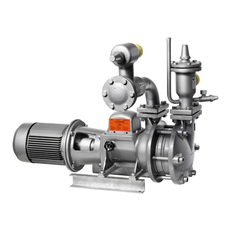
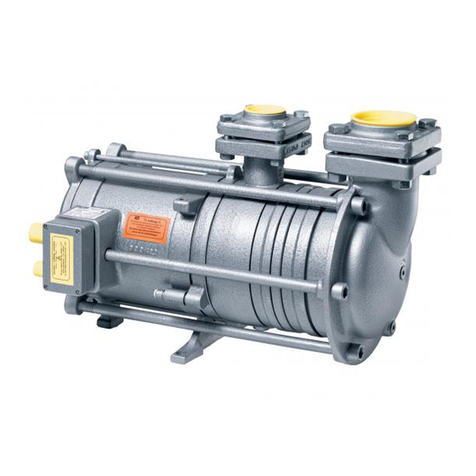
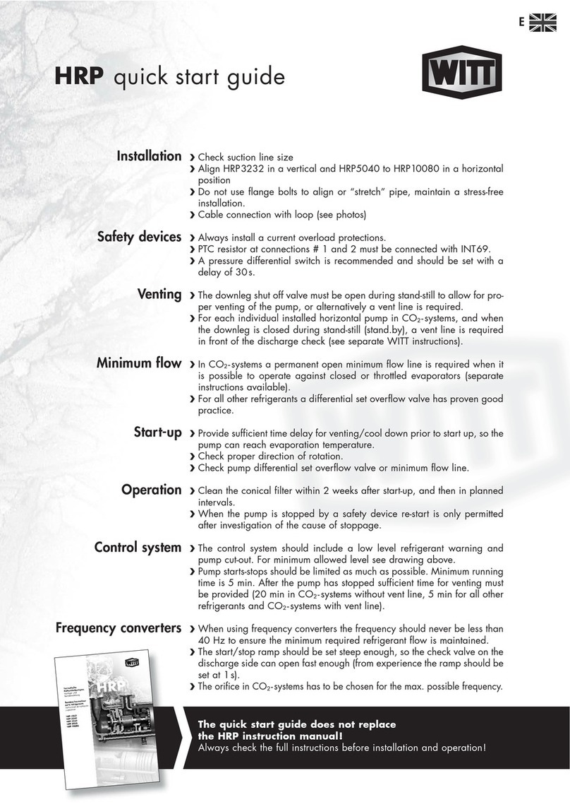
Witt HRP Series User manual


Content
1. INTRODUCTION..................................................................................................................................1
1.1 INTENDED USE.............................................................................................................................1
1.2 SAFETY REQUIREMENTS ...........................................................................................................1
1.3 SAFETY ADVICE...........................................................................................................................1
1.4 DISCLAIMER .................................................................................................................................2
2. TERMS OF WARRANTY.....................................................................................................................3
3. TECHNICAL INFORMATION ..............................................................................................................4
3.1 DESCRIPTION OF TYPES............................................................................................................4
3.2 SCOPE OF DELIVERY..................................................................................................................4
3.3 ORDER INFORMATION ................................................................................................................4
3.4 CODES / CERTIFICATES / APPROVALS.....................................................................................4
4. TECHNICAL DATA..............................................................................................................................5
4.1 GENERAL INFORMATION............................................................................................................5
4.2 ELECTRICAL DATA.......................................................................................................................5
4.3 MATERIALS ...................................................................................................................................8
4.4 PRESSURE RANGE......................................................................................................................8
4.5 DIMENSIONS.............................................................................................................................. 11
4.6 SECTIONAL VIEWS ................................................................................................................... 12
4.7 DESCRIPTION OF OPERATION ............................................................................................... 28
4.8 PERFORMANCE CHARACTERISTIC TABLE ........................................................................... 29
5. APPLICATIONS................................................................................................................................ 31
5.1 GENERAL ................................................................................................................................... 31
5.2 DETERMINATION OF THE DELIVERY HEAD .......................................................................... 32
5.3 DETERMINATION OF THE REQUIRED FLOW......................................................................... 32
5.4 ADAPTATION TO PLANT REQUIREMENTS............................................................................. 33
5.5 USE OF FREQUENCY CONVERTERS ..................................................................................... 34
6. INSTALLATION INSTRUCTIONS.................................................................................................... 35
6.1 PUMP ARRANGEMENT............................................................................................................. 35
6.2 PUMP CONNECTION................................................................................................................. 35
6.3 DOWNLEG DESIGN ................................................................................................................... 37
6.4 PUMP DISCHARGE LINE .......................................................................................................... 38
6.5 PROTECTION OF THE PUMP ................................................................................................... 39
6.6 ELECTRICAL INFORMATION.................................................................................................... 44
7. TRANSPORT AND STORAGE ........................................................................................................ 49
8. INSTALLATION AND APPLICATION.............................................................................................. 50
8.1 PREPARING THE PUMP FOR INSTALLATION ........................................................................ 50
8.2 MOUNTING INSTRUCTIONS..................................................................................................... 50

8.3 PRIOR TO COMMISSIONING.................................................................................................... 53
8.4 COMMISSIONING PROCEDURE .............................................................................................. 53
8.5 DURING NORMAL OPERATION ............................................................................................... 53
8.6 PUMP STANDSTILL (STAND-BY) ............................................................................................. 54
9. SERVICE AND MAINTENANCE ...................................................................................................... 55
9.1 REMOVING A PUMP .................................................................................................................. 55
9.2 SHIPPING OF THE PUMP ......................................................................................................... 55
9.3 GENERAL ADVICE..................................................................................................................... 55
9.4 REPARING A PUMP................................................................................................................... 56
9.5 WARNINGS................................................................................................................................. 56
10. TROUBLE SHOOTING ................................................................................................................ 58
TH. WITT Kältemaschinenfabrik GmbH
Lukasstrasse 32, D-52070 Aachen
Tel. +49-241-18208-0
https://www.th-witt.com, sales@th-witt.com
Status of documentation: October 2018
1
1. INTRODUCTION
Please read the entire manual careful before selecting, installing, commissioning and
servicing the pump.
1.1 INTENDED USE
The WITT hermetic refrigerant pump type is designed to deliver exclusively refrigerant liquid
at its boiling point.
The pump is labelled with model and design limitation for pressure and temperature.
The HRP refrigerant pump is designed with safety features, which ensures security from the
escape of ammonia; in the event the stator can leaking the pump body and the complete motor
housing is designed to 25 bar pressure to contain high pressure refrigerant will not escape
from the pump or through the electric cable connections.
Performance data of the pump are to be found in chapter 4 Technical data.
1.2 SAFETY REQUIREMENTS
All of the following specified work must be carried out by knowledgeable personnel
experienced in installation and service of refrigeration systems. All personnel must
be familiar with the national legal requirements and safety regulations. All safety
regulations and codes of practice concerning the use of refrigerants must be adhered
to, with special attention paid to protection clothing and wearing of safety glasses.
Service and maintenance should only be carried out when the pump is stopped and
the power supply disconnected.
Under no circumstances are the indicated temperature- and pressure limitations to
be exceeded.
Important! The content of this manual must be adhered to. Deviation from the
specified conditions will make any claim for liability or warrenty void.
1.3 SAFETY ADVICE
The pump is designed for use in industrial refrigeration systems of primary refrigerant.
Refrigerant is used to cool motor and bearings. Any gas that forms in the pump is discharged
to the pressure side. The electrical power consumption of the pump is low in relation to the
refrigeration capacity, due to the effect of the latent heat of the liquid being utilised.
It is very important that everybody responsible for the safe operation and
maintenance of the plant reads this manual.
I you have any problems please do not hesitate to call our service department, our staff will be
glad to assist you.

2
Avoid any tripping obstacle at ground levels, e.g. cable. If you cannot avoid such obstacles
they should be marked with two-coloured warning tape (warning sign).
Retighten all screw connections after maintenance and repair work!
If you have to disassemble any safety devices for maintenance and repair make sure that upon
completion of said work the re-assembly and proper functioning is checked!
When operating at low temperatures (< 0°C) freeze bites can occur when the surface is
touched. Therefore always wear appropriate protection clothing.
1.4 DISCLAIMER
Even when using the pump for the intended purpose it cannot be entirely excluded that a dan-
ger remains for the life of the user. Translations are carried out to the best of our knowledge.
We are unable to accept any liability for translation errors.
We reserve the right to change descriptions, graphs or other statements.
3
2. TERMS OF WARRANTY
In order to avoid accidents and ensure optimum performance, no modifications or conversions
may be carried out to the refrigerant pump without the explicit written approval by TH. WITT
KÄLTEMASCHINENFABRIK GMBH.
These instructions are based on internationally standardised SI units of measurements.
All data and information on the operation and maintenance of the refrigerant pump is provided
based on our extensive experience and to the best of our technical knowledge.
Our liability or warranty is excluded, if:
·information and instructions in the operating manual are ignored,
·the refrigerant pump including accessories is operated incorrectly or is installed contrary to
these installation instructions
·the refrigerant pump is used for applications other than that for which it was intended,
·safety devices are not used or disconnected
·there have been modifications made without written approval
·the safety regulations are not adhered to
·the refrigerant pump including its filters and required safety devices has not been main-
tained or repaired correctly with respect to frequency or competence this includes the use
of approved spare parts.
Opening the pump within the warranty period will void all implied or explicit
guarantees!
Always return the pump to the supplier for repair or order an exchange pump.
When exchanging any parts respective spare parts only genuine spare parts are to be used.
Statements in this manual shall also apply to any service fluids.

4
3. TECHNICAL INFORMATION
3.1 DESCRIPTION OF TYPES
Five hermetic pump types are available: HRP3232, HRP5040, HRP 5050, HRP8050 and
HRP10080.
"HRP" means "Hermetic Radial Pump" The numbers give the inlet and outlet pipe connection
size in DN; the first two/three digits give the size of the suction connection while the last two
digits give the size of the discharge connection.
3.2 SCOPE OF DELIVERY
·All HRP pumps, model GF, are complete with canned motor, conical strainer and coun-
ter flanges
·for HRP 3232 an additional oil drain valve type EA 10 GÜ/GB (PN 40) is included
Optional Equipment
·2 x EA: with stop valves on suction side and discharge side; discharge side with vent
valve (pressure gauge connection) and socket for flow switch /differential pressure
switch
·EA + ERA: with suction valve and discharge valve/nonreturn valve, incl. vent valve
(pressure gauge connection) and socket for flow switch /differential pressure switch
·PTC motor control INT 69 V
·oil drain valve type EA 10 GÜ/GB (PN 40)
3.3 ORDER INFORMATION
Please specify the following data when ordering a pump:
·refrigerant
·type HRP 3232, HRP 5040, HRP 505, HRP 8050 or HRP 10080
·Model, e.g. GF ,2 x EA or EA +ERA
·Voltage and frequency.
·(Special requirements if applicable, e.g. PN 65 for HRP 3232)
If you are unsure about the selection, please provide the following additional information:
·evaporating temperature ....°C
·volume flow .... m3/h or capacity and re-circulation rate
·required pressure head …. m
3.4 CODES / CERTIFICATES / APPROVALS
The following certifications are available and can be downloaded from our website www.th-
witt.com:
declaration of incorporation of a partly completed machinery according to EG machinery di-
rective, conformity declaration according to EU- low voltage directive.
5
4. TECHNICAL DATA
4.1 GENERAL INFORMATION
4.2 ELECTRICAL DATA
50 Hz 3 x 400 V
DESCRIPTION
Unit
HRP
HRP
HRP
HRP
HRP
3232
5040
5050
8050
10080
Speed
n
[min-1]
2900
2900
2900
2900
2900
max. power consumption
with NH3
Imax
[A]
1,5
4,7
5,5
7,0
13,0
with CO2
Imax
[A]
2,1
-
7,0
10,0
16,0
With HFC, HFO, e.g.
R134a
Imax
[A]
2,2
5,2
8,5
16,0**
20,0
Motor power factor
with
NH3
Cos
j
[-]
0,61
0,63
0,68
0,80
0,79
with
CO2
Cos
j
[-]
0,83
-
0,80
0,88
0,85
With HFC, HFO, e.g.
R134a
Cos
j
[-]
0,84
0,63
0,85
0,85**
0,89
Effective motor power
N
[kW]
N
wirk
= √ 3 x (U x I
wirk
x cos j)
(values at operating point –see selection tool)
DESCRIPTION
Unit
HRP
3232
HRP
5040
HRP
5050
HRP
8050**
HRP
10080
Volume refrigerant
side
ltr.
1,1
2,8
5
5,5
6,35
Volume transformer
oil
ltr.
0,75
1
1,5
1,5
1,6
Weight pump with
kg
43
55
83
83/110**
117
counterflanges
Sound pressure level
dB(A)
< 70
< 70
< 70
< 70
< 70
Class of terminal box
insulation
IP
54
54
54
54
54
Box cable sockets
prepared to
PG
1 x M16;
1 x M20
1 x M16
1 x M20
1 x M16
1 x M20;
1 x M16
1xM20/M25
**
1 x M16
1 x M25

6
60 Hz 3 x 460 V
DESCRIPTION
Unit
HRP
HRP
HRP
HRP
HRP
3232
5040
5050
8050
10080
Speed
n
[min-1]
3500
3500
3500
3500
3500
max. power consumption
with NH3
Imax
[A]
2,0
6,2
7,3
10,0
16,0
with CO2
Imax
[A]
2,6
-
9,5
16,0
24,0
With HFC, HFO, e.g.
R134a
Imax
[A]
2,9
6,9
11,5
23,5**
28,0
Motor power factor
with NH
3
Cos
j
[-]
0,88
0,86
0,87
0,90
0,90
with CO
2
Cos
j
[-]
0,92
-
0,90
0,90
0,93
With HFC, HFO, e.g.
R134a
Cos
j
[-]
0,93
0,86
0,91
0,85**
0,93
Effective motor power
N
[kW]
N
wirk
= √ 3 x (U x I
wirk
x cos j)
(values at operating point –see selection tool)
* Measure the maximum current during commissioning and set the overload protection to this
value, do not exceed Imax for the relevant refrigerant.
** Model HRP8050 requires for HFCs and HFO, e.g. R134a a special motor with the dimensions and data from
HRP10080
7
FURTHER 60 HZ MOTORS
60 Hz 3 x 380 V
DESCRIPTION
Unit
HRP
HRP
HRP
HRP
HRP
3232
5040
5050
8050
10080
Speed
n
[min-1]
3500
3500
3500
3500
3500
max. power consumption
with NH3
Imax
[A]
2,5
7,5
8,5
12
20
with CO2
Imax
[A]
3,3
-
12
18,5
30
With HFC, HFO, e.g.
R134a
Imax
[A]
3,5
8,5
13,5
24,5**
33
Motor power factor
with NH3
Cos j
[-]
0,88
0,86
0,87
0,90
0,90
with CO2
Cos j
[-]
0,92
-
0,90
0,90
0,93
With HFC, HFO, e.g.
R134a
Cos
j
[-]
0,93
0,86
0,91
0,85**
0,93
Effective motor power
N
[kW]
N
wirk
= √ 3 x (U x I
wirk
x cos j)
(values at operating point –see selection tool)
60 Hz 3 x 575 V
DESCRIPTION
Unit
HRP
HRP
HRP
HRP
HRP
3232
5040
5050
8050
10080
Speed
n
[min-1]
3500
3500
3500
3500
-
max. power consumption
with NH3
Imax
[A]
1,7
4,7
5,5
8
-
with CO2
Imax
[A]
2,2
-
8
12
-
With HFC, HFO, e.g.
R134a
Imax
[A]
2,3
5,5
9
-
-
Motor power factor
with NH3
Cos j
[-]
0,88
0,86
0,87
0,90
-
with CO2
Cos j
[-]
0,92
-
0,90
0,90
-
With HFC, HFO, e.g.
R134a
Cos
j
[-]
0,93
0,86
0,91
-
-
Effective motor power
N
[kW]
N
wirk
= √ 3 x (U x I
wirk
x cos j)
(values at operating point –see selection tool)

8
4.3 MATERIALS
Pump housing: EN-GJS-400-18-LT
Stator: steel / copper
Rotor: steel/aluminium
Bearings: PTFE
Shaft: C 35+C
Motor can: 1.4301
Impellers: GX22CrNi17M
Main bolts: 8.8
Counter flanges: P355NL1 or C22.8
Bolts for counter flanges: 8.8
Gaskets soft gasket asbestos free
Transformer oil Fuchs Renolin Eltec
Painting system: W 9.1 + W 9.2
W 9.1 + W 9.2 = 2 k epoxy finish according to DIN ISO 12944/5, RAL 7001
4.4 PRESSURE RANGE
25 bar
models
40 bar
models
65 bar
models
Design pressure
(inside pump housing, motor can and sta-
tor housing)
25
40
65
Test pressure (with oil) [bar]
60
6
0
98
Allowable pressure range
[bar]
25 (+50 / -10°C)
18,75 (-10 / -60°C)
40 (+50 / -10°C)
30 (-10 / -60°C)
65 (+50 / -10°C)
48,75 (-10 / -60°C)
For pressure testing with oil FUCHS Reniso
Synth 68 is used.
9
The following table gives an overview of available standard and special pump types. Futher
pump types are under development.
Nenndruck und verfügbare Pumpen / Design pressure and available pumps
Frequency
Design
Press.
Refrigerant
pump type
[Hz]
[bar]
50 / 60
25
NH
3
, CO
2
,
R22
HRP3232
HRP5040
HRP5050
HRP8050
HRP10080
50 / 60
25
40
Other HFC,
HFO
Standard
Standard
Standard
Standard
Standard
NH
3
, CO
2
,
R22
Special
40
Other HFC,
HFO
Not
available
Standard
Special
65
All refrigerants
Not
available
Not
available
Not
available
90
Only CO2
Not
available
Standard

10
4.5 DIMENSIONS
Fig. 1 HRP 3232
11
HRP
5040
5050
8050
10080
L
540
520
555
725
B
260
310
310
355
H
283
349
351
362
a1
150
180
180
180
a2
228
234
255
302
a3
196
170
170
290
b1
105
133
133
133
b2
154
174
174
222
c
53
53
66
70
d1
60,3
60,3
88,9
114,3
d2
48,3
60,3
60,3
88,9
l1
155
155
178
212
m1
115
145
145
145
m2
168
204
206
217
m3
130
190
190
190
HRP
5040
5050
8050
10080
f1
249
249
340
467
f2
241
249
243
---
f3
270
284
284
473
h1
115
115
155
176
h2
105
115
115
179
Fig. 2 HRP 5040/5050/8050/10080

12
4.6 SECTIONAL VIEWS
Fig. 3 a HRP 3232
13
Fig. 3b HRP5040/HRP 5050/HRP 8050/HRP 10080

14
Parts list HRP 3232 and HRP 5040
HRP 3232
HRP 5040
part
Dimension Code - No. Weight Dimension Code - No. Weight
No.
[g] [g]
suction casing
01
DN 32
2162.000336
5960
DN 50
2162.000018
5380
suction intermediate piece
2
Ø150
2162.000309
1080
Ø150
2162.000026
1087
guide vane-intermediate piece 1
3
---
---
Ø150
2162.000030
1775
discharge intermediate piece
3
Ø150
2162.000311
1240
---
---
return intermediate piece
4
---
---
Ø150
2162.000036
2037
guide vane-intermediate piece 2
5
---
---
Ø150
2162.000031
1862
discharge casing
6
DN32
2162.000307
4020
DN40
2162.000022
2540
bearing casing
7
---
---
Ø150
A7
2080
stator casing
8
Ø150
A8
6660
Ø150
A8
8260
motor cover
9
Ø150
2162.000303
2720
Ø150
2162.000010
2980
can complete (parts 11-13)
10
Ø80
A10
1660
Ø80
A10
1740
bearing cover
14
Ø79
A10
541
Ø79
A10
497
socket head cap screw
21
M6 x 25
A10
7
M6 x 25
A10
7
socket head cap screw
22
M8 x 185
5112.BH61F4
74
M8 x 275
5112.BH61HM
109
hexagon head cap screw
24a
M16 x 55
5111.AHA1BI
107
M12 x 55
5111.AH81BI
60
hexagon nut
24b
M16
5151.AHA100
30
M12
5151.AH8100
15
hexagon head cap screw
25a
---
---
M12 x 55
5111.AH81BI
60
hexagon nut
25b
---
---
M12
5151.AH8100
15
torx screw for conn. box
26
4x30 TX20
5143.CLGAAT
3
4x30 TX20
5143.CLGAAT
3
earthing screw
27
M4 x 10
5112.AO31A9
1
M4 x 10
5112.AO31A9
1
long socket head cap screw
28
M16x280
5112.BHA2HR
454
M16x450
5112.BHA3MH
730
set screw
29
---
---
M6 x 10
A7
1
Gasket suction flange
31
51/65x1
5631.254I10
3
55/77x1
5632.1BIC4I
4
Gasket discharge flange
32
51/65x2
5631.254K10
5
40/60 x2
5632.1B3BNK
6
gasket casing + intermediate
pieces
33
138/149x0,3
E30 2
138/149x0,3
E30 2
Gasket can end
34
50/58x0,3
E30
1
50/58x0,3
E30
1
gasket motor cover
35
24/54x0,5
E30
1
30/40x0,5
E30
1
O-ring EA10 GÜ/GB
37
11x2,5
5642.ABAV01
1
---
---
---
metall gasket for 1/4" screw plug
38
14/20x1,5
E30
3
14/20x1,5
E30
3
set screw protection
39
---
---
Ø 5x5
A7
1
bearing sleeve
41
40/50x20
E41
110
40/50x20
E41
110
bearing bush
42
26/52x23
E41
132
26/52x23
E41
132
bearing strip
43
20/119x1
E42
5
20/119x1
E42
5
retaining disc
44
38,5/52x1
E42
2
38,5/52x1
E42
2
bearing disc
45
35/50x5
2162.000082
38
35/50x5
A7
38
key
46
5 x 7,5
5712.AGF001
4
5 x 7,5
5712.AGF001
4
radial impeller 1
47
Ø 111
2162.000313
175
Ø 111
2162.000040
300
radial impeller 2
48
---
---
Ø 111
2162.000041
273
circlip ring
49
---
---
Ø 18
5541.AAH120
1
temperature switch
50
---
---
70 °C
2162.000071
25
PTC resistor
50
90 °C
A8
25
90 °C
A8
25
transformer oil
51
1 Ltr
9832.100001
1425
1,0 Ltr
9832.100001
1425
stator
52
Ø 139
A8
4980
Ø 139
A8
9340
cable insulating plastic tube
54
A8
1
A8
1
cable protective tube
55
A8
1
A8
1
supporting sleeve
56
Ø 80 x 45
2162.000053
154
Ø 80 x 45
2162.000053
154
Supporting sleeve safety
57
2162.000085
6
2162.000085
6
screw plug 1/4"
58
5116.OG6210
13
5116.OG6210
13
cable inlet nipple
59
A8
27
A8
27
shaft
61
A60
---------
A60
------
rotor
62
Ø 80
A60
3970
Ø 80
A60
3720
balancing disc
64
A60
260
A60
260
connecting box, compl.
71
98/64/38
2162.000075
243
98/64/38
2162.000075
243
15
backup fuse for PTC resistor
71a
2591.000101
1
2591.000101
1
sensor wire
77a
---
---
A7
1
sensor wire insulation
77b
---
---
A7
1
sensor connecting cover
78
---
---
A7
15
sensor inlet nipple
79
---
---
A7
27
counterflange suction side
83
DN32
E21
1720
DN50
E21
1194
counterflange discharge side
84
DN32
E22
1720
DN40
E22
713
threaded bar
86a
M12x180
5122.BFAJEZ
127
M12x180
5122.BFAJEZ
127
hexagon nut
86b
M12
5151.AH8100
15
M12
5151.AH8100
15
limpet washer
86c
Ø30/13x3
5161.K11100
12
Ø30/13x3
5161.K11100
12
suction strainer
91
Ø50x125
2196.000002
13
Ø50x125
2196.000002
13
bearing filter
92
---
---
Ø57x57
2162.000084
54
ejector
93
---
---
A7
80

16
HRP replacement assemblies and spare part sets
HRP3232
HRP5040
Part
Article No.
Weight [g]
Part
Article No.
Weight [g]
bearing casing with parts:
A7
2162.A00092
2162.A00090
HRP 3232: 6;41; 45; E30; E42; 51;
4938
HRP 5040
: 7;41;
45; E30; E42; 51, 77-79;
29; 39; 93
2330
stator with parts:
A8
2162.A00116
2162.A00114
HRP 3232: 08;52;54;55;59;71;E30;E42;51
6360
HRP5040:
08;50;52;54;55;59;71;E30;E42;51
17650
motor can with parts:
A10
2162.A00053
3161
2162.A00051
2354
10;41;14;21; E30; E42; 51
Balanced shaft, rotor+impellers:
---
A60
2162.A00010
6453
61-64; 42; 46; 47, 48, 49; E30; E42; 51
shaft with rotor with parts:
A61
2162.A00118
2162.A00112
HRP 3232: 61-64; 42; 46; E30; E42; 51
5460
HRP 5040: 61-64; 42; 46; 49; E30; E42; 51
5880
counterfl. suct. incl. mount.mat.
E21
2162.000500
2212
E21
2162.000145
1600
4x 24a, 4x 24b, 2x31, 83
counterfl. Deliv. incl. mount.mat
E22
2162.000500
2212
E22
2162.000144
967
4x 25a, 4x25b, 1x32, 84
set of gaskets: number x no.
E30
2162.000170
2162.000124
HRP 3232: 6x33, 1x34, 2x38
28
HRP 5040:
2x31; 1x32; 9x33 ; 1x34; 1x35;
4x38
37
bearing sleeve (41) + -bush (42)
E41
2162.000126
241
2162.000126
241
bearing
strips (2x43) +
retaining discs (2x44)
E42
2162.000127
7
2162.000127
7
17
Parts list HRP5050
HRP 5050
HRP 5050 CO
2
part
dimension
code -
no.
Weight [g]
dimension
code -
no.
Weight [g]
suction casing
1
DN 50
2162.001002
7440
DN 50
2162.001002
7440
suction intermediate piece
2
Ø196
2162.001004
2420
Ø196
2162.001004
2420
guide vane-interm. piece 1
3
Ø196
2162.001007
3100
Ø196
2162.001013
3100
return intermediate piece
4
Ø196
2162.001006
5040
Ø196
2162.001006
5040
guide vane-interm. piece 2
5
Ø196
2162.001008
3470
Ø196
2162.001008
3470
guide plate for interm. piece 2
5a
2162.002041
126
2162.002041
126
..Screw for guide plate
5b
M6 x 10
5112.BC51A9
5
M6 x 10
5112.BC51A9
5
discharge casing
6
DN 50
2162.000024
4080
DN 50
2162.000024
4080
bearing casing
7
Ø196
A7
2880
Ø196
A7- CO2
2880
stator casing
8
Ø196
A8
10550
Ø196
A8- CO2
10550
motor cover
9
Ø196
2162.000012
3640
Ø196
2162.000012
3640
can compl. (incl. parts 11-13)
10
Ø95
A10
3055
Ø95
A10- CO2
3055
bearing cover
14
Ø79
A10
497
Ø79
A10- CO2
497
socket head cap screw
21
M6 x 25
A10
7
M6 x 25
A10- CO2
7
socket head cap screw
22
M8 x 245
5112.BH61GS
98
M8 x 245
5112.BH61GS
98
hexagon head cap screw
24a
M16 x 65
5111.AH81BI
126
M16 x 65
5111.AH81BI
126
hexagon nut
24b
M16
5151AH8100
30
M16
5151AH8100
30
hexagon head cap screw
25a
M12 x 55
5111.AH81BI
60
M12 x 55
5111.AH81BI
60
hexagon nut
25b
M12
5151.AH8100
15
M12
5151.AH8100
15
torx screw for conn. box
26
4x30 TX20
5143.CLGAAT
3
4x30 TX20
5143.CLGAAT
3
earthing screw
27
M4 x 10
5112.AO31A9
1
M4 x 10
5112.AO31A9
1
long socket head cap screw
28
M16x450
5112.BHA3MH
730
M16x450
5112.BHA3MH
730
set screw
29
M6 x 10
A7
1
M6 x 10
A7- CO2
1
joint suction flange
31
55/77x2
5632.1BIC4I
4
55/77x2
5632.1BIC4I
4
joint discharge flange
32
55/77x2
5632.1BIC4K
8
55/77x2
5632.1BIC4K
8
joint casing + interm. pieces
33
180/195x0,3
E30
3
180/195x0,3
E30
3
joint can end
34
50/58x0,3
E30
1
50/58x0,3
E30
1
joint motor cover
35
30/40x0,5
E30
1
30/40x0,5
E30
1
joint 1/4" screw plug
38
14/20x1,5
E30
3
14/20x1,5
E30
3
set screw protection
39
Ø 5x5
A7
1
Ø 5x5
A7- CO2
1
bearing sleeve (motor side)
41
40/50x20
E41.1
108
40/50x20
E41.1 - CO2
108
bearing sleeve II (pump side9
41.1
40/60x20
E41.1
147
---
---
---
bearing sleeve III (pump side)
41.1-
CO2
--- --- --- 40/70x20
E41.1 - CO2
147
bearing bush II (pump side)
42.1
26/60x28
E41.1
237
---
---
---
bearing bush II.3 (pump
side)
42.1-
CO2
--- --- --- 26/60x28
E41.1 - CO2
218
bearing bush I.2 (motor side)
42.2
26/52x23
E41.1
124
26/52x23
E41.1 - CO2
124
bearing strip
43
20/119x1
E42.1
5
20/119x1
E42.1- CO2
5
retaining disc (motor side)
44
38,5/52x1
E42.1
2
38,5/52x1
E42.1- CO2
2
retaining disc II (pump side)
44.1
39,5/60x1
E42.1
4
---
---
---
retaining disc IV (pump side)
44.1-
CO2
--- --- --- 41,5/70x3
E42.1- CO2
6
bearing disc
45
35/50x5
A7
38
35/50x5
A7- CO2
38
key
46
6 x 10
5712.AHH001
9
6 x 10
5712.AHH001
9
radial impeller 1
47
Ø 136
2162.001009
475
Ø 136
2162.001011
475
radial impeller 2
48
Ø 136
2162.001010
460
Ø 136
2162.001012
460
circlip ring
49
Ø 26
5541.AAP120
2
---
---
---
PTC resistor wire outlet
50
90 °C
A8
25
90 °C
A8- CO2
25
transformer oil, 2 L required
51
1,0 L
9832.100001
1425
1,0 L
9832.100001
1425
stator
52
Ø 180
A8
15000
Ø 180
A8- CO2
15000
cable insulating plastic tube
54
A8
1
A8- CO2
1
cable protective tube
55
A8
1
A8- CO2
1
supporting sleeve
56
Ø101,6 x 47
2162.000054
298
Ø101,6 x 47
2162.000054
298
supporting sleeve safety
57
2162.000085
6
2162.000085
6
screw plug 1/4"
58
5116.OG6210
13
5116.OG6210
13
cable inlet nipple
59
A8
27
A8- CO2
27
shaft
61
A60
---
A60- CO2
---
rotor
62
Ø 95
A60
---
Ø 95
A60- CO2
---
balancing disc
64
A60
---
A60- CO2
---

18
connecting box, compl.
71
98/64/38
2162.000075
243
98/64/38
2162.000075
243
backup fuse for PTC resistor
71a
2591.000101
1
2591.000101
1
sensor wire
77a
A7
1
A7- CO2
1
sensor wire insulation
77b
A7
1
A7- CO2
1
sensor connecting cover
78
A7
15
A7- CO2
15
sensor inlet nipple
79
A7
27
A7- CO2
27
counterflange suction side
83
DN50
E21
1194
DN50
E21
1194
counterflange discharge side
84
DN50
E22
1194
DN50
E22
1194
threaded bar
86a
M12x180
5122.BFAJEZ
127
M12x180
5122.BFAJEZ
127
hexagon nut
86b
M12
5151.AH8100
15
M12
5151.AH8100
15
limpet washer
86c
Ø30/13x3
5161.K11100
12
Ø30/13x3
5161.K11100
12
Conical filter, suction side
91
Ø50x125
2196.000002
13
Ø50x125
2196.000002
13
bearing filter
92
Ø57x57
2162.000084
54
Ø57x57
2162.000213
54
ejector
93
A7
80
A7- CO2
80
complete HRP-replacement assemblies and spare part sets
HRP 5050
HRP 5050 CO
2
Teil
Artikelnummer
Gewicht [g]
Artikelnummer
Gewicht [g]
bearing casing and shaft with rotor
U1
2162.A00093
12000
--- ---
---
A7 + A60
until 3/2003
stator with parts:
A8
2162.A00117
25520
--- ---
---
08, 50, 51, 52, 54, 55, 59, 71, E30, E42
Motor can with parts:
A10
2162.A00050
3670 --- ---
--
10, 14, 21, 41, 51, E30, E42
bearing sleeve + bearing bush, parts:
E41
2162.000126
241 ---- ---
---
2x41 +2x42
Bearing strip + retaining disks:
E42
2162.000127
7 --- ---
---
2x43 + 2x44
bearing casing with parts:
A7
2162.A00088
3200 --- ---
---
07, 29, 39, 41.1, 45, 51, 77
-
79, 93,
E30, E42.1
since 04/03
stator with parts
A8
2162.A00120
25520
--- ---
---
08, 50, 51, 52, 54, 55, 59, 71, E30,
E42.1
since 04/03
Motor can with parts:
A10
2162.A00054
3670 --- ---
---
10, 14, 21, 41.1, 51, E30, E42.1
since 04/03
shaft with rotor with parts:
A61
2162.A00009
8750 --- ---
---
42, 42.1, 46; 49, 51, 61
-
64, E30, E42.1
since 04/03
Balanced shaft, rotor + impellers:
A60
2162.A00011
9685 A60- CO2
2162.A00012
9685
42.2, 42.1, 46; 47, 48, 49, 51, 61-64,
E30, E42.1
s
ince 01/10
bearing sleeve + bearing bush
E41.1
2162.000200
241
E41.1
CO2
2162.000230
241
1x41.1 + 1x41 + 1x42.1 + 1x42.2
since 04/03
bearing strips + retaining disks
E42.1
2162.000202
7 E42.1
2162.000202
7
2x43 + 1x44.1 + 1x44
since 04/03
bearing casing with parts:
--- --- A7 - CO2
2162.A00096
5150
19
07, 29, 39, 41.1
-CO2
, 45, 51, 77-79,
93, E30, E42.1
- CO2
since 01/12
stator with parts
--- --- A8- CO2
2162.A00124
25520
08, 50, 51, 52, 54, 55, 59, 71, E30,
E42.1
- CO2
since 01/12
Motor can
with parts:
--- --- A10- CO2
2162.A00057
3670
10, 14, 21, 41, 51, E30, E42.1
- CO2
since 01/12
bearing sleeve + bearing bush
--- --- E41.1- CO2
2162.000233
241
1x41.1
- CO2+ 1x41 + 1x42.1-
CO2+
1x42.2
since 01/12
bearing
strips + retaining disks: --- --- E42.1- CO2
2162.000232
7
2x43 + 1x44.1
-CO2+ 1x44
since 01/12
set of gaskets: number x no.
E30
2162.001200
33 E30
2162.001200
33
2x31; 1x32; 9x33 ; 1x34; 1x35; 3x38
..Counterflan
ge incl. mount. mat. E21
2162.000145
1600 E21
2162.000145
1600
4 x
24a, 4 x 24b, 2 x 31, 83
..Counterflan
ge incl. mount. mat. E22
2162.000145
1600 E22
2162.000145
1600
4 x
25a, 4 x 25b, 1 x 32, 84
Blindflange suction side
---
2162.009100
2650 ---
2162.009100
2650
Inkl. Befestigungsmaterial
Blindflange
pressure side ---
2162.009100
2650 ---
2162.009100
2650
including mounting material

20
Parts list HRP8050
HRP 8050
HRP8050 CO
2
part
dimension
code -
no.
Weight [g]
dimension
code -
no.
Weight [g]
suction casing
1
DN 80
2162.000178
9040
DN 80
2162.000178
9040
suction intermediate piece
2
Ø196
2162.000028
2276
Ø196
2162.000028
2276
guide vane-interm. piece 1
3
Ø196
2162.000033
3764
Ø196
2162.009002
3764
return intermediate piece
4
Ø196
2162.000038
3684
Ø196
2162.000038
3684
guide vane-interm. piece 2
5
Ø196
2162.000034
3854
Ø196
2162.000034
3854
guide plate for interm. piece 2
5a
2162.002041
126
2162.002041
126
..Screw for guide plate
5b
M6 x 10
5112.BC51A9
5
M6 x 10
5112.BC51A9
5
discharge casing
6
DN 50
2162.000024
4080
DN 50
2162.000024
4080
bearing casing
7
Ø196
A7
2880
Ø196
A7- CO2
2880
stator casing
8
Ø196
A8
10550
Ø196
A8- CO2
10550
motor cover
9
Ø196
2162.000012
3640
Ø196
2162.000012
3640
can compl. (incl. parts 11-13)
10
Ø95
A10
3055
Ø95
A10- CO2
3055
bearing cover
14
Ø79
A10
497
Ø79
A10- CO2
497
socket head cap screw
21
M6 x 25
A10
7
M6 x 25
A10- CO2
7
socket head cap screw
22
M8 x 245
5112.BH61GS
98
M8 x 245
5112.BH61GS
98
hexagon head cap screw
24a
M16 x 65
5111.AHA1BS
126
M16 x 65
5111.AHA1BS
126
hexagon nut
24b
M16
5151AHA100
30
M16
5151AHA100
30
hexagon head cap screw
25a
M12 x 55
5111.AH81BI
60
M12 x 55
5111.AH81BI
60
hexagon nut
25b
M12
5151.AH8100
15
M12
5151.AH8100
15
torx screw for conn. box
26
4x30 TX20
5143.CLGAAT
3
4x30 TX20
5143.CLGAAT
3
earthing screw
27
M4 x 10
5112.AO31A9
1
M4 x 10
5112.AO31A9
1
long socket head cap screw
28
M16x450
5112.BHA3MH
730
M16x450
5112.BHA3MH
730
set screw
29
M6 x 10
A7
1
M6 x 10
A7- CO2
1
joint suction flange
31
77/100 x1
5632.1C4CRI
6
77/100 x1
5632.1C4CRI
6
joint discharge flange
32
55/77x2
5632.1BIC4K
8
55/77x2
5632.1BIC4K
8
joint casing + interm. pieces
33
180/195x0,3
E30
3
180/195x0,3
E30
3
joint can end
34
50/58x0,3
E30
1
50/58x0,3
E30
1
joint motor cover
35
30/40x0,5
E30
1
30/40x0,5
E30
1
joint 1/4" screw plug
38
14/20x1,5
E30
3
14/20x1,5
E30
3
set screw protection
39
Ø 5x5
A7
1
Ø 5x5
A7- CO2
1
bearing sleeve I.2 (motor side)
41
40/50x20
E41.1
110
40/50x20
E41.1 –CO2
110
bearing sleeve II.2 (pump side)
41.1
40/60x20
E41.1
150
---
---
---
bearing sleeve III (pump side)
41.1-CO2
---
---
---
40/70x20
E41.1 –CO2
147
bearing bush II (pump side)
42.1
26/60x28
E41.1
240
---
---
---
bearing bush II.3 (pump side)
42.1-CO2
---
---
---
26/60x28
E41.1 –CO2
220
Bearing bush I.2 (motor side)
42.2
26/52x23
E41.1
125
26/52x23
E41.1 –CO2
125
bearing strip
43
20/119x1
E42.1
5
20/119x1
E42.1- CO2
5
retaining disc
44
38,5/52x1
E42.1
2
38,5/52x1
E42.1- CO2
2
retaining disc II
44.1
39,5/60x1
E42.1
4
---
---
---
retaining disc II
44.1-CO2
---
---
---
41,5/70x3
E42.1- CO2
6
bearing disc
45
35/50x5
A7
38
35/50x5
A7- CO2
38
key
46
6 x 10
5712.AHH001
9
6 x 10
5712.AHH001
9
radial impeller 1
47
Ø 136
2162.000043
557
Ø 136
2162.009000
558
radial impeller 2
48
Ø 136
2162.000044
513
Ø 136
2162.009001
514
circlip ring
49
Ø 26
5541.AAP120
2
---
---
---
PTC resistor wire outlet
50
90 °C
A8
---
90 °C
A8- CO2
---
transformer oil, (2 L required)
51
1,0 L
9832.100001
1425
1,0 L
9832.100001
1425
stator
52
Ø 180
A8
15000
Ø 180
A8- CO2
15000
cable insulating plastic tube
54
---
A8
1
---
A8- CO2
1
cable protective tube
55
---
A8
1
---
A8- CO2
1
supporting sleeve
56
Ø101,6 x 47
2162.000054
298
Ø101,6 x 47
2162.000054
298
supporting sleeve safety
57
---
2162.000085
6
---
2162.000085
6
screw plug 1/4"
58
---
5116.OG6210
13
---
5116.OG6210
13
cable inlet nipple
59
---
A8
---
---
A8- CO2
---
shaft
61
---
A60
---
---
A60 –CO2
---
rotor
62
Ø 95
A60
3700
Ø 95
A60 –CO2
3700
balancing disc
64
A60
260
A60 –CO2
260
connecting box, compl.
71
98/64/38
2162.000075
243
98/64/38
2162.000075
243
backup fuse for PTC resistor
71a
---
2591.000101
1
---
2591.000101
1
21
sensor wire
77a
---
A7
1
---
A7- CO2
1
sensor wire insulation
77b
---
A7
1
---
A7- CO2
1
sensor connecting cover
78
---
A7
15
---
A7- CO2
15
sensor inlet nipple
79
---
A7
27
---
A7- CO2
27
counterflange suction side
83
DN80
E21
1625
DN80
E21
1625
counterflange discharge side
84
DN50
E22
1194
DN50
E22
1194
threaded bar
86a
M12x180
5122.BFAJEZ
127
M12x180
5122.BFAJEZ
127
hexagon nut
86b
M12
5151.AH8100
15
M12
5151.AH8100
15
limpet washer
86c
Ø30/13x3
5161.K11100
12
Ø30/13x3
5161.K11100
12
Conical filter, suction side
91
Ø83/76x160
2196.000004
17
Ø83/76x160
2196.000004
17
bearing filter
92
Ø57x57
2162.000084
54
Ø57x57
2162.000213
54
ejector
93
---
A7
80
---
A7- CO2
80

22
complete HRP-replacement assemblies and spare part sets
HRP 8050
HRP 8050 CO
2
Teil
Artikelnummer
Gewicht [g]
Teil
Artikelnummer
Gewicht [g]
bearing casing and shaft with rotor
U1
until
03/2003
2162.A00095
12000
---
--- ---
A7 + A60
stator with parts:
A8
2162.A00115
25520
---
--- ---
08, 50, 51, 52, 54, 55, 59, 71, E30, E42
can with parts:
A10
2162.A00052
3670
---
--- --
10, 14, 21, 41, 51, E30, E42
bearing sleeve + bearing bush
E41
2162.000126
241
----
--- ---
2x41 +2x42.2
bearing strip + retaining disk
:
E42
2162.000127
7
---
--- ---
2x43 + 2x44
bearing casing with parts:
A7
since 04/03
2162.A00091
3200
---
--- ---
07, 29, 39, 41.1, 45, 51, 77
-79, 93, E30, E42.1
stator with parts
:
A8
since 04/03
2162.A00121
25520
---
--- ---
08, 50, 51, 52, 54, 55, 59, 71, E30, E42.1
can with parts:
A10
since 04/03
2162.A00056
3670
---
--- ---
10, 14, 21, 41.1, 51, E30, E42.1
shaft with rotor with parts:
A61
since 04/03
2162.A000113
7130
---
--- ---
42.
1, 42.2, 46; 49, 51, 61-64, E30, E42.1
Balanced shaft, rotor + impellers:
A60
since 01/10
2162.A00013
8200
A60
-
CO2
2162.A00014
8202
42.
1- CO2, 42.2, 46; 47, 48, 49, 51, 61-
64, E30, E42.1
bearing sleeve + bearing bush
:
E41.1
since 04/03
2162.000200
241
---
--- ---
1x41.1 + 1x41 + 1x42.1 + 1x42.2
bearing strip + retaining disk
:
E42.1
since 04/03
2162.000202
7
---
--- ---
2x43 + 1x44.1 + 1x44
bearing casing with parts:
---
since 01/12
--- ---
A7
-
CO2
2162.A00097
5150
07, 29, 39, 41.1
-CO2, 45, 51, 77-
79, 93, E30, E42.1-
CO
2
stator with parts
: ---
since 01/12
--- ---
A8
-
CO2
2162:A00125
25520
08, 50, 51, 52, 54, 55, 59, 71, E30, E42.1
- CO2
can with parts:
---
since 01/12
--- ---
A10
-
CO2
2162.A00058
3670
10, 14, 21, 41, 51, E30, E42.1
- CO2
bearing sleeve + bearing bush
:
---
since 01/12
--- ---
E41.1-CO2
2162.000233
241
1x41.1
-CO2+ 1x41 + 1x42.1-CO2+ 1x42.2
bearing strip + retaining disk
:
---
since 01/12
--- ---
E42.1-
CO2
2162.000232
7
2x43 + 1x44.1
-CO2+ 1x44
set of joints: number x no. :
E30
2162.000125
33
E30
2162.000125
33
2x31; 1x32; 9x33 ; 1x34; 1x35; 3x38
23
..Counterflan
ge incl. mount. mat.
E21
2162.000146
2531
E21
2162.000146
2531
4 x 24a, 4 x 24b, 2 x 31, 83,
..Counterflan
ge incl. mount. mat.
E22
2162
.000145
1600
E22
2162.000145
1600
4 x 25a, 4 x 25b, 1 x 32, 84
Blindflange suction side
---
2162.002210
3500
---
2162.002210
3500
Inkl. Befestigu
ngsmaterial
Blindflange pressure side
---
2162.009100
2650
---
2162.009100
2650
including mounting material

24
Parts list HRP8050-2
HRP 8050-2
part
dimension
code - no.
Weight [g]
suction casing
1
DN 80
2162.000178
9040
suction intermediate piece
2
Ø196
2162.000028
2276
guide vane-interm. piece 1
3
Ø196
2162.000033
3764
return intermediate piece
4
Ø196
2162.000038
3684
guide vane-interm. piece 2
5
Ø196
2162.000034
3854
guide plate for interm. piece 2
5a
2162.002041
126
..Screw for guide plate
5b
M6 x 10
5112.BC51A9
5
discharge casing
6
DN 50
2162.000024
4080
bearing casing
7
Ø196
A7-CO2
2880
stator casing
8
Ø196
A8
10550
motor cover
9
Ø196
2162.000012
3640
can compl. (incl. parts 11-13)
10
Ø95
A10
3055
bearing cover
14
Ø79
A10
497
socket head cap screw
21
M6 x 25
A10
7
socket head cap screw
22
M8 x 245
5112.BH61GS
98
hexagon head cap screw
24a
M16 x 65
5111.AHA1BS
126
hexagon nut
24b
M16
5151AHA100
30
hexagon head cap screw
25a
M12 x 55
5111.AH81BI
60
hexagon nut
25b
M12
5151.AH8100
15
torx screw for conn. box
26
4x30 TX20
5143.CLGAAT
3
earthing screw
27
M4 x 10
5112.AO31A9
1
long socket head cap screw
28a
M16x285
5112.BHA2HW
462
Screw adaptor
28b
M16
2162.002039
350
long socket head cap screw
28c
M16x220
5112.BHA1G3
320
set screw
29
M6 x 10
A7-CO2
1
joint suction flange
31
77/100 x1
5632.1C4CRI
6
joint discharge flange
32
55/77x2
5632.1BIC4K
8
joint casing + interm. pieces
33
180/195x0,3
E30
3
joint can end
34
50/58x0,3
E30
1
joint motor cover
35
30/40x0,5
E30
1
joint 1/4" screw plug
38
14/20x1,5
E30
3
set screw protection
39
Ø 5x5
A7-CO2
1
Bearing sleeve I.2 (motor side)
41
40/50x20
E41.1-CO2
110
bearing sleeve III (pump side)
41.1-CO2
40/70x20
E41.1-CO2
147
bearing bush II.3 (pump side)
42.1
26/60x28
E41.1-CO2
220
bearing bush I.2 (motor side)
42.2
26/52x23
E41.1-CO2
125
bearing strip
43
20/119x1
E42.1-CO2
5
retaining disc (motor side)
44
38,5/52x1
E42.1-CO2
2
retaining disc IV (pump side)
44.1-CO2
41,5/70x3
E42.1-CO2
6
bearing disc
45
35/50x5
A7-CO2
38
key
46
6 x 10
5712.AHH001
9
radial impeller 1
47
Ø 136
2162.000043
557
radial impeller 2
48
Ø 136
2162.000044
513
circlip ring
49
Ø 26
5541.AAP120
2
PTC resistor wire outlet
50
90 °C
A8
---
transformer oil, (2 L required)
51
1,0 L
9832.100001
1425
stator
52
Ø 180
A8
15000
cable insulating plastic tube
54
A8
1
cable protective tube
55
A8
1
supporting sleeve
56
Ø101,6 x 47
2162.000054
298
supporting sleeve safety
57
2162.000085
6
screw plug 1/4"
58
5116.OG6210
13
cable inlet nipple
59
A8
shaft
61
A60
---
rotor
62
Ø 95
A60
3700
balancing disc
64
A60
260
connecting box, compl.
71
98/64/38
2162.000075
243
backup fuse for PTC resistor
71a
2591.000101
1
sensor wire
77a
A7-CO2
1
sensor wire insulation
77b
A7-CO2
1
sensor connecting cover
78
A7-CO2
15
sensor inlet nipple
79
A7-CO2
27
counterflange suction side
83
DN80
E21
1625
counterflange discharge side
84
DN50
E22
1194
threaded bar
86a
M12x180
5122.BFAJEZ
127
hexagon nut
86b
M12
5151.AH8100
15
limpet washer
86c
Ø30/13x3
5161.K11100
12
Conical filter, suction side
91
Ø83/76x160
2196.000004
17
bearing filter
92
Ø57x57
2162.000084
54
ejector
93
A7-CO2
80
25
complete HRP-replacement assemblies and spare part sets
HRP 8050-2
Part
Article No. Weight [g]
bearing casing with parts:
A7-CO2
2162.A00097 5150
07, 29, 39, 41.1, 45, 51, 77
-
79, 93, E30,
E42.1
stator with parts
:
A8
2162.A00127 25520
08, 50, 51, 52, 54, 55, 59, 71, E30, E42.1
can with parts:
A10
2162.A00060 3670
10, 14, 21, 41.1, 51, E30, E42.1
Balanced shaft, rotor
+ impellers:
A60
2162.A00019 7830
42.1, 42.2, 46; 47, 48
, 49, 51, 61-
64, E30,
E42.1
bearing sleeve + bearing bush
:
E41.1
-
CO2
2162.000233 241
1x41.1 + 1x41 + 1x42.1 + 1x42.2
bearing strip + retaining disk
:
E42.1
-
CO2
2162.000232 7
2x43 + 1x44.1 + 1x44
set of joints: number x no. :
E30
2162.000125 33
2x31; 1x32; 9x33 ; 1x34; 1x35; 3x38
Counterflan
ge incl. mount. mat.
E21
2162.000146 2531
..4 x 24a, 4 x 24b, 2 x 31, 83,
Counterflan
ge incl. mount. mat.
E22
2162.000145 1600
4 x 25a, 4 x 25b, 1 x 32, 84
Blindflange suction side
---
2162.002210 3500
including mounting material
Blindflange pressure side
---
2162.009100 2650
including mounting material

26
Parts list HRP10080
HRP 10080
HRP10080 CO
2
part
dimension
code - no.
Weight [g]
dimension
code - no.
Weight [g]
suction casing
1
DN 100
2162.002011
11420
DN 100
2162.002011
11420
suction intermediate piece
2
Ø196
2162.002015
2160
Ø196
2162.002015
2160
guide vane-interm. piece 1
3
Ø196
2162.002017
4760
Ø196
2162.002059
4760
return intermediate piece
4
Ø196
2162.002020
3940
Ø196
2162.002020
3940
guide vane-interm. piece 2
5
Ø196
2162.002018
3040
Ø196
2162.002018
3040
guide plate for interm. piece 2
5a
2162.002041
126
2162.002041
126
..Screw for guide plate
5b
M6 x 10
5112.BC51A9
5
M6 x 10
5112.BC51A9
5
discharge casing
6
DN 80
2162.002013
5720
DN 80
2162.002013
5720
bearing casing
7
Ø196
A7
2880
Ø196
A7- CO2
2880
stator casing
8
Ø196
A8
18000
Ø196
A8- CO2
10550
motor cover
9
Ø196
2162.000012
3640
Ø196
2162.000012
3640
can compl. (incl. parts 11-13)
10
Ø95
A10
3645
Ø95
A10- CO2
3645
bearing cover
14
Ø79
A10
497
Ø79
A10- CO2
497
socket head cap screw
21
M6 x 25
A10
7
M6 x 25
A10- CO2
7
socket head cap screw
22
M8 x 365
5112.BH61K4
143
M8 x 365
5112.BH61K4
143
hexagon head cap screw
24a
M16 x 55
5111.AHA1BI
110
M16 x 55
5111.AHA1BI
110
hexagon nut
24b
M16
5151.AHA100
30
M16
5151.AHA100
30
hexagon head cap screw
25a
M 16 x 70
5111.AHA1BX
135
M 16 x 70
5111.AHA1BX
135
hexagon nut
25b
M16
5151.AHA100
30
M16
5151.AHA100
30
torx screw for conn. box
26
4x30 TX20
5143.CLGAAT
3
4x30 TX20
5143.CLGAAT
3
earthing screw
27
M4 x 10
5112.AO31A9
1
M4 x 10
5112.AO31A9
1
long socket head cap screw
28a
M16x285
5112.BHA2HW
462
M16x285
5112.BHA2HW
463
long socket head cap screw
28b
M16
5112.002039
350
M16
5112.002039
350
set screw
29
M6 x 10
A7
1
M6 x 10
A7- CO2
1
joint suction flange
31
96/119x1
5632.1CNDAI
7
96/119x1
5632.1CNDAI
7
joint discharge flange
32
77/100x2
5632.1C4CRK
12
77/100x2
5632.1C4CRK
12
joint casing + interm. pieces
33
180/195x0,3
E30
3
180/195x0,3
E30
3
joint can end
34
50/58x0,3
E30
1
50/58x0,3
E30
1
joint motor cover
35
30/40x0,5
E30
1
30/40x0,5
E30
1
joint 1/4" screw plug
38
14/20x1,5
E30
3
14/20x1,5
E30
3
set screw protection
39
Ø 5x5
A7
1
Ø 5x5
A7- CO2
1
bearing sleeve I.2 (motor side)
41
40/50x20
E41.1
110
40/50x20
E41.1 –CO2
110
bearing sleeve II.2 (pump side)
41.1
40/60x20
E41.1
150
---
---
---
bearing sleeve III (pump side)
41.1-CO2
---
---
---
40/70x20
E41.1 –CO2
147
bearing bush II (pump side)
42.1
26/60x28
E41.1
240
---
---
---
bearing bush II.3 (pump side)
42.1- CO2
---
---
---
26/60x28
E41.1 –CO2
220
bearing bush I.2 (motor side)
42.2
26/52x23
E41.1
125
26/52x23
E41.1 –CO2
125
bearing strip
43
20/119x1
E42.1
5
20/119x1
E42.1- CO2
5
retaining disc (motor side)
44
38,5/52x1
E42.1
2
38,5/52x1
E42.1- CO2
2
retaining disc II (pump side)
44.1
39,5/60x1
E42.1
4
---
---
---
retaining disc IV (pump side)
44.1-CO2
---
---
---
41,5/70x3
E42.1- CO2
6
bearing disc
45
35/50x5
A7
38
35/50x5
A7- CO2
38
key
46
6 x 10
5712.AHH001
9
6 x 10
5712.AHH001
9
radial impeller 1
47
Ø 136
A60
660
Ø 136
A60 –CO2
660
radial impeller 2
48
Ø 136
A60
520
Ø 136
A60 –CO2
520
circlip ring
49
Ø 26
5541.AAP120
2
---
---
---
PTC resistor wire outlet
50
90 °C
A8
---
90 °C
A8- CO2
---
transformer oil, 2 L required
51
1,0 L
9832.100001
1425
1,0 L
9832.100001
1425
stator
52
Ø 180
A8
---
Ø 180
A8- CO2
---
cable insulating plastic tube
54
---
A8
1
---
A8- CO2
1
cable protective tube
55
---
A8
1
---
A8- CO2
1
supporting sleeve
56
Ø101,6 x 47
2162.000054
298
Ø101,6 x 47
2162.000054
298
supporting sleeve safety
57
---
2162.000085
6
---
2162.000085
6
screw plug 1/4"
58
---
5116.OG6210
13
---
5116.OG6210
13
cable inlet nipple
59
---
A8
---
A8- CO2
---
shaft
61
---
A60
---
---
A60 –CO2
---
rotor
62
Ø 95
A60
8300
Ø 95
A60 –CO2
8300
balancing disc
64
---
A60
260
A60 –CO2
260
connecting box, compl.
71
98/98/82
2162.002036
670
98/98/82
2162.002036
670
backup fuse for PTC resistor
71a
---
2591.000101
1
---
2591.000101
1
sensor wire
77a
---
A7
1
---
A7- CO2
1
sensor wire insulation
77b
---
A7
1
---
A7- CO2
1
sensor connecting cover
78
---
A7
15
---
A7- CO2
15
sensor inlet nipple
79
---
A7
27
---
A7- CO2
27
counterflange suction side
83
DN 100
E21
2320
DN 100
E21
2320
counterflange discharge side
84
DN 80
E22
1625
DN 80
E22
1625
threaded bar
86a
M12x180
5122.BFAJEZ
127
M12x180
5122.BFAJEZ
127
hexagon nut
86b
M12
5151.AH8100
15
M12
5151.AH8100
15
limpet washer
86c
Ø30/13x3
5161.K11100
12
Ø30/13x3
5161.K11100
12
Conical filter, suction side
91
Ø100x160
2196.000005
35
Ø100x160
2196.000005
35
bearing filter
92
Ø57x57
2162.000084
54
Ø57x57
2162.000213
54
ejector
93
A7
141
---
A7- CO2
141
27
complete HRP-replacement assemblies and spare part sets
HRP 10080
HRP 10080 CO
2
Part
Arti
cle No.
Weigh
t [g]
Arti
cle No.r
Weight [g]
bearing casing with parts:
A7
2162.A00089
3200 --- --- ---
07, 29, 39, 41.1, 45, 51, 77
-
79, 93, E30,
E42.1
stator with parts:
A8
2162.A02032
25520 --- --- ---
08, 50, 51, 52, 54, 55, 59, 71, E30, E42.1
can with parts:
A10
2162.A02007
3670 --- --- ---
10, 14, 21, 41.1, 51, E30, E42.1
balanced shaft, rotor + impellers:
A60
since 01/10
2162.A00015
12588 --- --- ---
42.
1, 42.2, 46; 47, 48, 49, 51, 61-
64, E30,
E42.1
bearing sleeve + bearing bush:
E41.1
2162.000200
241 --- --- ---
1x41.1 + 1x41 + 1x42.1 + 1x42.2
bearing strip + retaining disk:
E42.1
2162.000202
7 --- --- ---
2x43 + 1x44.1 + 1x44
bearing casing with parts:
---
since 01/12
--- --- A7- CO2
2162.A00098
5170
07, 29, 39, 41
.1-CO2, 45, 51, 77-
79, 93,
E30, E42.1-CO2
stator with parts:
---
since 01/12
--- --- A8- CO2
2162.A00126
25520
08, 50, 51, 52, 54, 55, 59, 71, E30, E42.1
can with parts:
---
since 01/12
--- --- A10- CO2
2162.A00059
3670
10, 14, 21, 41.1, 51, E30, E42.1
balanced shaft, rotor + impellers:
---
since 01/12
--- --- A60-CO2
2162.A00018
12570
3, 42.1, 42.2, 46; 47, 48, 49, 51, 61-64,
E30, E42.1- CO2
balanced shaft, rotor + impellers:
---
until 12/11
--- --- A62- CO2
2162.A00017
7810
42.1, 42.2, 46; 47, 48, 49, 51, 61
-
64, E30,
E42.1-CO2
bearing sleeve + bearing bush:
---
since 01/12
--- --- E41.1- CO2
2162.000233
241
1x41.1
-CO2+ 1x41 + 1x42.1-
CO
2
+
1x42.2
bearing strip + retaining disk:
---
ab 01/2012
--- --- E42.1- CO2
2162.000232
7
2x43 + 1x44.1-CO2+ 1x44
set of joints: number x no. :
E30
2162.002037
33 E30
2162.002037
33
2x31; 1x32; 9x33 ; 1x34; 1x35; 3x38
..counterflange incl. mount. mat.
E21
2162.002038
3535 E21
2162.002038
3535
4 x 24a, 4 x 24b, 2 x 31, 83,
..counterflange incl. mount. mat.
E22
2162.000146
2531 E22
2162.000146
2531
4 x 25a, 4 x 25b, 1 x 32, 84

28
4.7 DESCRIPTION OF OPERATION
From the surge drum refrigerant liquid flows into the suction chamber of the pump. In the suction
connection a conical screen is placed. A special design of the suction chamber reduces the inlet
friction. The pressure is increased in two stages through impellers and intermediate pieces. A
built in ejector is designed to provide adequate cooling of bearings and motor.
By the differential pressure in the pump some of the liquid refrigerant is bled to the back bearings
through the hollow shaft. On top of each intermediate piece there is a small bypass hole connect-
ing the suction and discharge side. When gas has collected in the discharge chamber it can vent
through these holes to the suction chamber and from there returning to the surge drum. It is
important that the downleg must be designed in such a way that the pump venting can take place
(see chapter 6).
For the HRP 3232 the design of a vertical motor shaft allows the free flow of any gas bubbles that
may form.
Pumps with horizontal motor shaft (HRP 5040, HRP 5050, HRP 8050 and HRP 10080) are
equipped with a sensor behind the bearing filter to detect wear of the bearings. While the pump
is at stand still at connection (position 77) on the out-side of the pump you can measure the
electrical resistance through the shaft. If there is a short circuit, i.e. down to earth, the bearings
are worn and the pump should be sent in for repair.
Transformer oil is used in the stator housing between the motor can and the outside casing. This
oil is useful to prevent moisture entering the stator, conducts the motor heat away to the outside
casing.
A thermistor is integrated in the stator windings to sense any abnormal rise in temperature and
interrupt the motor supply.
29
4.8 PERFORMANCE CHARACTERISTIC TABLE
60 Hz, 3 x 460V
Druckdifferenz "p [bar]
Volumenstrom V[m³/h]
Pressure difference "p [bar]
Volume flow V[m³/h]
R717
R22, R134a
R507
CO
2
HRP
3232
HRP
5040
HRP
5050
HRP
8050
HRP
10080
Delivery
head
at evaporation temperature t
0
H [m]
0°C
-40°C
0°C
-40°C
0°C
-40°C
0°C
-40°C
2
0,13
0,14
0,25
0,28
0,23
0,25
0,18
0,22
5,2
13,9
16,4
35
66,1
4
0,25
0,27
0,50
0,55
0,45
0,51
0,36
0,44
5,2
13,8
16,3
35
66,0
6
0,38
0,41
0,75
0,83
0,68
0,76
0,55
0,66
5,1
13,6
16,2
35
65,6
8
0,50
0,54
1,00
1,10
0,91
1,02
0,73
0,88
5,0
13.4
16,0
35
64,8
10
0,63
0,68
1,26
1,38
1,14
1,27
0,91
1,09
4,8
13,3
15,9
35
63,7
15
0,94
1,02
1,88
2,07
1,70
1,91
1,37
1,64
4,7
12.8
15,4
34,8
60,8
20
1,25
1,35
2,51
2,76
2,27
2,54
1,82
2,19
4,4
12,1
14,9
32,8
57,9
25
1,57
1,69
3,14
3,45
2,84
3,18
2,28
2,74
4,1
11,2
14,3
30,7
54.8
30
1,88
2,03
3,77
4,14
3,41
3,82
2,73
3,28
3,6
10,1
13,7
28,5
51,3
35
2,19
2,37
4,40
4,83
3,97
4,45
3,19
3,83
3,0
8,8
13,1
26,6
47,7
40
2,51
2,71
5,02
5,52
4,54
5,09
3,64
4,38
2,2
7,3
12,3
24,7
44,0
45
2,82
3,05
5,65
6,21
5,11
5,72
4,10
4,93
1,1
5,7
11.5
22,9
39,7
50
3,13
3,39
6,28
6,90
5,68
6,36
4,55
5,47
-
3,6
10,5
20,7
34,1
55
3,45
3,72
6,91
7,59
6,24
7,00
5,01
6,02
-
-
9,4
18,3
28,5
60
3,76
4,06
7,53
8,28
6,81
7,63
5,46
6,57
-
-
7,9
15,7
23,0
65
4,07
4,40
8,16
8,97
7,38
8,27
5,92
7,11
-
-
6,0
13,0
14,0
70
4,39
4,74
8,79
9,66
7,95
8,90
6,37
7,66
-
-
2,6
9,7
-
75
4,70
5,08
9,42
10,35
8,52
9,54
6,83
8,21
-
-
-
-
-
Table 1
50 Hz, 3 x 400V
Druckdifferenz "p [bar]
Volumenstrom V[m³/h]
Pressure difference "p [bar]
Volume flow V[m³/h]
R717
R22, R134a
R507
CO
2
HRP
3232
HRP
5040
HRP
5050
HRP
8050
HRP
10080
Delivery
head
at evaporation temperature t
0
H [m]
0°C
-40°C
0°C
-40°C
0°C
-40°C
0°C
-40°C
2
0,13
0,14
0,25
0,28
0,23
0,25
0,18
0,22
5,6
13,2
15
30,0
55,0
4
0,25
0,27
0,50
0,55
0,45
0,51
0,36
0,44
5,0
13,0
14,6
29,9
53,7
6
0,38
0,41
0,75
0,83
0,68
0,76
0,55
0,66
4,7
12,6
14,4
29,4
53,0
8
0,50
0,54
1,00
1,10
0,91
1,02
0,73
0,88
4,4
12,0
14,2
28,7
52,5
10
0,63
0,68
1,26
1,38
1,14
1,27
0,91
1,09
4,2
10,5
13,9
28,0
52,1
15
0,94
1,02
1,88
2,07
1,70
1,91
1,37
1,64
3,6
9,0
13,2
26,1
50,3
20
1,25
1,35
2,51
2,76
2,27
2,54
1,82
2,19
3,0
8,0
12,3
24,2
46,8
25
1,57
1,69
3,14
3,45
2,84
3,18
2,28
2,74
2,3
5,2
11,5
22,4
42,6
30
1,88
2,03
3,77
4,14
3,41
3,82
2,73
3,28
-
1,5
10,4
20,1
37,9
35
2,19
2,37
4,40
4,83
3,97
4,45
3,19
3,83
-
-
9,1
18,2
32,7
40
2,51
2,71
5,02
5,52
4,54
5,09
3,64
4,38
-
-
7,5
15,0
26,6
45
2,82
3,05
5,65
6,21
5,11
5,72
4,10
4,93
-
-
5,2
12,5
20,4
50
3,13
3,39
6,28
6,90
5,68
6,36
4,55
5,47
-
-
2,0
9,1
10,9
55
3,45
3,72
6,91
7,59
6,24
7,00
5,01
6,02
-
-
-
-
-
60
3,76
4,06
7,53
8,28
6,81
7,63
5,46
6,57
-
-
-
-
-
65
4,07
4,40
8,16
8,97
7,38
8,27
5,92
7,11
-
-
-
-
-
70
4,39
4,74
8,79
9,66
7,95
8,90
6,37
7,66
-
-
-
-
-
75
4,70
5,08
9,42
10,35
8,52
9,54
6,83
8,21
-
-
-
-
-

30
In CO2-systems with minimum flow line the given volume flow is not fully available for the system.
A part of the pump volume flow will be by-passed via minimum flow line back into the vessel.
31
5. APPLICATIONS
5.1 GENERAL
In industrial refrigeration systems pumps are used to deliver refrigerant to the evaporators.
WITT hermetic refrigerant pumps are designed especially for this purpose. The principle of a
pump re-circulation system is shown in fig. 4.
Fig. 4 principle of pump re-circulation system
WITT HRP refrigerant pumps differ from conventional centrifugal pump designs due to the fact
that large volumes of entrained vapour (gas bubbles) do not completely stop delivery of the
refrigerant liquid.
Large volumes of gas occur in the pump suction when the evaporation temperature of the plant
varies during the production cycle, particularly when starting the compressor (pull-down) and
during the rapid loading or unloading of compressor steps of capacity.
Large amounts of gas bubbles in the pump suction line will cause the mass flow of liquid re-
frigerant to be reduced.
Special attention has to be taken to ensure that the pump suction lines are generously sized.
It is important hermetic pumps are supplied with liquid refrigerant at all times. Long
periods of cavita
-
tion must be avoided, as this will cause premature failure of the
pump. It is important the installation instructions in chapter. 6 are correctly
understood and followed.
When a minimum flow into the system can be guaranteed at all times, no by-pass lines are
required (see chapter 6)
OPERATIONAL LIMITATIONS
All HRP pumps are suitable for use at 50/60 Hz and all common refrigerants, e.g. NH3, CO2,
R134a, R404a, R410, R507, etc.

32
HRP8050 requires, when operated with synthetic refrigerants (HFC, HFO), e.g.
R134a, R404A, R410, R507, a larger motor. Therefore these re
-
frigerants must be
specified w
hen ordering!
A horizontal separator is recommended: this gives greater surface area for the settlement of
any oil and stable
suction head conditions.
5.2 DETERMINATION OF THE DELIVERY HEAD
The required delivery head is the resistance the pump needs to overcome to supply the evap-
orator with the high-est pressure loss with sufficient liquid refrigerant (in most cases this will
be the furthest distant evaporator).
The delivery head is depending from:
·Height difference between pumps and evaporators
·Resistance of pipe work and evaporators
·Pressure losses of valves and fittings in the delivery line
·Density of the refrigerant
The max. allowable delivery head should never be exceeded, because otherwise the pump is
operated outside the permitted range and will see internal damages (see chap. 6.5)
5.3 DETERMINATION OF THE REQUIRED FLOW
The evaporators have to be supplied with sufficient liquid refrigerant, so that
·The surface of the evaporators is fully used
·Supply to several evaporators with ifferent duties is as even as possible.
The re-circulation rate is calculated as follows:
Re − circulation rate = mass flow pump
evaporated refrigerant = !pump
!Q0
A re-circulation factor of 4 means that 3 parts refrigerant are returned as liquid and 1 part is
evaporated.
The re-circulation rate depends on the type of evaporator equipment and operation conditions.
The larger the duty, loading rate, the greater the recommended re-circulation factor.
33
RE-CIRCULATION RATES AND PUMP CAPACITY
Recirculation factor
Recirculation
flow in m³/hr
per 100 kW*
Refrigerant
CO2
NH3
R22
CO2
NH3
R22
Air Cooler
1,2 –2,0
3 - 4
2 - 3
1,4 –2,4
1,3 –1,8
2,8 –4,3
Plate Freezer
5 - 10
7 - 10
5 - 10
6 - 12
3 –4,5
6,5 - 13
Liquid Chiller
1,2 –1,5
1,2 –1,5
1,2 –1,5
1,4 –1,6
0,6
1,7
*) including re-circulation rate
Table 2
5.4 ADAPTATION TO PLANT REQUIREMENTS
Fig. 5 shows different plant operating conditions. The delivery head H is shown in relation to
the required plant capacity Q.
Performance curve characteristics of the refrigerant pump are shown in fig 5A. The different
points W mark the varying plant conditions that may occur during operation.
If the required liquid flow does not correspond with the available pump capacity then the liquid
flow to the sys-tem can be adjusted as follows:
pump capacity too large:
·
switch off a pump
·
open a liquid bypass valve, fig. 5B
·speed control of the pump, fig 5C
pump capacity too small:
·
switch on an extra pump, fig 5D
·
install a larger pump
Fig. 5, A-D
V1 +V2 # 2 x V1

34
5.5 USE OF FREQUENCY CONVERTERS
When using frequency converters the frequency should never be less than 40 Hz to ensure
the minimum required refrigerant flow is maintained.
The start/stop ramp should be set steep enough, so the check valve on the discharge valve
can open fast enough. (From experience the ramp should be set at 1 s).
Since a differential set overflow valve cannot be used for the varying pressure differences over
the pump, it must be ensured in a different way that there is always sufficient flow through the
pump.
If operating against closed evaporators is possible, a permanent open bypass line is required.
Further information regarding recommended control systems can be found in the annex at the
end.
35
6. INSTALLATION INSTRUCTIONS
To ensure trouble free operation some basic rules need to be applied to the installation
of the HRP pumps.
6.1 PUMP ARRANGEMENT
The installation must be designed as compact as possible below the separator or
low-pressure receiver. Allow sufficient access space around the pumps for removing
or replacing the pump, servicing valves, setting pressure difference control,
inspection and cleaning the conical strainer. Also allow space for normal frost/ice
accumulation around the pump.
Vertical distance between bottom of the separator to the pump centre shall be at
least 1 m. Greater distance will make the pump less sensitive to system pressure
fluctuations.
Particularly with CO2 applications of temperatures warmer than –10°C a
minimum suction head of 1,5 m is required!
The downleg should be positioned in such a way that gas entrainment from the return line is
minimised (e.g. installation of the return line with an elbow in a safe distance).
The suspended mounting of the pumps with threaded bars of at least 180 mm length
is recommended. HRP 5040, HRP5050, HRP8050 and HRP10080 should be
aligned horizontally, wheres the HRP 3232.
Please consider that
·A condensate trip tray can easily be placed and cleaned.
·The conical suction line filter can be cleaned easily.
·Stress in the piping system is avoided.
6.2 PUMP CONNECTION
The top connection of the suction line to the separator can be made with a down pipe with
vortex breaker.
The vortext breaker shall consist of crossed plates with a baffle plate on top to avoid any vor-
texing. Vortex breakers are available from TH. WITT.
Above the baffle plate of the vortex breaker there should be at least 15mm refrigerant level (in
CO2systems a minimum coverage of 50mm is required).
When using non-soluble oils in ammonia systems special attention must be
taken
that any oil, which may settle, does not drain into the duty or stand
-by
pump.
Therefore it is recommended that the suction down leg protrudes into the surge drum by 30 -
40 mm, depending on the vessel diameter (see fig. 6a).
Other manuals for HRP Series
2
This manual suits for next models
5
Table of contents
Other Witt Water Pump manuals
Popular Water Pump manuals by other brands

Ampco Pumps Company
Ampco Pumps Company ZP3 Series Installation and maintenance manual

BIANCO PUMPZ
BIANCO PUMPZ LSC530 installation manual

Eaton
Eaton 26 Series Repair Information

Eaton
Eaton 70142 Repair Information

SMC Networks
SMC Networks ZB Series Operation manual

Greenlee
Greenlee Fairmont H4665A Service manual

Hozelock Cyprio
Hozelock Cyprio Aquaforce 6000 Instruction booklet

BUSCH
BUSCH R5 RU 0050 B instruction manual

Kipor
Kipor KGP15H Operation manual

Wayne
Wayne 320802-001 Operating instructions and replacement parts list

LEYBOLD
LEYBOLD SOGEVAC SV 16 Original operating instructions

ekwb
ekwb EK-Quantum Kinetic TBE D5 PWM installation manual