Wittenstein Alpha INIRA ZST 200-334-1000-R1 C-35 User manual

2022-D050733 Revision: 02
INIRA®
Assembly instructions

INIRA®
2022-D050733 Revision: 02
WITTENSTEIN alpha GmbH
Walter-Wittenstein-Straße 1
D-97999 Igersheim
Germany
Utility film
https://alpha.wittenstein.de/rack-assembly/
Customer Service department
[email protected] +81-3-6680-2835
Türkiye WITTENSTEIN Güç Aktarma
© WITTENSTEIN alpha GmbH 2018
Subject to technical and content changes without notice.

INIRA®
Revision: 02 2022-D050733 en-1
Table of Contents
1 About this manual ................................................................................................2
1.1 Information symbols and cross references ..........................................................2
1.2 Scope of delivery .................................................................................................2
2 Safety.....................................................................................................................2
2.1 EC/EU Directive ...................................................................................................3
2.1.1 Machinery Directive.........................................................................................3
2.2 Personnel.............................................................................................................3
2.3 Intended use ........................................................................................................3
2.4 Reasonably foreseeable misuse..........................................................................3
2.5 General safety instructions ..................................................................................3
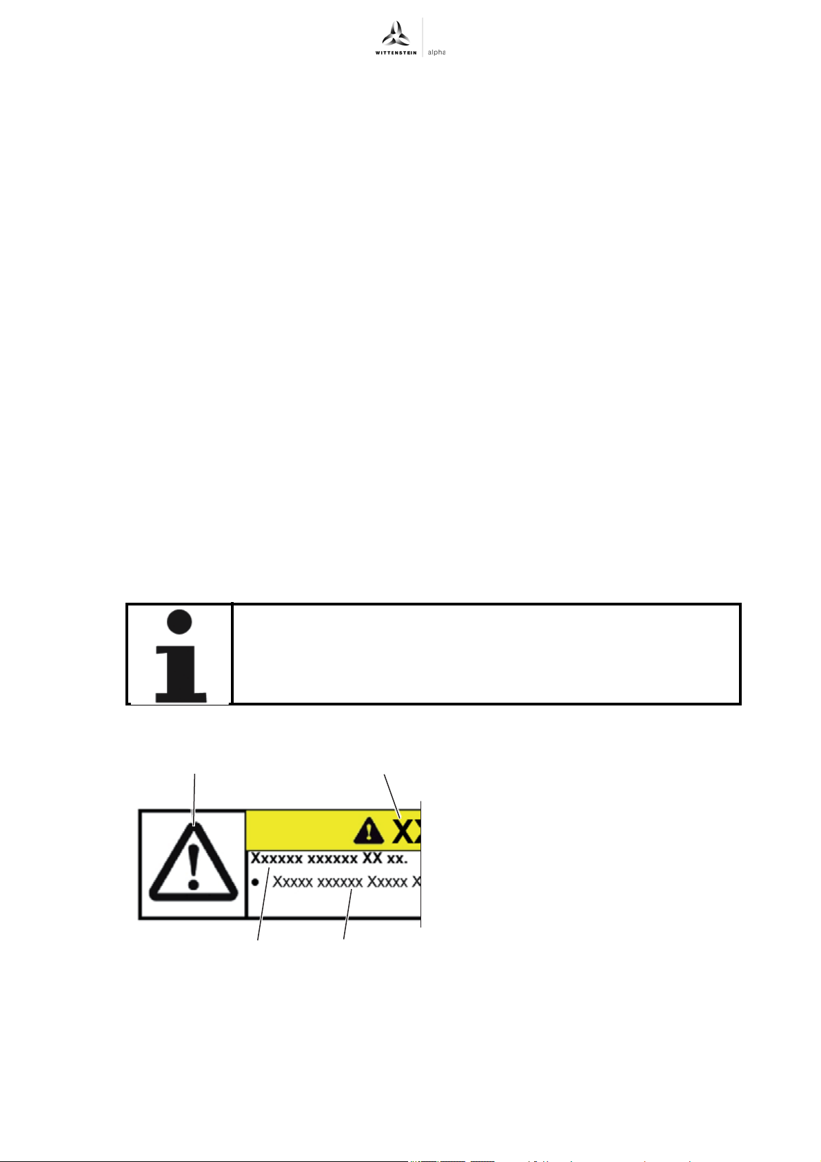
2.6 Structure of warning instructions..........................................................................3
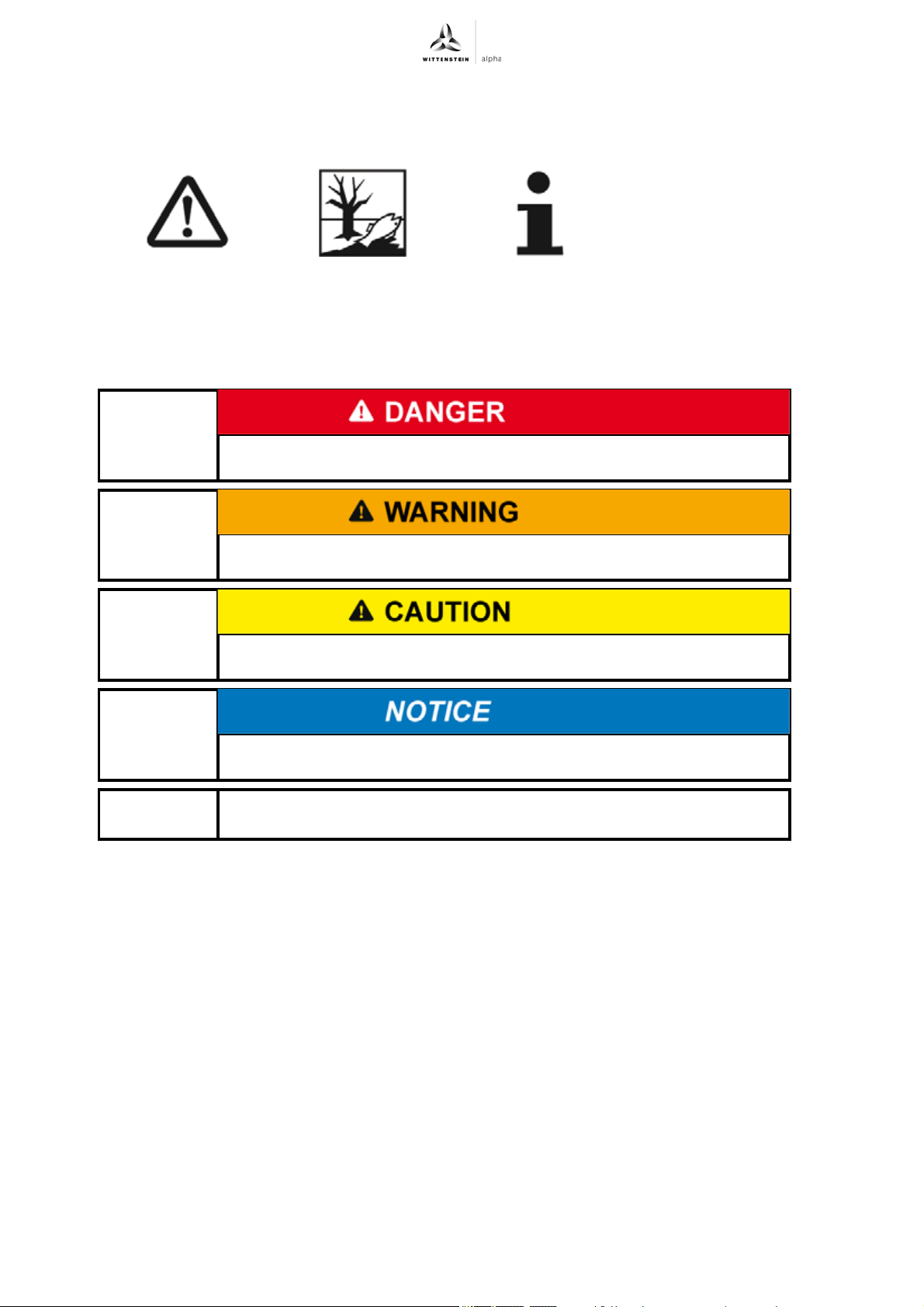
2.6.1 Safety symbols ................................................................................................4
2.6.2 Signal words....................................................................................................4
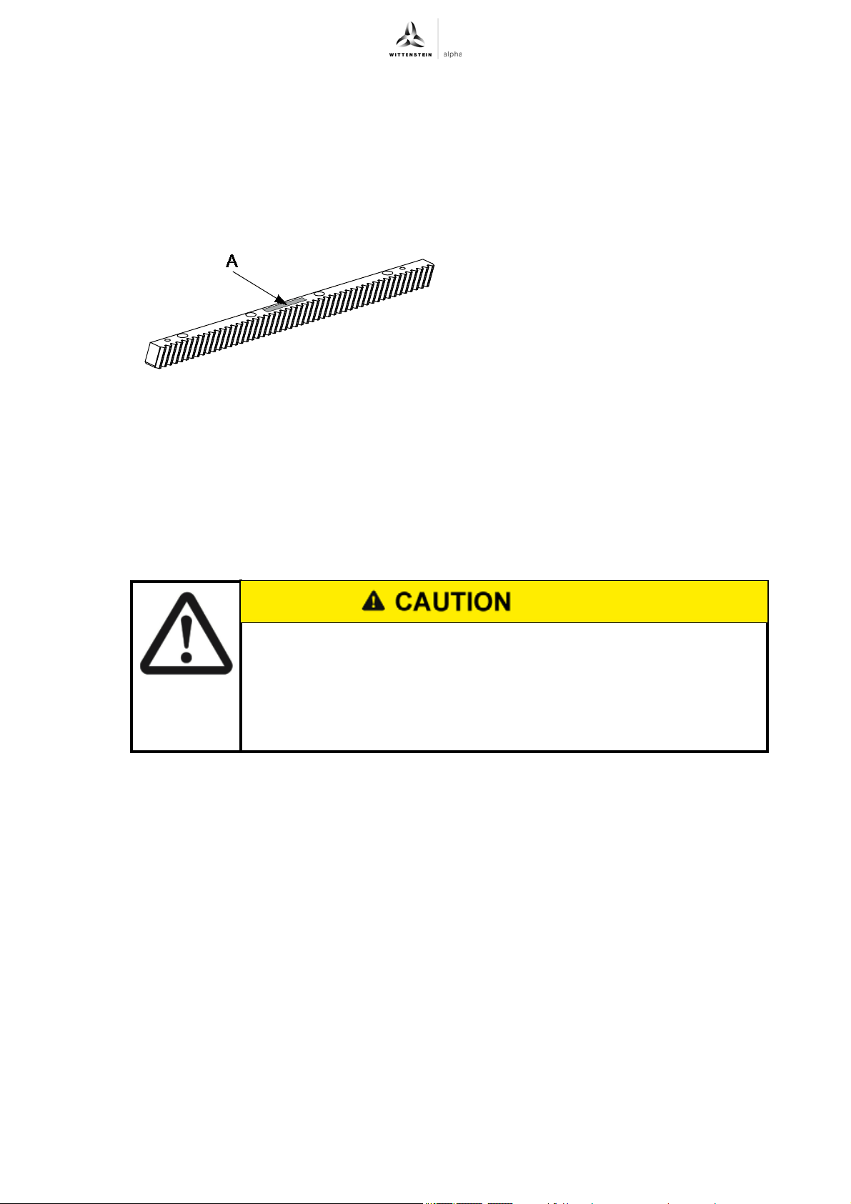
3 Description of racks.............................................................................................5
3.1 Ordering code / Name plate.................................................................................5
4 Transport and storage .........................................................................................5
4.1 Packaging ............................................................................................................5
4.2 Transport..............................................................................................................5
4.3 Storage ................................................................................................................5
5 Assembly ..............................................................................................................6
5.1 Requirements in respect of installation location and mounting base ...................6
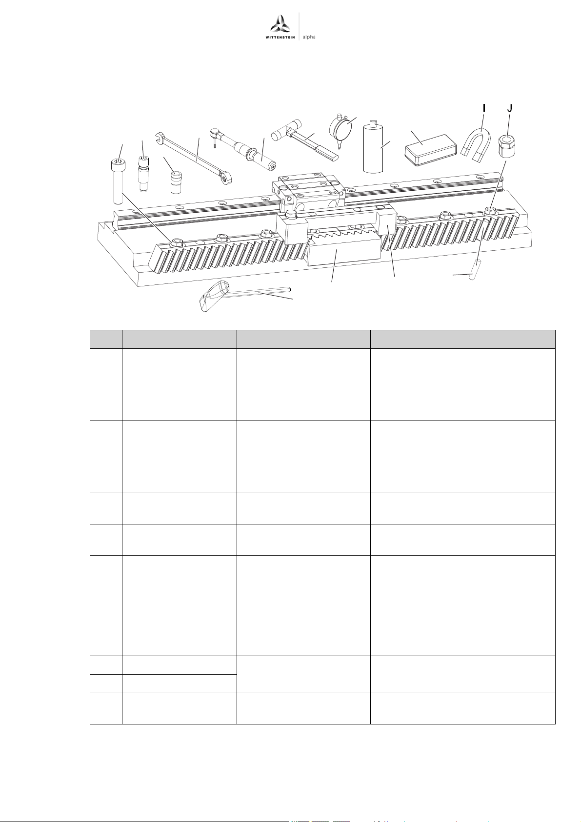
5.2 Required tools and assembly material.................................................................7
5.3 Preparations.........................................................................................................8
5.3.1 After the cleaning ............................................................................................9
5.4 Mounting the racks.............................................................................................10
5.4.1 Assemble first rack with INIRA clamping.......................................................10
5.4.2 Assembling subsequent racks.......................................................................11
5.4.3 Checking the transition between the racks....................................................12
5.4.4 Correct the transition between the racks with INIRA adjusting .....................13
5.4.5 Mounting additional racks..............................................................................14
5.5 Checking the parallelism of all racks..................................................................14
5.6 Pinning the racks ...............................................................................................14
5.6.1 Pinning the racks (conventional) ...................................................................14
5.6.2 Pinning the racks with INIRA pinning ............................................................14
6 Startup and operation ........................................................................................16
7 Maintenance and disposal.................................................................................17
7.1 Disassembly / replacement................................................................................17
7.2 Disposal .............................................................................................................17
8 Malfunctions .......................................................................................................17
9 Appendix .............................................................................................................18
9.1 Weight of racks ..................................................................................................18
9.2 Information for mounting the racks ....................................................................18
9.2.1 Overview of the required fastening screws ...................................................18
9.2.2 Overview of the mounting kit MKP (mounting pin) ........................................18
9.2.3 Overview of tool sizes ...................................................................................19
9.2.4 Tightening torques for assembly bushings....................................................19
9.3 Specifications for mounting onto a mounting base ............................................19
9.4 Maximum height of the stop surface on the machine bed .................................19
9.5 Permissible parallelism deviation of the assembly surface................................20
9.6 Permissible roll size fluctuation at the rack transition ........................................20
9.7 Permissible roll size fluctuation within an axis ...................................................20
9.8 Overview of the assembly accessory kit ............................................................21
9.9 Tightening torques for common thread sizes in general
mechanical engineering .....................................................................................21

About this manual INIRA®
en-2 2022-D050733 Revision: 02
1 About this manual
This operating manual contains necessary information to safely and correctly install the racks.
The operator must ensure that this operating manual is read by all persons assigned to install,
operate, or maintain the drive system, and that they fully comprehend its content.
In addition, the basic instructions for the "alpha rack and pinion system" (doc. no 2022-D001333),
which contain additional important safety information, must also be read.
Store this manual within reach of the drive system.
Inform colleagues who work in the area around the machine about the safety and warning notices
to avoid injuries.
The original instructions were prepared in German; all other language versions are translations of
these instructions.
1.1 Information symbols and cross references
The following information symbols are used:
Indicates an action to be performed
Indicates the results of an action
Provides additional information about the action
A cross reference refers to the chapter number and the header of the target section (e. g. 2.3
"Intended use").
A cross reference on a table refers to the table number (e. g. Table "Tbl-15").
1.2 Scope of delivery
Check the completeness of the delivery against the delivery note.
Missing parts or damage must be notified immediately in writing to the carrier, the
insurance company, or WITTENSTEIN alpha GmbH.
2 Safety
These instructions, especially the safety and warning notices as well as the rules and regulations
valid for the operating site, must be observed by all persons working with the racks.
The following, especially, must be strictly adhered to:
Observe the instructions for transport and storage.
Apply the racks exclusively in accordance with their intended use.
Carry out maintenance and repair work appropriately and professionally in conformity with the
specified intervals.
Always mount, dismantle, and operate the racks properly
(e.g. also test run only with lubrication).
Operate the racks only with lubrication (type and amount).
Prevent soiling of the racks.
Only carry out modifications or reconstructions when these are approved in writing by the
WITTENSTEIN alpha GmbH.
Personal injuries or material damage, or other claims arising from non-observance of these
minimum requirements, are the sole responsibility of the operator.
In addition to the safety-related information in this manual, also observe any legal and otherwise
applicable rules and regulations, particularly for accident prevention (e.g. personal safety
equipment) and environmental protection.

INIRA®Safety
Revision: 02 2022-D050733 en-3
2.1 EC/EU Directive
2.1.1 Machinery Directive
The racks are considered a "machine component" and are therefore not subject to the EC
Machinery Directive 2006/42/EC.
Startup is prohibited within the area of validity of the EC directive until it has been determined that
the machine in which these racks are installed corresponds to the regulations within this directive.
2.2 Personnel
Only technicians who have read and understood this operating manual may perform work on the
racks. Based on their training and experience, technicians must be able to evaluate the tasks
assigned to them in order to recognize and avoid risks.
2.3 Intended use
Racks are used to convert rotational motion to linear motion or vice versa and are intended to be
installed in a machine.
To avoid danger to the operator or damage to the machine, employ the racks only for their
intended use and in a technically flawless and safe state.
If you notice any altered operating behavior, check the racks in accordance with Chapter 8
"Malfunctions".
Read the general safety instructions before beginning to work (see Chapter 2.5 "General
safety instructions").
2.4 Reasonably foreseeable misuse
All applications other than the intended use specified, are deemed to be improper use and are
therefore prohibited.
2.5 General safety instructions
2.6 Structure of warning instructions
The general safety instructions are contained in the basic operating
manual "alpha rack and pinion system" (doc. no. 2022-D001333).
Ignoring the safety instructions can lead to severe injuries or to
damage to the racks and/or the machine in which these are fitted.
Warning instructions are situation-specific. They
will be precisely where tasks are described in
which dangers can arise.
The warning instructions in this manual are
designed according to the following pattern:
A = Safety symbol
(see Chapter 2.6.1 "Safety symbols")
B = Signal word (see Chapter 2.6.2 "Signal words")
C = Type and consequence of the danger
D = Avoiding the danger
AB
CD

Safety INIRA®
en-4 2022-D050733 Revision: 02
2.6.1 Safety symbols
The following safety symbols are used to indicate possible hazards, prohibitions, and important
information:
2.6.2 Signal words
The following signal words are used to indicate possible hazards, prohibitions, and important
information:
General hazard Environmental
protection
Information
This signal word indicates an imminent danger that will cause serious
injuries or even death.
This signal word indicates a potential hazard that could cause serious
injuries and even death.
This signal word indicates a potential hazard that could cause minor
or serious injuries.
This signal word indicates a potential hazard that could lead to
material damage.
A note without a signal word indicates application hints or especially
important application hint for handling the rack.

INIRA®Description of racks
Revision: 02 2022-D050733 en-5
3 Description of racks
Depending on the application, a range of different rack variants are available.
For the assembly described in this operating manual, additional tools/materials are required.
Additionally, WITTENSTEIN alpha GmbH offers a tool kit INIRA. Further information and the
material number of the tool kit INIRA can be found in the "alpha Linear Systems" catalog.
3.1 Ordering code / Name plate
4 Transport and storage
4.1 Packaging
The racks are delivered individually wrapped in VCI paper / protective foil and packed in cardboard
boxes if necessary.
Dispose of the packaging materials at the recycling sites intended for this purpose. Observe
the applicable national regulations concerning disposal.
4.2 Transport
Details on the weight of the racks can be found in Chapter 9.1 "Weight of racks".
4.3 Storage
Store the racks at a temperature of 0 °C to +40 °C in the original packaging. Store the racks for no
more than 2 years. Consult our Customer Service department if conditions are different.
For storage logistics, we recommend the "first in - first out" method.
The ordering code (A) for the racks is located on
the racks (e.g.: ZST 200-334-1000-R1C-35).
The name plate for the gearbox is located on the
gear housing.
More information is available in our catalog or at
www.wittenstein-alpha.de.
If the rack falls, it could lead to severe injuries or to damage to the
rack.
Suitable hoisting equipment should be used when transporting heavy
racks.
When using hoisting equipment, do not stand below the suspended load.
Wear protective gloves and safety shoes.

Assembly INIRA®
en-6 2022-D050733 Revision: 02
5 Assembly
Read the general safety instructions before beginning to work (see Chapter 2.5 "General
safety instructions").
If you have questions about correct mounting, consult our Customer Service department.
5.1 Requirements in respect of installation location and mounting base
Requirements in respect of installation location:
- The racks must be installed in a clean and dry environment. Dust and liquids of any kind
impair its function.
- The precision of installation and geometric tolerance of the assembly surfaces in the mounting
base depend on the application. For applications with high requirments regarding positioning
accuracy and smooth running, the aim should be to achieve low deviations. For applications
with low requirements, greater deviation may be allowed.
Requirements in respect of mounting base:
- The rack is designed with a chamfer at the
transition point between the screw-on and stop
surface. This allows the mounting base to be
designed without recesses. The mounting base
on the machine must be designed in such a way
that the milling edge does not collide with the
rack chamfer.
- The stop surfaces should not fall below a
minimum height of 5 mm.
Information on the maximum permissible
height of the stop surfaces can be found in
Chapter 9.4 "Maximum height of the stop
surface on the machine bed".
- The threaded holes for the fastening screws
have to feature a sufficient screw-in depth
depending on the material of the mounting
base.
The necessary length of the fastening screws
can be found in Chapter 9.2.1 "Overview of
the required fastening screws".
0,04
R max. 1,3

INIRA®Assembly
Revision: 02 2022-D050733 en-7
5.2 Required tools and assembly material
Below is an overview of the tools/materials needed for assembly.
Pos. Tool / Material Task / Purpose Additional information
AFastening screws
(WITTENSTEIN alpha
cylinder head screws)
To bold the racks to the
screw-on surface
Included in the scope of delivery of
the racks
Required size, see Chapter 9.2.1
"Overview of the required fastening
screws"
BMounting pins (part of
the mounting kit MKP)
For efficient pinning of the
racks to the mounting base
(for INIRA pinning)
Included in the scope of delivery of
the racks
Required size, see Chapter 9.2.2
"Overview of the mounting kit MKP
(mounting pin)"
COpen-end wrench To tension the assembly
bushings (J)
Required width across flats, see
Chapter 9.2.3 "Overview of tool sizes"
DTorque wrench with
hex key insert
To tighten the fastening
screws (A)
Hex key size, see Chapter 9.2.3
"Overview of tool sizes"
ESoft-head hammer To tap in the racks
afterwards / drive in
mounting pins (B) and
assembly bushings (V)
–
FDial gauge holder with
dial gauge
To check the parallelism of
the assembly surfaces and
the assembled racks
Resolution: 0.01 mm
GCleaning agent To clean the assembly
surfaces
–
HDressing stone
IMagnet To magnetize the needle
rollers (M)
–
A
L
K
C D G
E
BH
F
M
Y
V

Assembly INIRA®
en-8 2022-D050733 Revision: 02
5.3 Preparations
Unpack the racks to be assembled and remove the VCI paper or protective foil in which the
racks are packed.
Check the ordering codes (see Chapter 3.1 "Ordering code / Name plate") of all racks. Use
only racks with the same ordering code for the same application.
Always enter the ordering code when ordering spare parts in order to receive precisely
coordinated racks and pinions.
You can find the dimensional drawing of your rack on our website at www.wittenstein-alpha.de
or contact our Customer Service.
JAssembly bushings To press the racks onto
the stop surface
Included in the tool kit INIRA
Further information and the material
number can be found in the "alpha
Linear Systems" catalog.
KAssembly jig To align the transition point
between two racks
LAdjustment tool For fine adjustment of the
transition point between
two racks
MNeedle roller To check the roll
dimensions using a dial
gauge
VAssembly bushings
(part of the mounting
kit MKP)
For efficient pinning of the
racks to the mounting base
(for INIRA pinning)
–
YHexagon socket
screwdriver
To hold the fastening
screws (A) / align
mounting pins (B) and
assembly bushings (V)
–
Tbl-1: List of necessary tools/materials
If the rack falls, it could lead to severe injuries or to damage to the
rack.
Suitable hoisting equipment should be used when transporting heavy
racks.
When using hoisting equipment, do not stand below the suspended load.
Wear protective gloves and safety shoes.
Observe the safety and processing instructions of the cleaning agent to
be used.
The pin bores (O1) of the mounting base (O) for
installing the rack in the machine can already be
drilled to final dimension during the manufacturing
process. Thus there is no need for machining during
installation of the rack.
For the bore diameter and minimum depth of pin
bores, see Chapter 9.3 "Specifications for
mounting onto a mounting base".
The position of the pin bores (O1) can be found in
the "alpha Linear Systems" catalog or the
dimensional drawing of the respective product.
Pos. Tool / Material Task / Purpose Additional information
O
O
1

INIRA®Assembly
Revision: 02 2022-D050733 en-9
5.3.1 After the cleaning
Remove all traces of the anti-corrosion agent
before mounting the racks. Use a clean, lint-free
cloth and a grease-dissolving, non-aggressive
cleaning agent.
Clean the stop surface (N) and the screw-on
surface (O) with a dressing stone (H), a suitable
cleaning agent (G), and a lint-free cloth.
Check the parallelism between the stop surface
(N) / screw-on surface (O), and the linear guide
(P) with a dial gauge (F).
For permissible tolerances, see Chapter 5.1
"Requirements in respect of installation
location and mounting base".
Uneven temperatures between the rack and
mounting base can have a considerable impact on
the smooth running and positioning accuracy of the
drive system.
Place the unpacked racks on the mounting base
in adequate time before assembly in order to
allow the temperatures to equalize.
G
H
O
N
P
O
N
F
P

Assembly INIRA®
en-10 2022-D050733 Revision: 02
5.4 Mounting the racks
5.4.1 Assemble first rack with INIRA clamping
Tap the tooth crests with a soft-head hammer (E) along the entire rack to ensure even
positioning of the rack.
Tighten all fastening screws that do not have an assembly bushing one after the other, using
the required tightening torque (see Chapter 9.9 "Tightening torques for common thread sizes
in general mechanical engineering").
Tighten all fastening screws that have assembly bushings one after the other, using the
required tightening torque.
Use an open-end wrench to keep the assembled assembly bushings in place while doing
so to prevent them coming loose.
Loosen and remove the corresponding assembly bushing with an open-end wrench after
tightening each fastening screw.
While doing so, keep the fastening screw in place with the torque wrench/hex key so that it
does not come loose.
Check the tightening torque of all fastening screws again after loosening all assembly
bushings and, if necessary, retighten the screws.
Position the first rack in the middle of the
machine bed.
The through-holes (Q) of the rack have to be
centered above the corresponding threaded
holes (R) of the screw-on surface.
Insert the fastening screws (A).
To secure the screws, we recommend using
a threadlocker (e.g. Loctite 243).
Position the fastening screws free of backlash
(with no tightening torque).
Place the assembly bushings (J) in the following
positions on the heads of the fastening screws,
with the flat side (S) facing in the direction of the
stop surface (N).
Place the assembly bushings on the first and
last fastening screws.
Also on every second fastening screw or at
least every 125 mm (depending on the hole
pattern).
Tighten all assembly bushings
counterclockwise with an open-end wrench one
after the other.
For the necessary tightening torque: see
Chapter 9.2.4 "Tightening torques for
assembly bushings".
Proceed uniformly from one end of the rack to
the other.
While doing so, hold the cylinder head
screws in place with the hex key (D), to
prevent them from loosening.
R
Q
A
J
S
N
E
D

INIRA®Assembly
Revision: 02 2022-D050733 en-11
5.4.2 Assembling subsequent racks
Position the rack (T) to be assembled beside the
previously assembled rack.
Make sure the through-holes of the rack are
centrically above the corresponding
threaded holes of the screw-on surface.
Insert a fastening screw into the first two
through-holes (Q) beside the joint.
Insert the assembly jig (K) into both racks at the
joint as shown in the diagram, in order to adjust
the transition between the two racks.
Position the fastening screws without backlash
(with no tightening torque).
Place the assembly bushings (J) on the two
screw heads and tension the assembly bushing
as described for the first rack.
T
Q
K
J

Assembly INIRA®
en-12 2022-D050733 Revision: 02
5.4.3 Checking the transition between the racks
Magnetize the needle rollers (M) with a suitable
magnet.
Insert the magnetized needle rollers into positions
1, 2 and 3, as shown in the diagram.
Due to the magnetization, the needle rollers
remain attached to the positions.
Attach the dial gauge holder to the guiding
carriage (P) and insert the dial gauge.
Measure the highest point at each of the needle
rollers at position 1 and position 3 using the dial
gauge (F) and calculate the midpoint of the two
points.
The midpoint is the target value for the highest
point of the needle roller at position 2.
Maximum permissible deviation in height from
position 1 to position 3: see Chapter 9.6
"Permissible roll size fluctuation at the rack
transition"
Measure the highest point of the needle roller at
position 2 with the dial gauge.
If the value falls within the range of tolerance,
assemble the remaining screws in the rack as
described for the first rack.
Make sure that an assembly bushing is
tensioned at the first and last fastening screw
as well as at least at every second fastening
screw or every 125 mm in between.
If the value falls outside of the range of tolerance,
correct the transition between the two racks as
described in the following section.
M
1 2 3
P
F

INIRA®Assembly
Revision: 02 2022-D050733 en-13
5.4.4 Correct the transition between the racks with INIRA adjusting
Carry out the following steps in case the transfer between the racks exceeds the tolerance
range.
Position the adjustment tool (L) on the two
racks, as shown in the adjacent diagram picture.
Do not make any changes to the dial gauge
holder and dial gauge (F), so as not to lose
the previously-set zero position.
Place the centering pin (T) of the adjustment
tool (L) and the eccentric bolt (U) into the fitting
bores of the two racks to be aligned to each
other.
Move towards the highest point of the needle
roller in position 2.
Set the target value for the roll size on the
needle roller in position 2 by turning the
eccentric bolt (U) on the adjustment tool.
Tighten the screws below the two assembly
bushings with the required tightening torque
(keep a hold of the eccentric bushing).
Remove the adjustment tool (L).
Remove the two assembly bushings on the rack
with the open-end wrench.
Assemble the remaining screws in the rack as
described for the first rack.
Make sure that an eccentric bushing is
mounted at the first and last fastening screw
and at least at every 125 mm in between.
M
1 2 3
L
F
U
T

Assembly INIRA®
en-14 2022-D050733 Revision: 02
5.4.5 Mounting additional racks
Mount all additional racks in the same manner as described in the sections above.
5.5 Checking the parallelism of all racks
Check the deviation from the reference point with the dial gauge.
Mark the deviation from the reference point at each measuring point.
For permissible deviations within an axis, see Chapter 9.7 "Permissible roll size fluctuation
within an axis".
Identify the highest point of measurement of the entire axle and mark this.
This measuring point is necessary for the correct adjustment of the gearing backlash
between the pinion and the rack.
Further information can be found in the basic operating manual "alpha rack and pinion
system" (doc. no. 2022-D001333).
5.6 Pinning the racks
5.6.1 Pinning the racks (conventional)
No conventional pinning is intended for this type of rack.
5.6.2 Pinning the racks with INIRA pinning
Attach the dial gauge holder to the guiding
carriage and move this to the end of the axle.
Place a magnetized needle roller (M) if possible at
the outer end of the axle into a tooth gap.
Move the dial gauge (F) towards the highest point
of this needle roller and set the dial gauge to "0".
Mark the measurement value at the measuring
point (V) (reference point) with a pin on the rack.
Insert at least 5 further needle rollers into tooth
gaps at regular intervals per 1000 mm of axle
length.
Observe the safety and processing instructions for the threadlocker to be
used.
Clean/Degrease and dry the following
components using a clean and lint-free cloth, and
a grease-dissolving, non-aggressive cleaning
agent:
- Mounting pins (B)
- Assembly bushings (V)
- Pin bores (Z1) of the racks
The mounting pins (B) and assembly bushings (V)
are included in the scope of delivery.
V
F
M
Z
B
Z1
Z1
V

INIRA®Assembly
Revision: 02 2022-D050733 en-15
Only use the mounting pins included in the
scope of delivery for pinning the racks.
Apply threadlocker all around the upper part of
the pin bore (Z1) and the mounting pin (B) (e.g.
Loctite® 243).
Push the mounting pin (B) through the pin bore
(Z1) and insert it into the pin hole of the
mounting base (O).
Tap in the mounting pin (B) with a soft-headed
hammer (E).
The mounting pin (B) has to be flush with the
upper edge of the rack.
Only use the assembly bushing (V) included in
the scope of delivery for pinning the racks. The
assembly bushing has two identification grooves
(V1, V2) on the top side.
Place the assembly bushing, with the
identification grooves facing upward, between
the pin bore and the mounting pin.
Z
B
Z1
B
E
Z
1
Z
O
B
V
V
1
V
2

Startup and operation INIRA®
en-16 2022-D050733 Revision: 02
6 Startup and operation
Read the general safety instructions before beginning to work (see Chapter 2.5 "General
safety instructions").
Ensure that the racks are always well lubricated during startup and operation.
Further information can be found in the basic operating manual "alpha rack and pinion
system" (doc. no. 2022-D001333).
Push a hex key (Y) through the assembly
bushing (V) and insert it into the hex socket of
the mounting pin.
Size hex socket mounting pin, see
Chapter 9.2.2 "Overview of the mounting kit
MKP (mounting pin)".
Turn the assembly bushing and mounting pin in
opposite directions with slight axial pressure
until the assembly bushing slides between the
joint surfaces of the mounting pin and the pin
bore of the rack.
Press in the assembly bushing by hand until the
lower identification groove (V1) has reached the
upper edge of the pin bore.
Tap in the assembly bushing (V) with the soft-
headed hammer (E).
The assembly bushing has to be flush with
the top edge of the rack.
Repeat the steps above for all other pin bores.
V
Y
V
1
V1
VE

INIRA®Maintenance and disposal
Revision: 02 2022-D050733 en-17
7 Maintenance and disposal
Read the general safety instructions before beginning to work (see Chapter 2.5 "General
safety instructions").
7.1 Disassembly / replacement
Loosen all fastening screws and remove the rack.
Remove the rack with care, so as to safeguard the drive train and adjacent parts against
damage.
For information on the assembly of the new rack: see Chapter 5 "Assembly".
7.2 Disposal
Remove all deposits of lubricant from the individual racks.
Dispose of the lubricant deposits and the racks at the appropriate disposal sites.
Observe the applicable national regulations concerning disposal.
8 Malfunctions
Further information can be found in the basic operating manual "alpha rack and pinion system"
(doc. no. 2022-D001333).
To allow easy disassembly, the mounting pins
have an interior thread.
Remove the mounting pins (B) with an
appropriate pulling device.
Size interior thread, mounting pin, see
Chapter 9.2.2 "Overview of the mounting kit
MKP (mounting pin)", Table "Tbl-4".
Mounting pins that are undamaged may be
used again.
Solvents and lubricants are flammable, can cause skin irritation, and
can pollute soil and water.
Use protective gloves to avoid direct skin contact with solvents and
lubricants.
Use and dispose of the cleaning solvents and lubricants properly.
Changed operational behavior can be an indication of existing damage
to the drive train or can cause damage to the drive train.
Take action immediately if lubricant loss, increased operating noise,
increased operating temperatures, frictional corrosion on tooth flanks,
broken teeth, or position deviations become noticeable within the travel
path.
Do not put the drive train back into operation until the cause of the
malfunction has been rectified.
Rectifying of malfunctions may only be done by specially trained
technicians.
B

Appendix INIRA®
en-18 2022-D050733 Revision: 02
9 Appendix
9.1 Weight of racks
9.2 Information for mounting the racks
9.2.1 Overview of the required fastening screws
The special fastening screws with optimized screw heads are included in the scope of delivery of
the racks. Make sure that the correct screw length is selected when ordering.
The required screw lengths depend on the shearing strength τB of the internal thread material.
Screws of the property class 12.9 are used.
9.2.2 Overview of the mounting kit MKP (mounting pin)
Weight of racks [kg]
Length [mm] Module 2 mm Module 3 mm Module 4 mm Module 5 mm Module 6 mm
167 0.7----
250 -1.5- - -
333 1.4----
480 1.9 2.7 4.7 - -
500 2.1 3 - 6.5 9.9
506 --5.4--
960 -----
1000 4.1 5.9 10.7 13.1 19.9
1500 6.2 8.9 - 19.5 27.1
2000 8.2 11 21.4 26 36.2
Tbl-2: Weight
Rack
module
[mm]
τB > 200 N/mm2τB > 300 N/mm2
Fastening screw Material
number
Fastening screw Material
number
2M6x35 20059051 M6x30 20058979
3M8x45 20059052 M8x35 20058980
4M10x55 20059053 M10x45 20058981
5M12x65 20059054 M12x60 20058982
6M16x80 20059055 M16x70 20058983
τB= Shearing strength of the internal thread material
Tbl-3: Overview of the required fastening screws
Rack module
[mm]
Mounting kit Material number Hex socket
[mm]
Internal thread
[mm]
2MKP ZST 200 20064392 Size 5 M4
3MKP ZST 300 20064393 Size 6 M5
4MKP ZST 400 20064394 Size 8 M6
5MKP ZST 500 20064395 Size 10 M8
6MKP ZST 600 20064396 Size 10 M8
Tbl-4: Mounting kit
Table of contents
Other Wittenstein Alpha DC Drive manuals

Wittenstein Alpha
Wittenstein Alpha Advanced HG+ Series User manual

Wittenstein Alpha
Wittenstein Alpha LK Series User manual

Wittenstein Alpha
Wittenstein Alpha LK Series User manual

Wittenstein Alpha
Wittenstein Alpha SP Series User manual

Wittenstein Alpha
Wittenstein Alpha LP Series User manual

Wittenstein Alpha
Wittenstein Alpha VDT+ Series User manual

Wittenstein Alpha
Wittenstein Alpha Advanced Line SP+ ATEX MC User manual

Wittenstein Alpha
Wittenstein Alpha CP Series User manual

Wittenstein Alpha
Wittenstein Alpha LP+ User manual