Wiznet W5500S2E-Z1 User manual

W5500S2E-Z1 serial to Ethernet module
W5500S2E-Z1 user manual
Introduction
W5500S2E-Z1 is an industrial grade serial to Ethernet module. It supports TCP server, TCP client and
UDP three operating modes. The maximum serial baud rate is 1.152Mbps. W5500S2E-Z1 supports
WIZS2E ConfigTool (Configuration Tool for Windows®), web page configuration and AT command to
configure the module.
W5500S2E-Z1 uses the hardwired TCP/IP protocol Ethernet chip W5500. This enable a faster, stable and
secure Ethernet connectivity. With reference schematic(s) and guideline(s) in this user manual, it could
be greatly reduced the time and difficulty of the hardware design and development when comparing with
other approaches.
Features
1.2kps ~ 1.152Mbps baud rate
10/100 Mbps Ethernet interface
Support TCP server, TCP client and UDP operating modes
Flexible serial interface data packaging condition settings
Smart Ethernet cable detection and keep alive features
As DHCP client to automatically acquire IP address
As DNS client to lookup domain name
Support NetBIOS allows user to identify module’s name
Support user password authorization for security
Support serial AT command configuration method
Built-in web server for browser and remote configuring
Provide user-friendly configuration tool program (WIZS2E ConfigTool)
Support local and remote firmware upgrade
Specification
32-bit ARM MCU
Serial interface
o3.3V TTL x1: TXD, RXD, GND
Default Serial communication parameters
oBaud Rate: From 1.2kbps to 1.152Mbps
oData Bit: 7, 8
oStop Bit: 0.5, 1, 1.5, 2
oParity: None, Even, Odd
oFlow Control: None, CTS/RTS
Power supply
oInput Power: 5V DC
Size
o44.45 x 31.75 x 15.75 (mm)
Operating temperature
OIndustrial Grade: -40 ~ +85 ℃
Storage environment
O-40 ~ +85 ℃, 5 ~ 95% RH

W5500S2E-Z1 serial to Ethernet module
W5500S2E-Z1 user manual
Document Revision History
Version
Date
Remarks
V1.0
2017-09-15
Official Release
V1.1
2018-04-23
1. Pin 2 of SW3 description in section 2.2 changes from GND to
Vcc, and the picture has also been modified.
2. Updated Figure 2-4 Evaluation Board Reference Design
Schematic
3. Updated all web-related pictures
4. Replace all "/n/r" in the text with "\r\n"
5. Revised the description of AT+NETBIOS command
6. Maximum length of the AT+C1_SER_T command parameter is
changed to 5
7. Maximum length of the AT+C1_TCPAT command parameter is
changed to 3
8. The maximum length of the AT+MAC command parameter is
removed
9. The maximum length of the AT+C1_BIND command parameter
is changed to 1
10. The default of the AT+COM1 command is changed to 9,1,0,1,0
11. The description of the AT+NAME command is updated
12. The maximum length of the AT command is removed
13. Modify the power parameter values in Table 1-1.
14. "Choice" is replaced by "Choice"
15. Modify the maximum length of the AT+DEFAULT and
AT+RESET command parameters in the list of AT commands to
be 15
16. Modify the default AT+DEBUGMSGEN parameter to 1
17. RJ45 was modified from 10P to 8P, and the corresponding
description was modified
18. Added 5.3-chapter WIZS2E ConfigTool new function
introduction
19. WIZS2E ConfigTool with map updates
Copyright notice
Copyright © WIZnet H.K. Ltd. All rights reserved.
ContactE-mail: supports@wiznet.hk
Formoreinformation,pleasevisit: http://www.wiznet.com.hk/

W5500S2E-Z1 serial to Ethernet module
W5500S2E-Z1 user manual
Table of Contents
1INTRODUCTION ........................................................................................................... 1
1.1.1 Configuration methods ....................................................................................... 1
1.2 SPECIFICATIONS.......................................................................................................... 1
1.2.1 Electrical characteristics.................................................................................... 1
1.2.2 Dimensions ......................................................................................................... 2
1.2.3 Thermal Characteristics..................................................................................... 2
2HARDWARE DESCRIPTION....................................................................................... 3
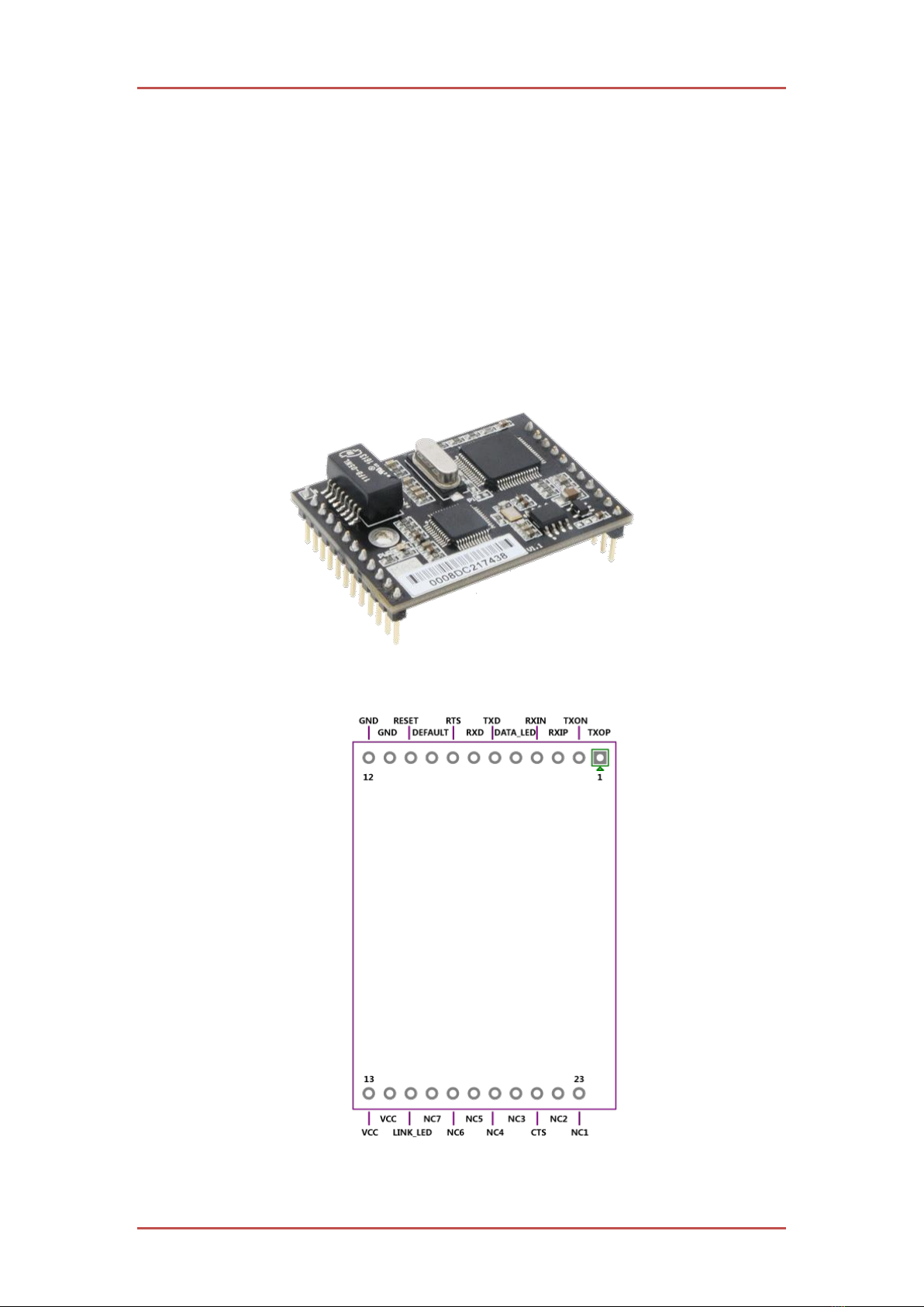
2.1 PINOUTS AND PIN DESCRIPTION.................................................................................. 3
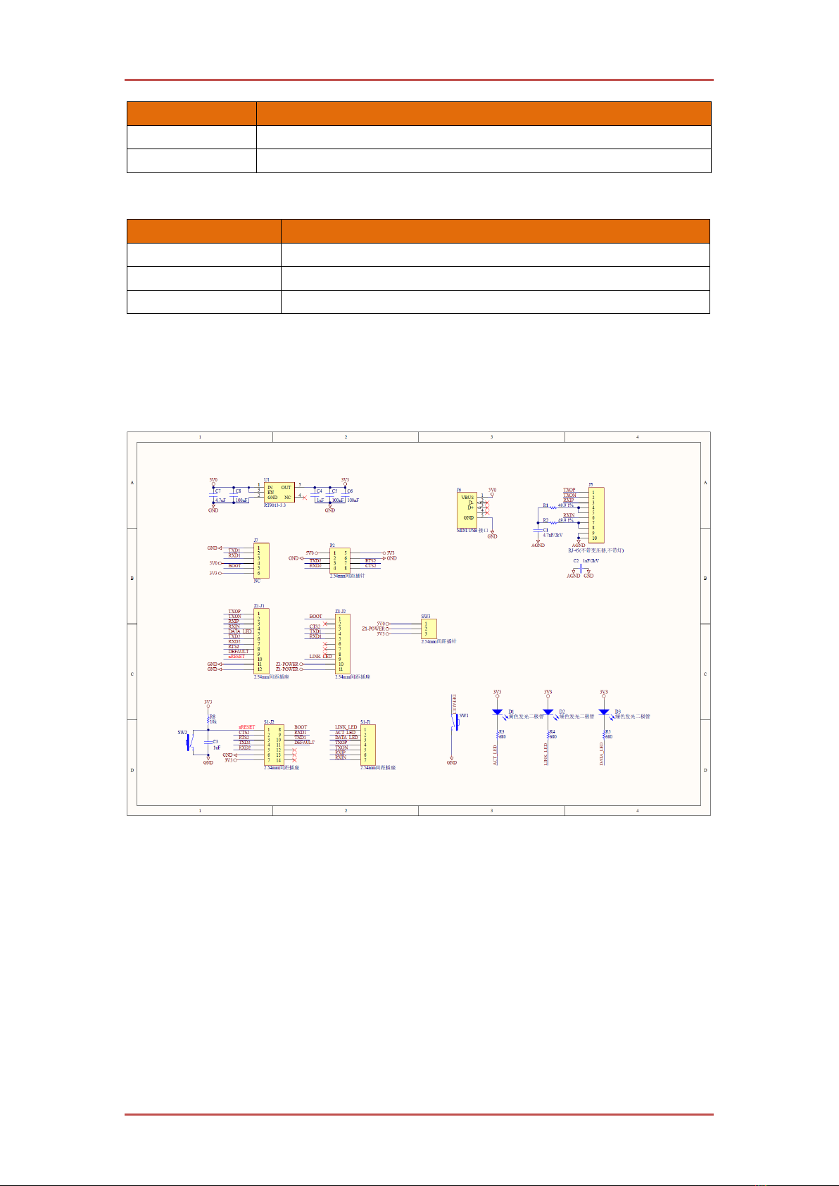
2.2 WIZS2E EVALUATION BOARD .................................................................................... 5
2.3 QUICK TESTING GUIDE................................................................................................ 7
3OPERATING MODES.................................................................................................... 8
3.1 TCP SERVER MODE ..................................................................................................... 8
3.2 TCP CLIENT MODE...................................................................................................... 9
3.3 UDP MODE ............................................................................................................... 10
4IP ADDRESS ...................................................................................................................11
4.1 MODULE IP ADDRESS FACTORY DEFAULT SETTINGS..................................................11
4.2 METHOD TO GET THE IP ADDRESS OF THE MODULE ..................................................11
4.3 MODULE AND HOST COMPUTER NETWORK DETECTION ........................................... 12
4.4 HOW TO SET THE IP ADDRESS OF THE HOST COMPUTER ........................................... 13
5WIZS2E CONFIGTOOL.............................................................................................. 14
5.1 COLLECT MODULE’S SETTING INFORMATION ........................................................... 14
5.2 MODIFY THE DEVICE SETTINGS ................................................................................ 15
5.3 FACTORY RESET........................................................................................................ 15
5.3.1 Factory reset setting by software...................................................................... 15
5.3.2 Factory reset module through AT command..................................................... 15
5.3.3 Hardware factory reset method ........................................................................ 16
5.4 FIRMWARE UPGRADE ............................................................................................... 16
6AT COMMAND CONFIGURATION.......................................................................... 17
6.1 AT COMMAND OVERVIEW......................................................................................... 17
6.2 ENTER AT COMMAND MODE.................................................................................... 18
6.3 AT COMMAND LIST ................................................................................................... 18
6.3.1 System control command list ............................................................................ 18
6.3.2 Control command list........................................................................................ 18
6.3.3 Serial configuration command list.................................................................... 19
6.4 AT COMMAND DETAILS............................................................................................. 21
6.4.1 Basic commands ............................................................................................... 21
6.4.2 Control commands............................................................................................ 21
6.4.3 Device configuration command list.................................................................. 23
6.4.4 Serial control command.................................................................................... 28
6.5 AT COMMAND CONFIGURATION EXAMPLES ............................................................. 32

W5500S2E-Z1 serial to Ethernet module
W5500S2E-Z1 user manual
6.5.1 Set into TCP server mode example................................................................... 32
6.5.2 TCP client mode example ................................................................................. 33
6.5.3 UDP mode example .......................................................................................... 34
7WEB PAGE CONFIGURATION................................................................................. 35
7.1 MAIN PAGE ............................................................................................................... 35
7.2 BASIC SETTINGS ....................................................................................................... 37
7.3 ADVANCE SETTINGS ................................................................................................. 38
7.4 FIRMWARE INFORMATION......................................................................................... 39
7.5 DEVICE MANAGEMENT ............................................................................................. 40
8FIRMWARE UPGRADE .............................................................................................. 42
8.1 W5500S2E-Z1 FIRMWARE UPGRADE THROUGH CONFIGTOOL ................................ 42
8.2 FIRMWARE UPGRADE THROUGH CONFIGURATION WEB PAGE ................................... 43

W5500S2E-Z1 user manual 1
1Introduction
1.1.1 Configuration methods
W5500S2E-Z1 provides three types configuration methods for user to operate with the module.
WIZS2E ConfigTool is a computer software configuration tool. It can be installed and run
in Windows® environment.
Web page configuration allows user locally or remotely to configure the module through
web browser.
AT command configuration support sending serial commands from the mainboard of the
embedded device or from the serial terminal to configure the parameters of WIZS2E
modules.
1.2 Specifications
1.2.1 Electrical characteristics
1.2.1.1 Voltage and current characteristics
The following table 1-1 and 1-2 was the result tested in 25oC environment.
Table 1-1 Voltage and current characteristics
Symbol
Types
Ratings
Min
Normal
Max
Unit
VDD
Module Voltage
2.97
3.3
3.6
V
I
Module Current
101
106
157
mA

W5500S2E-Z1 serial to Ethernet module
W5500S2E-Z1 user manual
1.2.1.2 Current characteristics
Table 1-2 Current characteristics
1.2.2 Dimensions
For fitting the module into your design, please refer to the reference figure 1-1; It shows all the
dimensions of the modules. In the figure, it provides the regulation for three dimensions with the
distance of upper and lower parts pin headers and the location of the one mounting holes. The pin
header has pitch 2.54mm.
Figure 1-1 W5500S2E-Z1 dimensions top view
Figure 1-2 W5500S2E-Z1 dimensions side view
1.2.3 Thermal Characteristics
Table 1-3 Thermal characters
Working Mode
Ratings (mA)
Working Mode
Ratings (mA)
Standby
101
100Mbps without connection
157
10Mbps without connection
106
100Mbps with data communication
157
10Mbps with data communication
106
Part Number
Grade
Operating temperature
Storage temperature
W5500S2E-Z1
Industrial Grade
-40 ~ +85 ℃
-40 ~ +85 ℃

W5500S2E-Z1 serial to Ethernet module
W5500S2E-Z1 user manual
2 Hardware description
2.1 Pinouts and pin description
The following section will introduce W5500S2E-Z1 pin header explanation and the usage of
WIZS2E evaluation board.
The following figure 2-1 is the appearance of WIZS2E module. From this figure, we could identify
there are 3 rows of pin headers on the module as hardware connectors for users. J1 is a 1x12 single
row 2.54mm pin and J2 is 1x11 double row 2.54mm pins.
Figure 2-2 is the pin assignment of W5500S2E-Z1, table 2-1 and 2-2 are the pin header description
of W5500S2E-Z1 module.
Figure 2-1 W5500S2E-Z1 module
Figure 2-2 W5500S2E-Z1 pinout

W5500S2E-Z1 serial to Ethernet module
W5500S2E-Z1 user manual
Table 2-1 W5500S2E-Z1 J1 pin definition
Pin No.
Pin Name
I/O
Function
1
TXOP
O
Ethernet connector TXOP
2
TXON
O
Ethernet connector TXON
3
RXIP
I
Ethernet connector RXIP
4
RXIN
I
Ethernet connector RXIN
5
DATA_LED
O
Ethernet Status Indicator
6
TXD
O
Serial output signal
7
RXD
I
Serial input signal
8
RTS
I/O
Serial RTS signal
9
DEFAULT
I
Active low, pull down over 3s for factory reset
10
RESET
I
Hardware reset pin
11
GND
-
GND
12
GND
-
GND
Table 2-2 W5500S2E-Z1 J2 pin definition
Pin No.
Pin Name
I/O
Function
13
VCC
-
VCC
14
VCC
-
VCC
15
LINK_LED
O
Ethernet link indicator
16
NC7
-
-
17
NC6
-
-
18
NC5
-
-
19
NC4
-
-
20
NC3
-
-
21
CTS
I/O
Serial CTS signal pin
22
NC2
-
-
23
NC1
-
-

W5500S2E-Z1 serial to Ethernet module
W5500S2E-Z1 user manual
2.2 WIZS2E evaluation board
Figure 2-3 WIZS2E evaluation board
WIZS2E evaluation board provides a simple platform for testing and running an application for
WIZS2E modules including W5500S2E-Z1. Where S1-J1 and S1-J2 are used to plug in the
W5500S2E-Z1 module, S1-J1 and S1-J2 are used to plug in other models of WIZS2E module (s),
which are described in the user manuals of the related modules. The evaluation board integrates
RJ45, serial TTL and USB mini interfaces. (The following figure shows “x” means vacant)
RJ-45 (J5) interface Pin Assignment
Pin
Signal
Pin
Signal
1
RXIN
5
×
2
RXIP
6
TXOP
3
TXON
7
×
4
×
8
×
TTL interface (P2) Pin Assignment
Pin
Signal
Pin
Signal
1
5V
5
3V3
2
GND
6
GND
3
TX
7
RTS
4
RX
8
CTS
The USB Mini Interface (J6) Pin Assignment
Note: supply 5 V DC power for the evaluation board only. Not for debug or communication
Pin
Signal
Pin
Signal
1
5V
4
×
2
×
5
GND
3
×
SW3 is power supply pin for other modules, it would be leave open for W5500S2E-Z1
Pin
Signal
Pin
Signal
1
5V
3
3V3
2
Vcc
W5500S2E-Z1 evaluation board buttons introduction
1 2 3 4
5 6 7 8

W5500S2E-Z1 serial to Ethernet module
W5500S2E-Z1 user manual
Marking
Description
SW1 (DEFAULT)
Press switch for 1-3 seconds for module reset, over 3 seconds to factory reset
SW2 (RESET)
Hardware reset button
Figure 2-4 W5500S2E-Z1 evaluation board button description
W5500S2E-Z1 evaluation board LED description
Marking
Description
ACT
Ethernet status indicator
LINK
Ethernet connection indicator
DATA
Ethernet data communication LED, the Blink speed shows the data speed
Table 2-5 W5500S2E-Z1 evaluation board LED description
Hardware connection explanation
W5500S2E-Z1 used two sections of pin layouts in 1 x 7 pin and 2 x 7 pin designs. This is to
avoid plugging the module in the wrong directing which may damage to the module.
Figure 2-4 shows the reference schematic of the evaluation board for developing reference.
Figure 2-4 W5500S2E-Z1 evaluation board reference schematic

W5500S2E-Z1 serial to Ethernet module
W5500S2E-Z1 user manual
2.3 Quick testing guide
WIZS2E module can upgrades products or devices from serial interface to Ethernet interface.
Evaluation board can be used for a quick test before implement the module into the design. By
connection the serial interface to the module and Ethernet interface connected to the host computer,
the user could easily control the serial device through Ethernet as the figure 2-5.
Ethernet
Serial
User Device
PC
Serial Serial
W5500S2E-S1
User Device User Device
W5500S2E-S1 W5500S2E-S1
Figure 2-5 W5500S2E-Z1 module testing evaluation block diagram
Using LAN cables and USB to Serial (TTL)cables to connect from the host computer and to the
respective LAN ports and TTL ports of the evaluation board. This will create a simple testing
network; The IP address of the host computer's wired network card is changed according to the 4.4
chapters, the user can send/receive data through the network port, receive/send from the serial port,
and conduct a simple testing and evaluation.

W5500S2E-Z1 serial to Ethernet module
W5500S2E-Z1 user manual
3 Operating modes
WIZS2E module supports TCP server, TCP client and UDP modes; Below demonstrate these
operating modes.
3.1 TCP server mode
Ethernet TCP/IP
Communication
RS232 Serial
Communication
①Send Link
Request
②Bothway Data
Communication
TCP Client
TCP Server
User Device
Figure 3-1 TCP server mode diagram
Figure 3-1 shows, W5500S2E-Z1 module open a local port to listen TCP requests in TCP server
mode. The default port number is 5000 and it is waiting for client connections. After the connection
has created, it will start data communication.

W5500S2E-Z1 serial to Ethernet module
W5500S2E-Z1 user manual
3.2 TCP client mode
Ethernet TCP/IP
Communication
①Send Link
Request
②Bothway Data
Communication
TCP Server
TCP Client
User Device
RS232 Serial
Communication
Figure 3-2 TCP client mode diagram
According to figure 3-2, W5500S2E-Z1 module will starts to connect to TCP server that set in the
module for TCP client mode. If connection fails, client will base on reconnection setting condition
and try to connect with the TCP server. After its connected, it will start data communication.

W5500S2E-Z1 serial to Ethernet module
W5500S2E-Z1 user manual
3.3 UDP mode
Ethernet TCP/IP
Communication
①Send Link
Request
②Bothway Data
Communication
TCP Server
TCP Client
User Device
RS232 Serial
Communication
Figure 3-3 UDP mode diagram
For UDP mode in Figure 3-3, W5500S2E-Z1 module is required to have the remote IP address and
port number to create an UDP communication. UDP mode communicate is not based on
“connection”. Therefore, it does not guarantee the target device could receive the data correctly or
not. Thus, it requires an upper layer communication protocol to communicate for ensuring the data
accuracy. However, since UDP mode is a simple communication protocol, it could provide a better
communication speed due to less workload on data accuracy. In fact, UDP are not likely to get data
error in network environment under normal workload. In this operating mode, both devices are equal,
and they do not differentiate into server or client.

W5500S2E-Z1 serial to Ethernet module
W5500S2E-Z1 user manual
4 IP address
Before using the module, we need to know some parameters like IP address. This module support
“Static” and “DHCP” IP collection method. For “Static” mode, user could manually change the IP
address, subnet mask & gateway parameters. The emphasis here is that the IP address of the module
cannot be the same as the IP address of other devices in the same LAN. i.e. the module will activate
DHCP protocol to collect IP address, subnet mask and gateway information from the DHCP server.
4.1 Module IP address factory default settings
WIZS2E Serial to Ethernet module’s factory default IP address: 192.168.1.88.
4.2 Method to get the IP address of the module
No matter forgotten the IP address of the module or the module is working on DHCP mode, the
current IP address of the module could be searched using the WIZS2E ConfigTool. The following
steps are the method to use WIZS2E ConfigTool to search the IP address for WIZS2E module:
1. Connect the host computer and the module with LAN cable and power up the module.
2. Run the WIZS2E ConfigTool and it shows as the following 4-1 figure.
Figure 4-1 WIZS2E ConfigTool interface
3. Press button, it shows the IP address information as the following figure 4-2.

W5500S2E-Z1 serial to Ethernet module
W5500S2E-Z1 user manual
Figure 4-2 WIZS2E ConfigTool search result
4.3 Module and host computer network detection
Before starting to communicate between the WIZS2E module and the host computer, please ensure
the host computer and the module are in the same network segment.
The factory default setting for IP address and Subnet mask in WIZS2E module are 192.168.1.88 and
255.255.255.0 respectively. User could follow the flow diagram 4-3 to understand the
communication procedure between the module and the host computer. If they are in the same
network segment, it could communicate with the module. Otherwise, the host computer needs to
change its IP address to communicate with the module.
W5500S2E-S1 IP Address
192.168.1.88 and
W5500S2E-S1 Submask
255.255.255.0
PC Submask
?and
PC IP Address
?
W5500S2E-S1 Subnet
192.168.1.0
PC Subnet
?
Compare
Use W5500S2E-S1 to Communicate Change IP Address
Different SubnetThe Same Subnet
Figure 4-3 WIZS2E module and IP segment of host computer flow diagram

W5500S2E-Z1 serial to Ethernet module
W5500S2E-Z1 user manual
4.4 How to set the IP address of the host computer
The following procedure is based on Windows® 7 Operation System.
Press “Start” → “Control Panel” → “Network Sharing Centre” → “Changing adaptor setting” →
“Local connection” → Right Click “Properties” → Double Click “Internet protocol version 4
(TCP/IPv4)”. After all these procedures, you could get into the result as the following figure shows.
Please choose “Using the following IP addresses” for inputting the IP address as 192.168.1.99, the
subnet mask is 255.255.255.0 and default gateway into 192.168.1.1. The DNS section could ignore.
Finally, please click “Enter” for saving these settings and starts to communicate with WIZS2E
module.
Figure 4-4 Window 7 (Chinese version) IP address setting interface

W5500S2E-Z1 serial to Ethernet module
W5500S2E-Z1 user manual
5 WIZS2E ConfigTool
WIZS2E ConfigTool is a Windows® configuration tool compatibles to W5500S2E and W7500S2E
series modules. WIZS2E ConfigTool can be used to search, enquiry and configure W5500S2E and
W7500S2E device features and information.
5.1 Collect module’s setting information
Click the toolbar’s button, WIZS2E ConfigTool will search all WIZS2E module that has
connected in the same network segment (Direct connect or under the same router). The figure 5-1
shows the result as mentioned. The search section shows all the modules in MAC address format as
the parent node for the list of information of WIZS2E module. By pressing the “ ” button, it shows
the detail information about this module. After pressing the MAC address of that specific module,
it will list out all the IP address, serial interface settings and other parameters of this module. This
information presents on the Basic settings and Advance Option tab that were next to the search
section.
Note: Prior configuration, it is recommended that you disable other unrelated network adapters in
your host computer (including virtual network adapters, if you use the wired network adapter
configuration module to turn off the wireless network card) and ensure that all device IP addresses
in the LAN are not conflicting.
Figure 5-1 WIZS2E ConfigTool basic settings interface

W5500S2E-Z1 serial to Ethernet module
W5500S2E-Z1 user manual
Figure 5-2 WIZS2E ConfigTool advance options interface
5.2 Modify the device settings
After searching the module, user could directly go to “Basic Settings” and “Advance Options” to
configure the module. Please press button to save your configuration.
5.3 Factory reset
If the customer found out some uncertainties with the WIZS2E module, the user could reset the
module back to factory default setting to solve the problem. There are three kinds of method to
factory: Software (ConfigTool), AT command and hardware reset.
5.3.1 Factory reset setting by software
I. In the WIZS2E ConfigTool, please click the module on the search section that needs to
factory reset.
II. Please press toolbar’s → factory reset button to reset the
module back to default settings.
5.3.2 Factory reset module through AT command
For detail information about this AT command (AT+DEFAULT) for factory reset, please refer
section 6.4.2.6.

W5500S2E-Z1 serial to Ethernet module
W5500S2E-Z1 user manual
5.3.3 Hardware factory reset method
5.3.3.1 Factory reset through evaluation board
Figure 5-3 The evaluation board reset button
After providing power to the module, please press the DEFAULT button for more than 3 seconds to
apply factory reset procedure.
5.3.3.2 Factory reset through module
Figure 5‑4 through the module default PIN to restore factory settings
W5500S2E-Z1 has a restored factory set PIN. After power on the module, pull down the DEFAULT
pin for 3 seconds to activate factory default.
5.4 Firmware Upgrade
W5500S2E-Z1 supports host computer firmware upgrade and remote firmware upgrade features
through web page. For detail information, please refer section 8 Firmware upgrade.
Table of contents
Popular Industrial Equipment manuals by other brands

Mitsubishi Electric
Mitsubishi Electric UBC75 Installation, operation & maintenance manual

probst
probst FTZ-UNI-50 operating instructions

Rockwell Automation
Rockwell Automation Allen-Bradley PanelView Plus 400 user manual

Newport
Newport RV user manual

MIYAWAKI
MIYAWAKI TS1 operating manual

ABB
ABB HT571053 Operation manual

Thunderstone
Thunderstone THUNDER POWER TARP 7000 Operation instructions

Full Spectrum Laser
Full Spectrum Laser MUSE TITAN V3 manual

Donaldson Torit
Donaldson Torit LP Series Installation and operation manual

Danfoss
Danfoss DHP-M Commissioning

WURM
WURM LUK-XP quick start guide

FRIEDHELM LOH
FRIEDHELM LOH Rittal 8100.730 Assembly instructions