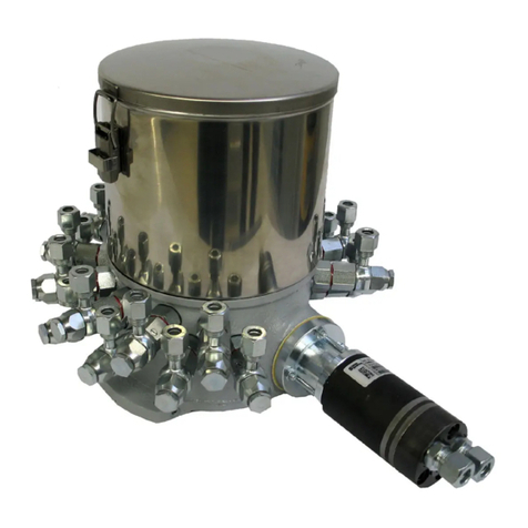
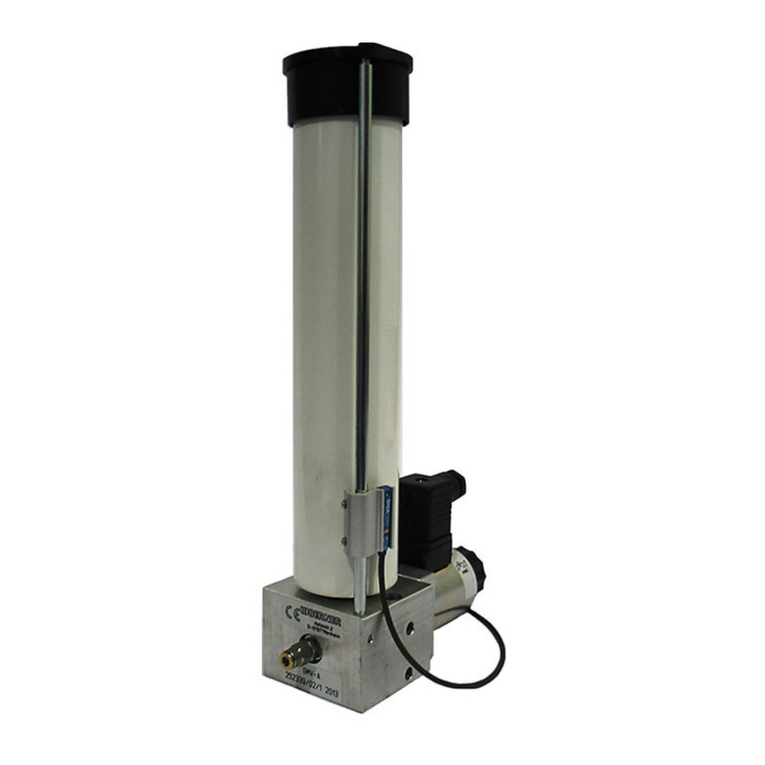
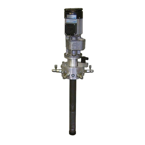
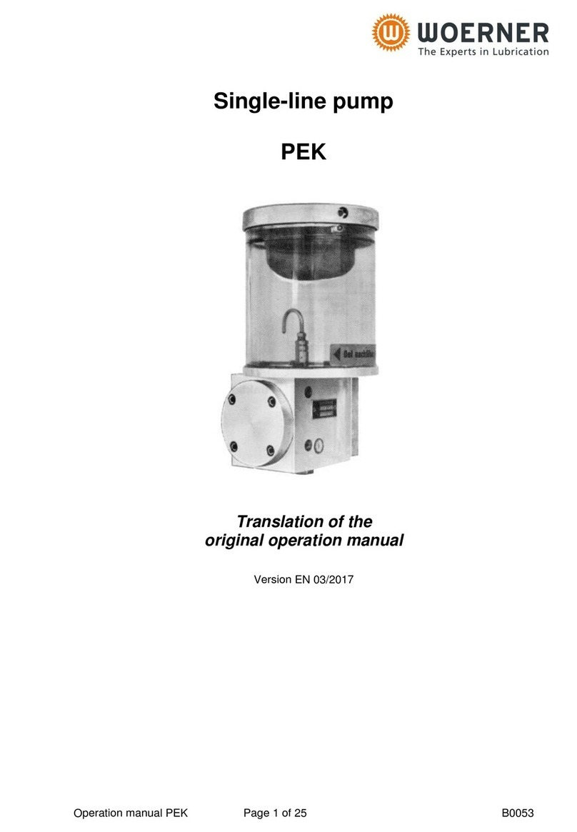
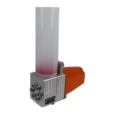
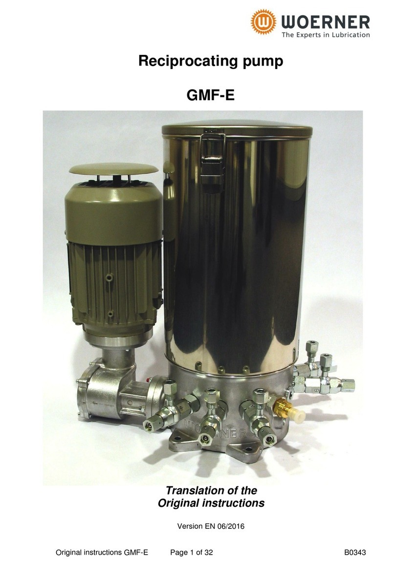
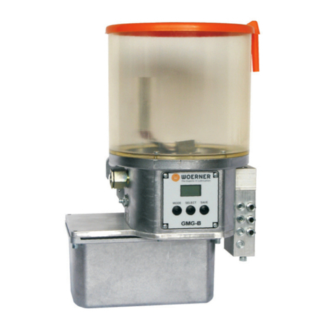
WOERNER GFZ User manual

Operating manual GFZ / GFM / GEZ Page 1 of 30 B0112
Gear-type pump unit
GFZ / GFM / GEZ
Translation of the
original operation manual
Version EN 05/2018

Operating manual GFZ / GFM / GEZ Page 2 of 30 B0112
Translation
When delivery is made into EEC countries, this operation manual
needs to be translated into the user’s country language accordingly.
In case that any inconsistency in the translated text occurs, the
original (German) operation manual should be referred to for
clarification or the manufacturer contacted.
Copyright
Unless permitted explicitly, the dissemination, reproduction, and
utilisation of this document as well as the communication of its
contents are prohibited. Any violation of this stipulation shall involve
the obligation to compensate damage.
All rights reserved.

Operating manual GFZ / GFM / GEZ Page 3 of 30 B0112
Table of contents
1. Important notes on this operation manual.....................................................................5
1.1 Users........................................................................................................................5
1.2 Obligation to read.....................................................................................................5
1.3 What to do in case of questions................................................................................5
1.4 Operation manual.....................................................................................................5
1.4.1 Applicability ..............................................................................................................5
1.4.2 Content and purpose................................................................................................5
1.4.3 Location....................................................................................................................6
1.4.4 Meanings of safety notes and safety symbols...........................................................6
2. Identification....................................................................................................................7
2.1 Product brand and type designation .........................................................................7
2.2 Product version.........................................................................................................7
2.3 Product marking .......................................................................................................7
2.4 Manufacturer and contact address............................................................................7
2.5 Conformity................................................................................................................7
3. Product description.........................................................................................................8
3.1 Purpose of use .........................................................................................................8
3.2 Limits of use.............................................................................................................8
3.3 Ambient conditions...................................................................................................8
3.4 Conventional usage..................................................................................................9
3.5 Technical data..........................................................................................................9
3.5.1 Assemblies...............................................................................................................9
3.5.2 Dimensions...............................................................................................................9
3.5.3 Technical data..........................................................................................................9
4. Functional description ..................................................................................................10
4.1 Components...........................................................................................................10
4.1.1 GFZ-B, GFZ-C, GFZ-D...........................................................................................10
4.1.2 GFZ-N....................................................................................................................10
4.1.3 GFZ-L / GFZ-L01....................................................................................................10
4.1.4 GFM-F, GFM-G......................................................................................................10
4.1.5 GFM-N....................................................................................................................10
4.1.6 GFM-L / GFM-L01..................................................................................................10
4.1.7 GEZ-B / GEZ-C ......................................................................................................10
4.2 Energy supply.........................................................................................................10
4.3 Function..................................................................................................................11
5. Safety notes...................................................................................................................11
5.1 Basic principle ........................................................................................................11
5.2 Requirements on user training................................................................................11
5.3 Safety facilities........................................................................................................12
5.4 Accident prevention................................................................................................12
5.5 Residual risks.........................................................................................................12
5.6 Incorrect applications..............................................................................................12
5.7 General safety regulations and duties.....................................................................13
5.8 Special features of the types meeting the requirements of the directive 2014/34/EU
(ATEX)...............................................................................................................................14
5.9 Disclaimer...............................................................................................................14
6. Transportation, installation, commissioning and shutdown......................................15
6.1 Transportation ........................................................................................................15
6.2 Unpacking ..............................................................................................................15
6.3 Installation..............................................................................................................15
6.3.1 GFZ series..............................................................................................................15

Operating manual GFZ / GFM / GEZ Page 4 of 30 B0112
6.3.2 GFM series.............................................................................................................16
6.3.3 GEZ series .............................................................................................................16
6.4 Power supply and switch-on...................................................................................16
6.5 Commissioning.......................................................................................................16
6.6 Shutdown ...............................................................................................................18
7. Operation .......................................................................................................................19
7.1.1 Troubleshooting, fault remedy ................................................................................19
7.2 Refilling the reservoir..............................................................................................20
7.3 Switch-off................................................................................................................20
8. Cleaning, servicing, fault remedy, and repair..............................................................21
8.1 Cleaning.................................................................................................................21
8.2 Servicing.................................................................................................................21
8.3 Inspection schedule................................................................................................22
8.4 Repair.....................................................................................................................22
8.5 Accessories............................................................................................................25
8.5.1 Pressure relief valve for GFM-F pump until GFM-G pump:.....................................25
8.5.2 Pressure relief valve for GEZ-B pump until GEZ-C pump: ......................................25
9. Return shipment to factory...........................................................................................26
10. Disposal...................................................................................................................28
11. Appendix..................................................................................................................28
11.1 Content of the declaration of conformity..................................................................28
11.2 Content of declaration of incorporation ...................................................................28
11.3 Declaration of conformity........................................................................................29
11.4 Technical data of the pump units............................................................................30
11.5 Data sheets............................................................................................................30

Operating manual GFZ / GFM / GEZ Page 5 of 30 B0112
1. Important notes on this operation manual
This operation manual forms part of the machine and must be available
to the operation and maintenance personnel at any time.
The safety notes contained herein need to be observed. When reselling
the machine, this operation manual must be handed over in any case as
well.
In addition to this operation manual, always be careful to observe the
laws and regulations being applicable in the country of use.
1.1 Users
This operation manual is intended for technically qualified users, who have been instructed
or trained in the operation of the pump unit.
1.2 Obligation to read
As an operator and user of the pump unit, you are obliged to read and understand this
operation manual and, in particular, its section "Safety regulations". It is your safety that is at
stake! Should you have any question or uncertainty, contact WOERNER, please.
1.3 What to do in case of questions
In case of questions that you cannot solve by means of this operation manual, WOERNER
will help you. In such situations it is indispensable that you provide us with a precise
description of the problem at stake.
1.4 Operation manual
1.4.1 Applicability
This operation manual is applicable to the series versions of the gear-type pump units GFM,
GFZ and GEZ. Should any part thereof be related to particular versions only, special
reference will be made.
1.4.2 Content and purpose
This operation manual contains the relevant information for the commissioning, operation
and maintenance of the pump unit. It is designed to help you in using the pump unit properly,
efficiently and safely.

Operating manual GFZ / GFM / GEZ Page 6 of 30 B0112
1.4.3 Location
This operation manual must always be available to the users at their places of work.
1.4.4 Meanings of safety notes and safety symbols
Safety notes
In this operation manual, the pictograms and key words for safety instructions, precautions,
and notes have the following meanings:
Danger! Any danger threatening immediately and capable of causing
serious personal injuries.
Warning! Any possibly dangerous situation capable of causing serious
personal injuries.
Caution! Any possibly dangerous situation that might cause minor
personal injuries.
Caution! Warning about property damage.
Note! Any possibly harmful situation in which the product itself or an
object in its close vicinity might be damaged.
Important! Notes on application and other useful information facilitating the
proper usage of the product.
Danger! Any danger threatening immediately due to the presence of
electric current that may cause serious personal injuries.

Operating manual GFZ / GFM / GEZ Page 7 of 30 B0112
2. Identification
2.1 Product brand and type designation
Piston pump unit manufactured by Eugen Woerner GmbH & Co. KG
Product type:
GFM-F, GFM-G, GFM-N, GFM-L, GFM-L01
GFZ-B, GFZ-C, GFZ-D, GFZ-N, GFZ-L, GFZ-L01
GEZ-B, GEZ-C
2.2 Product version
Version as of model year 2015
2.3 Product marking
The type label is located at the side of the pump body and contains information as follows:
Manufacturer
Type (GFM-F)
No. <order number> (e.g. 612345/1)
Model year
2.4 Manufacturer and contact address
Eugen Woerner GmbH & Co. KG
Hafenstrasse 2
D-97877 Wertheim
Phone +49 9342 803-0
Facsimile +49 9342 803-202
Net www.woerner.de
E-Mail info@woerner.de
2.5 Conformity
The pump unit is in conformity with the EC directive on machinery (2006/42/EC).
For the content of the declaration of conformity see the appendix (section 11).

Operating manual GFZ / GFM / GEZ Page 8 of 30 B0112
3. Product description
3.1 Purpose of use
The pump unit is designed for the delivery of lube oils exclusively.
3.2 Limits of use
The application area of the pump unit’s components is restricted as follows:
Type:
GFM-F
GFM-G
GFM-N
GFM-L
GFM-L01
GFZ-B
GFZ-C
GFZ-D
GFZ-N
GFZ-L
GFZ-L01
GEZ-B
GEZ-C
Medium:
Mineral oil
Viscosity:
100 … 1350
cP
16 … 1350 cP
100 … 1350
cP
16 … 1350 cP
16 … 1520
cP
Medium
temperature:
-20 … +80 °C
-15 … +80 °C
-20 … +80 °C
-15 … +80 °C
-20 … +130
°C
Ambient
temperature:
-20 … +40 °C
-20 … +40 °C
-20 … +40 °C
-20 … +40 °C
-20 … +50
°C
Permissible
negative
pressure:
-0,3 bar
-0,3 bar
-0,3 bar
-0,3 bar
-0,3 bar
Operating
pressure1):
see technical details chapter 11.5
Flow rate1)2):
1)The maximum permissable values of your pump unit can be found in chapter 11.5.
2)The volume flow is dependend on the viscosity of the lubricant, operating pressure and
pump rotation.
Besides, the pump unit’s area of application is determined by the medium to be delivered.
Hence, when determining the area of application, you also need to refer to the technical data
sheets for the medium to be used.
3.3 Ambient conditions
Pump unit operation in an aggressive atmosphere (solvent vapours,
acids, lyes, salt water mist, etc.) may cause damage to or corrosion of
components and, thus, failure of the system and endangerment due to
leaking lubricant!
Ambient temperature range
Lower temperature limit: -20 °C
Upper temperature limit: +40 °C
Relative humidity: max. 70%
Noise level: <70 dB(A)
Physical environment
In heights as of 1.000 metres above sea level, the system should be operated after
consultation with the manufacturer only.

Operating manual GFZ / GFM / GEZ Page 9 of 30 B0112
3.4 Conventional usage
The pump unit is exclusively designed for the delivery of lubricating oils or lubricating
greases in central lubrication systems. Conventional usage also includes:
the observance of the safety notes and adherence to the safety regulations contained
in this operation manual,
the adherence to the maintenance and servicing instructions given in this operation
manual.
Any usage contrary hereto or going beyond the conventional one may
cause serious personal and property damage.
The delivery of gases, liquefied gases, gases dissolved under pressure,
vapours, and liquids the vapour pressure of which exceeds, at the permissible
maximum temperature, the normal atmospheric pressure (1013 mbar) by
more than 0,5 bar, as well as that of highly inflammable or explosive media
and foodstuff is prohibited!
Important! Please also note the safety data sheets pertaining to the
materials used.
3.5 Technical data
3.5.1 Assemblies
The pump unit consists of 3 components:
Gear pump
Flange
Electric motor
3.5.2 Dimensions
The dimensions of the pump unit in use can be found on the data sheets in chapter 11.5.
3.5.3 Technical data
The technical details of the pump unit in use can be found on the data sheets in chapter
11.5.

Operating manual GFZ / GFM / GEZ Page 10 of 30 B0112
4. Functional description
4.1 Components
4.1.1 GFZ-B, GFZ-C, GFZ-D
See data sheet P0149 in chapter 11.5
4.1.2 GFZ-N
See data sheet P0121 in chapter 11.5
4.1.3 GFZ-L / GFZ-L01
See data sheet P0604 / P0849 in chapter 11.5
4.1.4 GFM-F, GFM-G
See data sheet P0399 in chapter 11.5
4.1.5 GFM-N
See data sheet P0120 in chapter 11.5
4.1.6 GFM-L / GFM-L01
See data sheet P0112 / P0847 in chapter 11.5
4.1.7 GEZ-B / GEZ-C
See data sheet P0058 in chapter 11.5
4.2 Energy supply
Connect the motor of the pump unit to the local energy supply. Be careful to observe the
permissable nominal voltage of the motor and power supply.
The technical details of the motors can be found in chapter 11.5. The pump unit has to be
protected adequately.
The electric wiring in accordance with DIN VDE 1000-10 may be done
by qualified electricians only.

Operating manual GFZ / GFM / GEZ Page 11 of 30 B0112
4.3 Function
The lubricant is absorbed through the suction hole of the gear pump. The move of the two
interdigitating gear pumps causes a pressure increase of the lubricant. The lubricant is
delivered from the gear pump aggregate to the connection for the pressure line.
The pump units of the GFZ series include pressure relief valves. With these pressure relief
valves, the maximum pressure in the feed pipe can be adjusted.
The pump units of the GFZ series include pressure relief valves. With these pressure relief
valves, the maximum pressure in the feed pipe is adjusted.
5. Safety notes
5.1 Basic principle
The pump unit leaves the factory in flawless condition and ensures high technical safety.
The pump unit is in conformity with the rules of technology and the applicable safety and
health regulations. Nevertheless, in case of incorrect operation or misuse, risks are
threatening to the:
lives and bodies of the users or third parties,
pump unit or other operator assets,
efficient use of the pump unit.
5.2 Requirements on user training
Any person getting to work on the pump unit must be authorised and trained for that purpose
by the operator. They must be able to recognise and avoid potential risks. This also includes
knowledge in the accident prevention regulations, first-aid measures, and local rescue
facilities.
The unit may be inspected, maintained and repaired by technically skilled
personnel with product-specific training only.
Work on electric facilities may be performed by skilled electricians in
conformity with DIN VDE 1000-10 only.
Qualified personnel with product specific education is responsible for the planning and
controlling of the work.

Operating manual GFZ / GFM / GEZ Page 12 of 30 B0112
5.3 Safety facilities
Mechanically, the pump unit is built intrinsically safe.
During operation of the pump unit, be careful to observe the security
regulations being applicable in the country of use.
5.4 Accident prevention
For accident prevention, take these measures:
Prevent unauthorised persons from accessing the pump unit.
Keep foreign persons away from the areas and places of risk.
Inform present foreign persons about residual risks repeatedly. Inform yourself about such
risks in the "Residual risks" section.
5.5 Residual risks
When using the pump unit properly and adhering to the maintenance and repair cycles and
measures prescribed, there are no residual risks to persons and objects within the pump
unit’s area.
5.6 Incorrect applications
Any usage contrary hereto or going beyond the conventional one may cause
serious personal and property damage.
As experience shows, possible incorrect applications include, for instance, the following:
the delivery of highly inflammable or explosive media,
the delivery of media being capable of reacting with the materials used for the pump
unit,
the delivery of foodstuff.

Operating manual GFZ / GFM / GEZ Page 13 of 30 B0112
5.7 General safety regulations and duties
Basically, the following safety regulations and duties are applicable to the use
of the pump unit:
The generally accepted rules for work safety need to be
observed. Besides, the basic regulations and rules on work
safety and accident prevention being applicable to the place of
use have to be followed.
When using the pump unit inside vehicles, the generally
accepted traffic law-related rules need to be observed.
The user is obliged to observe the regulations pertaining to the
use of working appliances.
The pump unit must be operated in flawless and clean condition
only.
It is prohibited to remove, modify, bridge or bypass any and all
protection, safety or monitoring facilities.
It is prohibited to reconstruct or modify the pump unit.
The operator should be notified of any fault or damage
immediately.
For repair, no others than original spare parts may be used.
The operator is required to regularly check and maintain all
protection, safety, and monitoring facilities.
After every repair, the flawless condition of the pump unit must
be ensured by means of a test run.

Operating manual GFZ / GFM / GEZ Page 14 of 30 B0112
5.8 Special features of the types meeting the requirements of the directive
2014/34/EU (ATEX)
The gear pump is designed to work within the temperature range
from -20 to +40 °C.
Install the gear pump apart from electrical production equipment.
(EN1127-1 sections. 5.3.5 … 5.3.9)
Connect the gear pump and all the metallically as well as
electrically insulated attached components to the existing
potential equalisation installation. Connect the pipes and
attached components to ground.
Make sure that parts made from synthetic material as well as
cables will not become charged.
If within the equipment a potential equalisation or a component
connected to the potential equalisation system is detached from
a metal part, for example, in case of repair, then install a
connecting line of appropriate cross-section for bridging that part,
when an electrically conducting line was interrupted.
While cleaning and installing, avoid any igniting sparks due to
friction and blows, in every case.
Replace corroded components.
Consider the operating manuals, in particular the ones of
electrical components, too.
As for drive assemblies, which do not comply with the operating
manual, the user has to carry out an ignition hazard assessment.
Electric motor-based drives with EC-type approval are the only
ones allowed to be used.
In case of failures and/or defects, the pump shall be exclusively
checked and repaired by trained staff or WOERNER themselves.
Dismount the pump and handle the single parts exclusively
outside of that area, which is subject to explosion hazard.
5.9 Disclaimer
Should any damage be caused to persons, objects, the environment and/or property due to
the non-observance of this operation manual, no matter whether intentionally or
unintentionally, WOERNER shall be held harmless thereof. Besides, all warranty claims will
be rejected. The same also applies to any and all consequential damage.

Operating manual GFZ / GFM / GEZ Page 15 of 30 B0112
6. Transportation, installation, commissioning and shutdown
6.1 Transportation
Transport the pump unit to its destination carefully and by using suitable aids (e.g. hand-carts
or the like).
6.2 Unpacking
Lift the pump unit out of its packaging carefully and put it on a stable and plane base.
Note! The pump unit and the components attached in accordance with
the scope of delivery may still contain residues of blue-dyed test oil.
6.3 Installation
For the suction connection please choose a suction pipe with an adequate diameter.
The suction side of the suction pipe has to have an angled opening.
Note! The maximum suction height of the gear pump unit is 800 mm.
The maximum suction pipe length is 1000 mm. The permissible
negative pressure in the suction line is -0.3 bar.
6.3.1 GFZ series
Hole pattern of the GFZ-B pump until –D, GFZ-N, GFZ-L, GFZ-L01 please see data sheets
chapter 11.5.
Connect a suction pipe to the suction connection. Lead back the return pipe to the reservoir.
The pump unit is assembled to the top side of the lubricant reservoir. For the assembly a
corresponding hole pattern has to be made on the reservoir. Make sure that the fixing
surface is even and stable enough to carry the pump unit.
If required a flat seal can be put between flange and reservoir. The pump unit is bolted by
means of 4 screws.

Operating manual GFZ / GFM / GEZ Page 16 of 30 B0112
6.3.2 GFM series
Hole pattern of the GFM-F, GFM-G, GFM-N, GFM-L, GFM-L01 please see data sheets
chapter 11.5.
The pump unit is assembled to the mounting points of the motor. The assembly is effected by
4 screws. Make sure that the fixing surface is even and stable enough to carry the pump unit.
Connect a suction pipe to the suction connection. Lead back the return pipe to the reservoir.
6.3.3 GEZ series
Hole pattern of the GEZ-B and GEZ-C please see data sheets chapter 11.5.
Connect a suction pipe to the suction connection. Lead back the return pipe to the reservoir.
The pump unit is assembled to the top side of the lubricant reservoir. For the assembly a
corresponding hole pattern has to be made on the reservoir. Make sure that the fixing
surface is even and stable enough to carry the pump unit.
If required a flat seal can be put between flange and reservoir. The pump unit is bolted by
means of 4 screws.
6.4 Power supply and switch-on
Important! Be careful to compare the data of the local voltage supply with
that given under "Technical data".
Important! Lay the power supply cable such that it cannot be torn off
inadvertently.
Important! Connection work may only be done by qualified personnel.
Work on electric facilities may only be performed by skilled electricians in
conformity with DIN VDE 1000-10.
Connect the pump unit to the voltage supply.
Check the electric connections for correct installation prior to commissioning.
6.5 Commissioning
The pump unit‘s functionality has been checked in the factory.
Hence, it is ready for operation and can be connected to a local voltage supply.

Operating manual GFZ / GFM / GEZ Page 17 of 30 B0112
Important: Note the safety instructions contained in the "Power supply and
switch-on" section.
First fill lubricant and then start the pump unit, in every case.
To ensure flawless functioning, the filling level must not
be lower than 10-15 mm above the reservoir’s bottom
edge.
Commissioning procedure:
a) Filling the pump with lubricant
The pump units may be operated with clean oil only!
The pump unit may not be operated without lubricant over a longer period of
time.
Avoid a dry running condition of the pump unit.
Fill the reservior with lubricant. The pump unit is self-priming. Because of this, no air has to
be removed, generally.
Connect the lubrication point piping.
The lube point lines must be clean and free of any obstruction.
If the pump unit is equipped with an adjustable pressure relief valve, open it.
Warning! If the pump unit is not already fitted with pressure control valves
on delivery, the lube lines need to be retrofitted with suitable
protective elements in order to prevent the pump unit and lube
lines from overloading.
Switch the pump unit on. When lubricant comes out of the lubrication point pipes, the
pressure relief valve can be adjusted to the desired operating pressure.
Warning! Any pump pressure above the admissible operating pressure
may result in the destruction of the system and situations
endangering health!

Operating manual GFZ / GFM / GEZ Page 18 of 30 B0112
6.6 Shutdown
The unit is shut down when switched off and disconnected from the external power supply.
Work on electric facilities may only be performed by skilled electricians
in conformity with DIN VDE 1000-10.

Operating manual GFZ / GFM / GEZ Page 19 of 30 B0112
7. Operation
7.1.1 Troubleshooting, fault remedy
Fault
Root cause
Remedy
Motor does not start
running when
switching on the
voltage supply.
Voltage supply to the
pump motor is interrupted.
Check the power supply.
Check the connection to the
voltage supply.
Check the operating voltage of
the motor and voltage supply.
Check the fuses / motor
protection switches.
If the following work is done, disconnect the pump unit from
the supply voltage
Pump is blocked.
Disassemble the pump and
check the pump for a smooth run.
In case of a blockade, exchange
the pump.
Disassemble the motor and
check the motor for a smooth run.
In case of a blockade, exchange
the motor.
Motor does not work.
Lubricant is not
appropiate for use.
Change the lubricant of the complete
lubrication system.
System pressure is too
high.
Check the function of the pressure
control valve.
Ambient temperature is
too low.
Increase the ambient temperature.
If the following work is done, disconnect the pump unit from
the supply voltage
Pump / Motor fix.
Disassemble the pump and
check the pump for a smooth run.
In case of a blockade, exchange
the pump.
Disassemble the motor and
check the motor for a smooth run.
In case of a blockade, exchange
the motor.

Operating manual GFZ / GFM / GEZ Page 20 of 30 B0112
Fault
Root cause
Remedy
No build of
pressure.
Air in the delivery pipe.
Deaerate the pipe lines.
Pipe line is leaking.
Remove the leakage.
Pressure relief valve does
not close.
Check the pressure relief valve for
correct opening pressure.
Check the pressure relief valve for
dirt. Clean it, if necessary.
Check the pressure relief valve for
damages. Exchange it, if necessary.
Lubricant is not appropiate
for use.
Change the lubricant of the complete
lubrication system.
Reservoir is empty, pump
unit absorbs air.
Re-fill lubricant.
If the following work is done, disconnect the pump unit from the
supply voltage
Pump unit is defective.
Send the pump unit back to Woerner for
testing.
Should the above mentioned troubleshooring and the corresponding remedies not lead to a
flawless operation of the pump unit, turn to WOERNER, please.
7.2 Refilling the reservoir
Only fill clean lubricant into the reservoir. During refilling pay attention that no dirt gets into
the reservoir.
7.3 Switch-off
The unit is switched off by disconnecting it from the power supply.
This manual suits for next models
15
Table of contents
Other WOERNER Water Pump manuals

WOERNER
WOERNER GMV-B User manual

WOERNER
WOERNER GMG-B User manual

WOERNER
WOERNER GMV-A User manual

WOERNER
WOERNER GMG-B User manual

WOERNER
WOERNER GMK-A User manual

WOERNER
WOERNER GMA User manual

WOERNER
WOERNER GMG-K User manual

WOERNER
WOERNER GMF-S01 User manual

WOERNER
WOERNER GMG-LEZ User manual

WOERNER
WOERNER GMA User manual
Popular Water Pump manuals by other brands

IMP PUMPS
IMP PUMPS NMTD SAN MAX II 32-120 Installation and operating manual

Dover
Dover Wilden Advanced P400 Engineering, operation & maintenance

FLORABEST
FLORABEST FTP 400 B2 translation of original operation manual

Oleo-Mac
Oleo-Mac 10 Use and maintenance manual

Little Giant
Little Giant HRK-360S quick start guide

Hitech
Hitech SB-2005 manual