Leaflet-No. 0301 EN
Page 4 of 6
Leaflet-No. 0301 EN
Page 3 of 6
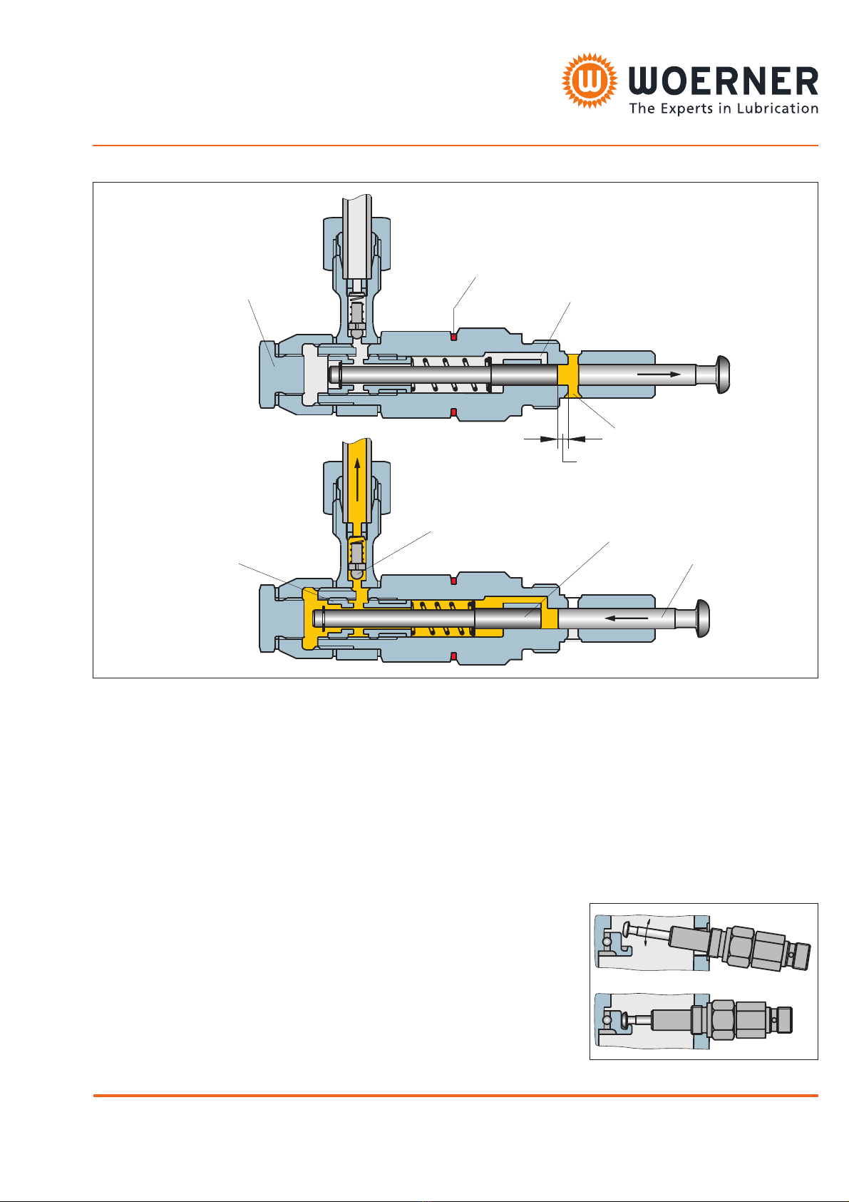
Operation of pump elements:
The suction stroke (fig. 1) is accomplished
by the delivery piston (1) and the control
piston (2). During that operation the delivery
piston (1) is actuated by the eccentric shaft,
and the control piston (2) by the spring. The
control piston closes the pressure hole (3)
and, depending on the set delivery capacity,
remains at a certain position. With the
delivery piston moving on, a vacuum will
build up within the dosage area. After
opening the suction hole (4) by the delivery
piston, the lubricant starts to be sucked off
the reservoir.
In case of pressure stroke (fig. 2) the
delivery piston (1) moves to the left. As a
result, the suction hole (4) will be closed
with the lubricant available between the
delivery and control pistons (2) being
shifted until it clears the pressure hole (3)
and the lubricant is delivered through the
delivery piston up to the outlet. The pumps
are supplied with their delivery capacities
being set at maximum, i.e. at full stroke
setting.
Delivery volume adjustment:
The can be adjusted
continuously between 25 and 100% of the
nominal delivery volume. After having
removed lock screw , the stroke is to be
changed by means of the enclosed spanner
through adjustment nipple . When turning
the nippe to the right, delivery volume will
decrease. At the adjustment nipple, there is
a hexagon against which a spring loaded
piston is pressing radially. Thus, any
independent change of the delivery volume
will be prevented. At the same time, the
latching serves as a measure for setting the
delivery volume. Six latches equal one
rotation of the adjustment nipple and a
reduction of the nominal delivery volume by
33%. 14 latches (minimum) equal a delivery
volume reduction down to 25% of the
nominal delivery volume.
delivery volume
7
6
The element with a piston diameter of
8 mm = 0,15 cm³/stroke is marked with a red
ring (see fig. 1).
Installation of pump elements:
If another pump element is to be installed in
the lubrication pump subsequently, proceed
as shown in the drawing on the right:
Insert pump element at an upwards
inclination into the locating hole with the
plunger pulled out about half way. To
facilitate installation and putting into
operation, fill the bore taking up the plunger
with grease. Bring into horizontal position
and screw in only after the plunger head
abuts the pressure ring and engages in the
groove of the pressure ring.
Reservoir / level monitoring:
When using a "K" sequence piston, the
utilisable reservoir capacity decreases by
approx. 2,5l.
I = Filling connector
(Connection thread G3/8)
II = Return connector G1/8
Remark on the dimensional drawings:
Level monitoring suitable for
delivery of
without level
monitoring
Oil as of 20cP
grease up to
NLGI-cl. 2
Float Oel as of 20cP
Proximity
switch
Grease of NLGI-
cl.1 and 2
Follow-up
piston
Grease up to
NLGI-cl. 2
Reservoir
capacity
Level monitoring
options
Float:
at min. level
Proximity switch:
signal intermit-
tently, min. level
Float:
at min. and
max. level
Proximity switch:
signal intermit-
tently, min. level
Float:
at min. and
max. level
Follow-up piston:
at min. and
max. level
Reservoir
capacity Reservoir material
Polycarbonate
transparent
Polyamide
transparent
Zinced steel
Polyester
fibreglass reinforced
Type A [mm] Weight [kg]
Type B [mm] Weight [kg]
Fig. 1 Suction stroke
Fig. 2 Delivery stroke
Plug (7)
red ring marking the element with
piston 8 = 0,15 cm³/strokeÆ
Pressure passage (3)
Suction opening (4)
Adjusting nipple (6)
Check valve (5)
Control spool (2)
Delivery plunger (1)
Delivery volume
Motor speed 1 / 4,5 25
EUGEN WOERNER GmbH & Co. KG
Postfach 1661 DE-97866 Wertheim
Am Eichamt 8 DE-97877 Wertheim
Tel. +49 (0) 9342 803-0
Fax.+49 (0) 9342 803-202 www.woerner.de
info@woerner.de
EUGEN WOERNER GmbH & Co. KG
Postfach 1661 DE-97866 Wertheim
Am Eichamt 8 DE-97877 Wertheim
Tel. +49 (0) 9342 803-0
Fax.+49 (0) 9342 803-202 www.woerner.de
info@woerner.de
- Subject to modifications -
- Subject to modifications -