8
PRD-06983 REV. 2, December 2023 BM Module Platform Mounting Guide
© 2023 Wolfspeed, Inc. All rights reserved. Wolfspeed® and the Wolfstreak logo are registered trademarks and the Wolfspeed logo is a trademark of Wolfspeed,
Inc. Other trademarks, products, and company names are the property of their respective owners and do not imply specific product and/or vendor endorsement,
sponsorship, or association. The information in this document is subject to change without notice. This document is provided for informational purposes only
and is not a warranty or a specification. For product specifications, please see the data sheets at www.wolfspeed.com.
Provisions for Vibrations
Vibrations over time have the potential to cause a failure in any inverter. For applications where vibrations are
expected, it is important to minimize the amount of force that vibrations will induce at the interfaces. The
module itself is a stiff object and is subject to vibrations as part of the qualification process. However, in
applications, the entire system will be subject to vibrations. This will include not only the module, but also the
interfaces between the module and the system. Thus, it is crucial to understand how the vibration environment
will affect the module and all its interfaces. The following sections provide guidance to maximize device lifetime
in environments where vibrations are a concern.
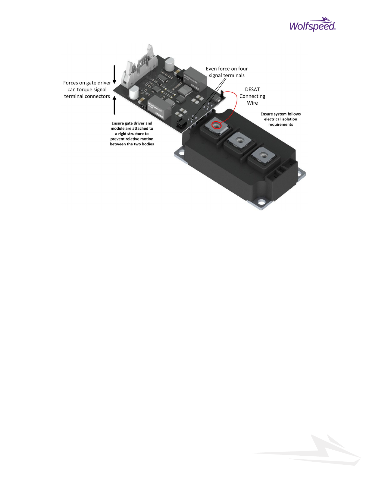
When mounting the BM power module into an application, the mechanical structure of the system should be
scrutinized to ensure that the bussing connecting to the power terminals 1) does not place excessive shear force
on the power terminals and 2) limits the possibility of forces pulling the terminals away from the module. This
is particularly important for systems that may be subject to shock and vibration conditions.
5.1 Cold Plate Vibrations
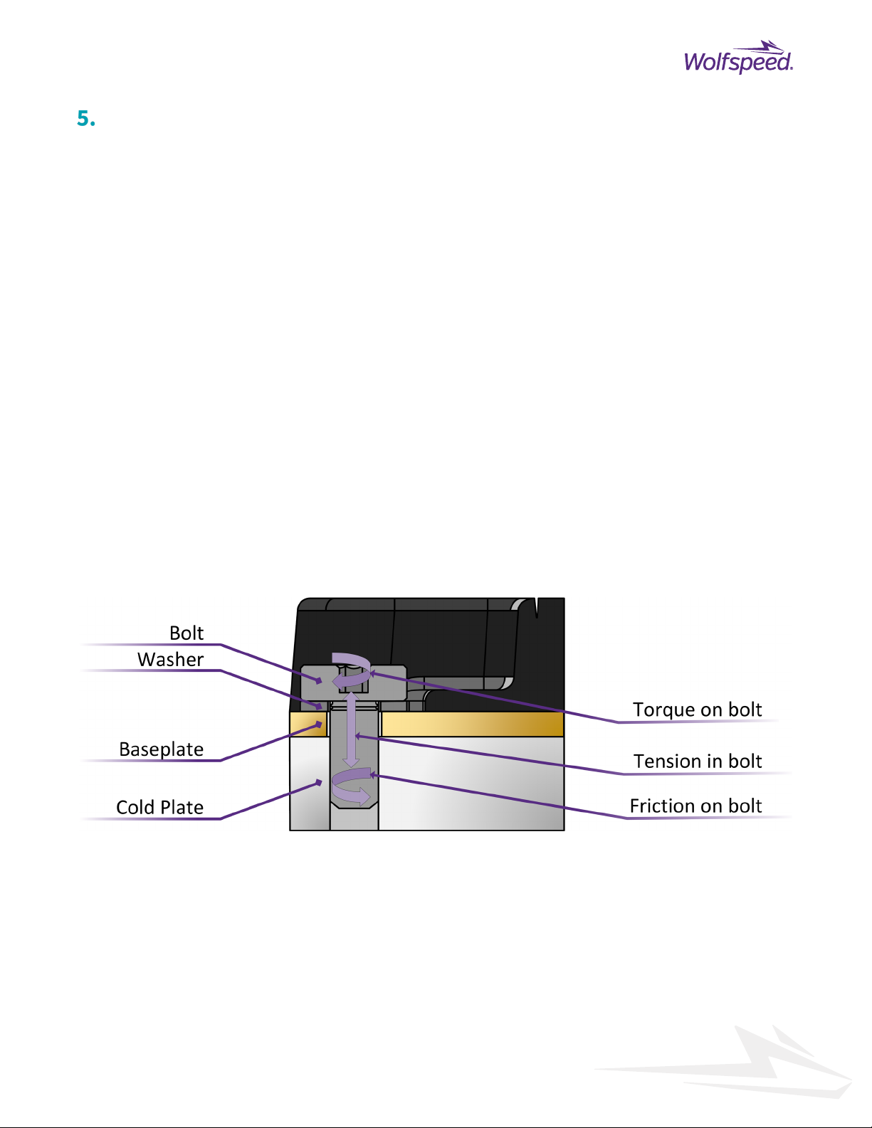
A core point is that the power terminal and cold plate interfaces depend on bolted elements. Bolts are, in effect,
stiff springs; the torque on the bolt induces a force on the threads to create friction that keeps the part fixed, as
shown in Figure 5 below. A key design element is ensuring that vibration does not induce a counter force in the
interface that will overcome the torque induced force, which can cause the bolt to loosen. Under all
circumstances, this bolted interface must be under tension. While solutions such as lock washers, fixing
compounds or bolts with inserts can be used to assist the frictional resistance, they should not be used in lieu
of the above recommendation.
Figure 5: Side cutaway of a baseplate bolt interface.
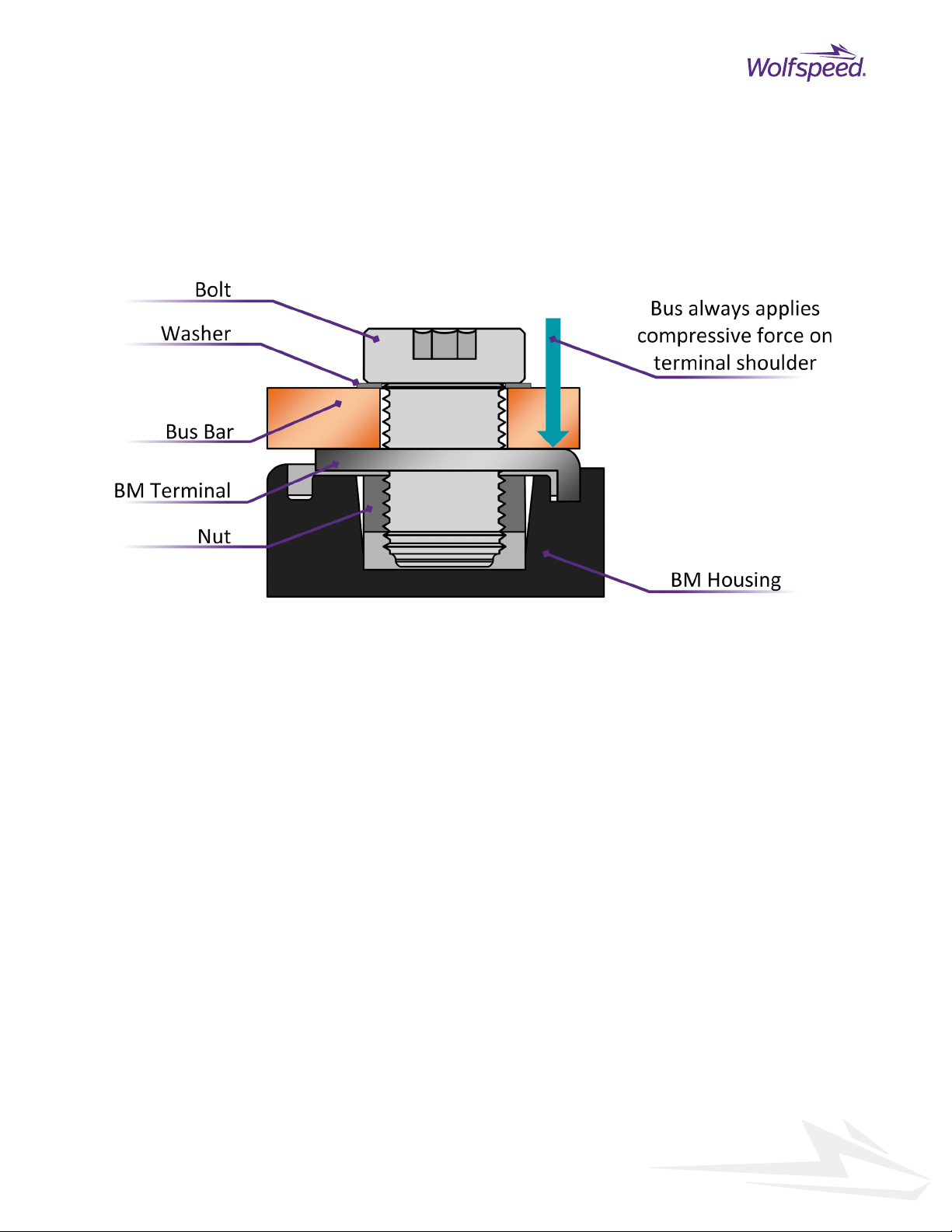
5.2 Power Terminal Vibrations
The power terminals are made of a copper conductor with a bolted interface. The module terminal is bent down
to trap a threaded nut that allows the bus to be bolted firmly to the terminal. This external power connection
can be a lug on the end of a cable but in most cases will be some form of laminated copper sheets or even thick
copper printed wiring board. This trapped nut and the bolt form a bolted interface requiring sufficient torque
to prevent an induced vibration from causing the interface to come apart.