manuals.online logo
Brands
  1. Home
  2. •
  3. Brands
  4. •
  5. Wolo
  6. •
  7. Air Compressor
  8. •
  9. Wolo 858 TORNADO User manual

Wolo 858 TORNADO User manual

Your purchase of a WOLO TORNADO Air Tank & Compressor is a perfect choice to power your high-pressure
air horns, tools and accessories. The Wolo name, with more than thirty years of experience, is your guarantee
of a superior horn product. If you need help installing this product, our technicians are available to answer your
questions, Monday through Friday from 9 AM to 4 PM EST by calling 1-888-550-HORN (4676).
IMPORTANT: The compressor comes pre-mounted
to the air storage tank. The installer has the option to
separate the compressor from the tank and mount it
independently.
INDEPENDENT COMPRESSOR / TANK MOUNTING
(Fig. 1):
1. If the method of mounting the compressor is to be
independent of the tank, remove the four screws that
secure the compressor to the tank, then disconnect
the braided hose from the tank. You will now be able
to separate the compressor from the tank.
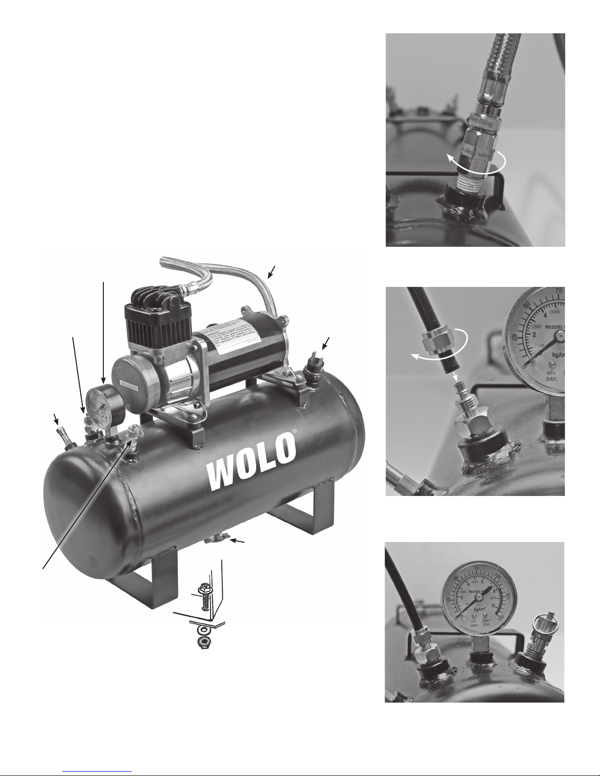
COMPRESSOR and TANK INSTALLATION (Fig. 2):
IMPORTANT! When selecting a mounting location for
the compressor, make sure that the compressor’s
braided hose will be close enough to the tank’s inlet
connection.
COMPRESSOR INSTALLATION (Fig. 2A):
2. Locate a convenient location to mount the
compressor that will be dry. If the location
is the engine compartment make sure
the compressor is safe from the heat of
the exhaust manifold and try to mount
compressor as far to the front of vehicle as
possible to provide optimum airow around
compressor. IMPORTANT! Do not mount
on a plastic fender well, or on exible
material.
3. Using the compressor’s mounting base as
a template, mark the hole locations and
drill to size, use a 3/16” drill bit. Secure the
compressor to the mounting surface using
the hardware provided. (Fig. 2A)
TANK INSTALLATION (Fig. 2B):
4. The mounting location for the tank should
be easily reachable so that the tank
can be periodically serviced, draining
condensation, water from the petcock
located on the bottom of the tank.
5. Use the tank’s mounting bracket as a
template, mark the hole locations and drill
to size 15/64”. Secure tank with hardware
provided.
Installation Instructions for
Model 858 TORNADO™AIR TANK & COMPRESSOR
Fig. 1
Fig. 2
Remove
the four
screws
Make sure
that the
locations
of the
compressor
and the tank
will be close
enough to
allow the
braided hose
to connect to
tank’s inlet
Tank’s
outlet
connection
Tank’s inlet
connection
Fig. 2B
Use the tank’s mounting base
as a template to mark the
15/64” holes for drilling
Fig. 2A
Use the compressor’s mounting
base as a template to mark the
3/16” holes for drilling
The braided
hose can be
disconnected
if it will aid in
the installation
HOSE INSTALLATION (Fig. 3 and Fig. 4):
6. If the compressor was separated from the tank, connect the
stainless steel braided hose from the compressor to tanks inlet
port. (Fig. 3.) IMPORTANT: Make sure the threaded tting
on the end of the braided hose has either been wrapped with
Teon®tape or coated with pipe sealant to prevent air leaks.
7. Using the high-pressure plastic hose provided, cut to size to
be able to connect the tank to inlet tting of the accessory or
valve requiring high-pressure air. Place the brass nut from the
tank’s outlet tting onto the high-pressure plastic hose. Push
the plastic hose fully onto the outlet tting, tighten the brass nut
onto the outlet tting. (Fig. 4 and 5)
CAUTION: Do not over tighten the brass nut.
8. The other end of the plastic hose is connected to the accessory
or valve requiring high-pressure air.
.
Fig. 3 Connecting the metal braided hose
Fig. 4 Connecting the high-pressure
plastic hose
Fig. 5 High-pressure plastic hose connected
Shown above: Compressor mounted on the tank
Turn
clockwise
Turn brass nut
clockwise
Petcock
should be easily
reachable so that
the tank can be
periodically serviced
Pressure
Switch
High-pressure
tank outlet
Pressure
Gauge
Schrader
Valve-
to connect
to 20’
coiled
hose
Braided
hose
Use the tank’s mounting base
as a template to mark the
15/64” holes for drilling
Pressure
relief
valve
WIRING COMPRESSOR
(Fig. 7 through Fig. 9):
9. The compressor’s red wire
is connected to a (+) 12-volt
power source, using the fuse
provided.
IMPORTANT! The fuse must
be connected directly to the
power source.
IMPORTANT! The red fused
wire must be connected to
a (+) 12-volt power source
controlled by the vehicle’s
ignition switch. This will
protect your compressor
from running continuously
and being damaged if an
air leak develops when the
vehicle is not in operation.
Suggested connection points
are: blower motor, windshield
wiper motor or the accessory terminal on the fuse panel. Make sure the
connection point has a wire that is as heavy as the compressor’s wires and
the connection point is capable of handling 25-amps. CAUTION: remove
the fuse from the fuse holder until installation is complete.
OPTIONAL: A switch can be installed into the compressor’s red wire. This will
permit the driver to turn-off the system if it is not required. (Fig. 7)
10. The compressor’s black wire is connected to a rubber plug. NOTE: the
rubber plug will have two black wires, both wires will connect to the tank’s
pressure switch.
IMPORTANT: It is recommended that both black wires be pushed forward
so that the terminals are extending out of the rubber boot exposing the 1/4”
female terminals (Fig. 8.).
11. Select one of the black wires with the 1/4” female terminal, connect the
terminal to the pressure switch. Repeat the procedure for the other black
wire. NOTE: There is no polarity, so either black wire can be connected to
either pressure switch terminal (Fig. 8).
12. Push the rubber boot onto the pressure switch (Fig. 9).
13. The black wire with the looped terminal is connected to ground; secure
the wire’s terminal to either the (-) side of vehicle’s battery or under any
metal body bolt. Make sure that the ground connection is free of rust and
paint. NOTE: The compressor is now ready to be used.Install the fuse
back into the fuse holder and the compressor will automatically start.
When the pressure drops below 80 PSI in the tank, the pressure switch
will automatically turn on the compressor. When the tank pressure is
approximately 120 PSI the compressor will automatically turn off. If the
compressor does not shut off after 4 minutes of running time, check all air
hose connections for leaks. Use soapy water or bubble solution on each tting, while the compressor is
pumping. Use a thread sealant if leak persists after tightening.
CAUTION: Do not touch compressor or ttings with bare hands during or immediately after usage, they
will be hot.
IMPORTANT! Compressor is equipped with an internal THERMAL OVERLOAD PROTECTOR. If compressor
should shut off before the tank has been lled to the pressure switch’s turn off pressure, do not attempt to
restart compressor. Allow compressor to cool off for approximately 40 minutes before resuming use.
Fig. 7
Fig. 8
Fig. 9
25 AMP
FUSE
Push both black wires
onto the pressure
switch terminals.
There is no
polarity, so either
black wire can
be connected to
either pressure
switch
terminal.
Push the rubber
boot down over
the pressure
switch
COMPRESSOR SPECIFICATIONS
12-Volt heavy-duty compressor
Current: 21 amps at peak
CFM: 2.55
In-line fuse holder with 25 amp fuse provided
Permanent magnetic motor that is gearless with thermo protection
Oil-less maintenance free design
High performance piston ring
Moisture & dust resistant
Painted aluminum alloy cylinder
Mounting base has rubber vibration bushings
Stainless steel braided hose with in-line check valve
Washable air lter
Size: L 10-1/4 in. x W 3-1/2 in. x H 6-1/2 in.
TANK SPECIFICATIONS
2.5-Gallon
Welded steel mounting brackets
Petcock water drain
Pressure switch 80 psi. auto-on / 120 psi. off
Safety pressure relief valve rated at 150 psi.
Pressure gauge
Fitting all brass
Size: L 17-1/4 in. x W 6-1/2 in. x H 15-1/4 in. Compressor mount on tank
Size: L 17-1/4 in. x W 6-1/2 in. x H 8-1/4 in. Tank only.
ANY EXPRESSED WARRANTY NOT PROVIDED HEREIN IS EXCLUDED AND DISCLAIMED. THE IMPLIED
WARRANTIES OF MERCHANTABILITY AND OF FITNESS FOR A PARTICULAR PURPOSE ARE EXPRESSLY LIMITED
TO A TERM OF THREE (3) MONTHS. UNDER NO CIRCUMSTANCES SHALL WOLO BE LIABLE TO PURCHASER OR
ANY OTHER PERSON FOR ANY SPECIAL OR CONSEQUENTIAL DAMAGES, WHETHER ARISING OUT OF BREACH
OF WARRANTY OR OTHERWISE.
To obtain warranty service, return the product prepaid, and include the original bill of sale showing the date of purchase.
Provide with the return a brief description of the problem. Also, include with the return a check or money order in the amount
of $20.00 to cover return shipping. Mail to:
Wolo Manufacturing Corp. One Saxwood Street, Deer Park, NY 11729
Attn: Warranty Service E-mail: [email protected]
Warranty
Wolo Manufacturing Corporation (“Wolo”) warranties to the original purchaser, for three months from the
date of purchase, that this product is free from defects in workmanship and materials. If there is such a
proven defect, Wolo, at its option, will either repair or replace the item free of charge, if it is returned to Wolo
within three months from the date of purchase together with proof of purchase as described below. Wolo
reserves the right to inspect any defect prior to settling any warranty claim by repair or replacement. This
warranty is limited as above provided and Wolo will not be responsible for re or other casualty or accident,
due to neglect, abuse, abnormal use, modications, faulty installation of this product, or natural causes.
© 2014 Wolo Mfg. Corp. All Rights Reserved.

Other Wolo Air Compressor manuals

Wolo SHERMAN TANK AIR COMPRESSOR 830 User manual

Wolo

Wolo SHERMAN TANK AIR COMPRESSOR 830 User manual

Popular Air Compressor manuals by other brands

BE AC153 Operation manual

BE

BE AC153 Operation manual

RIDGID OF25150A Operator's manual

RIDGID

RIDGID OF25150A Operator's manual

Industrial Air CP1580325 Operator's & parts manual

Industrial Air

Industrial Air CP1580325 Operator's & parts manual

Bitzer CSH6553-35Y operating instructions

Bitzer

Bitzer CSH6553-35Y operating instructions

Sperre HV2/210 instruction manual

Sperre

Sperre HV2/210 instruction manual

Clarke RAIDER 15/1000 Operation & maintenance instructions

Clarke

Clarke RAIDER 15/1000 Operation & maintenance instructions

MAT Industries Airlink manual

MAT Industries

MAT Industries Airlink manual

Airpress LMO 5-240 user manual

Airpress

Airpress LMO 5-240 user manual

Grizzly G0954 owner's manual

Grizzly

Grizzly G0954 owner's manual

METZGER Technik DELTA 2 Series Technical manual

METZGER Technik

METZGER Technik DELTA 2 Series Technical manual

VONROC CR505DC Original instructions

VONROC

VONROC CR505DC Original instructions

DeWalt D55154 instruction manual

DeWalt

DeWalt D55154 instruction manual

ABB VTR Series Assembly instructions

ABB

ABB VTR Series Assembly instructions

Gardner Denver AirSmart VS80-110B Operating and service manual

Gardner Denver

Gardner Denver AirSmart VS80-110B Operating and service manual

NorthStar 25654 owner's manual

NorthStar

NorthStar 25654 owner's manual

Conrad 85 66 48 operating instructions

Conrad

Conrad 85 66 48 operating instructions

BLACKMER LB942A Installation, operation and maintenance instructions

BLACKMER

BLACKMER LB942A Installation, operation and maintenance instructions

Powermate 200-2706 E103520 Operator's & parts manual

Powermate

Powermate 200-2706 E103520 Operator's & parts manual

manuals.online logo
manuals.online logoBrands
  • About & Mission
  • Contact us
  • Privacy Policy
  • Terms and Conditions

Copyright 2025 Manuals.Online. All Rights Reserved.