Wolo OCEAN ALERT 160-24 User manual

Your purchase of a Wolo OCEAN ALERT®Air Horn will complement your boat while offering an extra
level of protection. Wolo’s products are manufactured with the finest materials. Each horn is tested to ensure
it meets all of our manufacturing specifications, before being packaged. If you need help installing your new
Wolo horn, our technicians are available to answer your questions, Monday thru Friday, 9 AM to 4 PM EST
at 1-888-550-HORN (4676).
Before installation of the horn is attempted, it is important to read these instructions completely. The lives of
people can be dependent on a proper installation of the horn. The person doing the installation must have
knowledge of the proper method for mounting and securing the horn to the exterior of the boat as well as
knowledge of the boat’s electrical system. Again, read the instructions completely and note any messages
marked “IMPORTANT” or “WARNING’’. A safe installation will prevent injury or damage to the boat.
WARNING: Installation of the OCEAN ALERT requires drilling. The installer must carefully inspect both sides
of the selected mounting locations to ensure that there are no wires, fuel line and or any other components that
could be damaged by drilling.
WARNING: If any wires are routed through drilled holes; always de-burr ensuring that there are no sharp
edges. Install a rubber grommet into all metal holes that wires are being routed through.
MOUNTING TRUMPET: Fig. 1
IMPORTANT: The horn should be mounted
facing forward whenever possible. The NMMA
Certification Program requires this for boats 39’
or longer.
1. Locate the desired mounting location of the
trumpet. For best results, the front of the horn
should be unobstructed so that the sound can
carry straight ahead.
IMPORTANT: FOR BEST PERFORMANCE
AND SOUND, ALWAYS MOUNT THE
COMPRESSOR CLOSE TO TRUMPET,
KEEPING THE HOSE LENGTH AS SHORT
AS POSSIBLE. THE COMPRESSOR
MUST BE MOUNTED IN A DRY INTERIOR
LOCATION).
2. Use the horn’s gasket as a template, mark
hole locations and drill to size.
3. Thread the two chrome air inlet tubes into the base of the horn.
4. Mount and secure the horn as shown in Fig. 1.
IMPORTANT: Be sure to use the rubber gasket provided to protect against water leaks. Tighten the base plate
nuts that thread onto air inlet tubes evenly to ensure a watertight seal.
INSTALLATION INSTRUCTIONS
Model 160-24 OCEAN ALERT®MINI
24-Volt
air
inlet
tubes

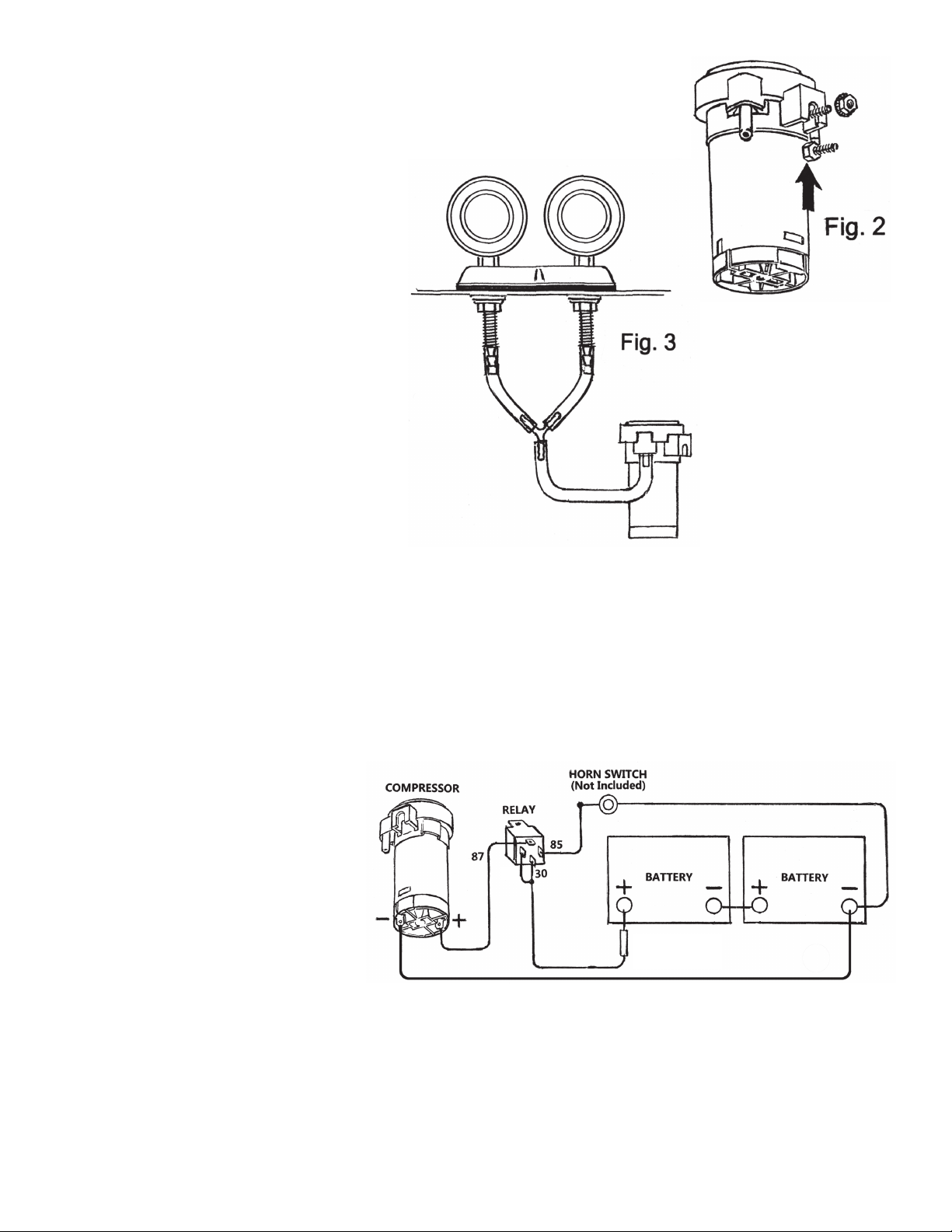
COMPRESSOR INSTALLATION: Fig. 2 & 3
5. Install the compressor in a dry interior location.
IMPORTANT: The compressor should not be mounted further than 30 inches
from the trumpet to ensure best sound.
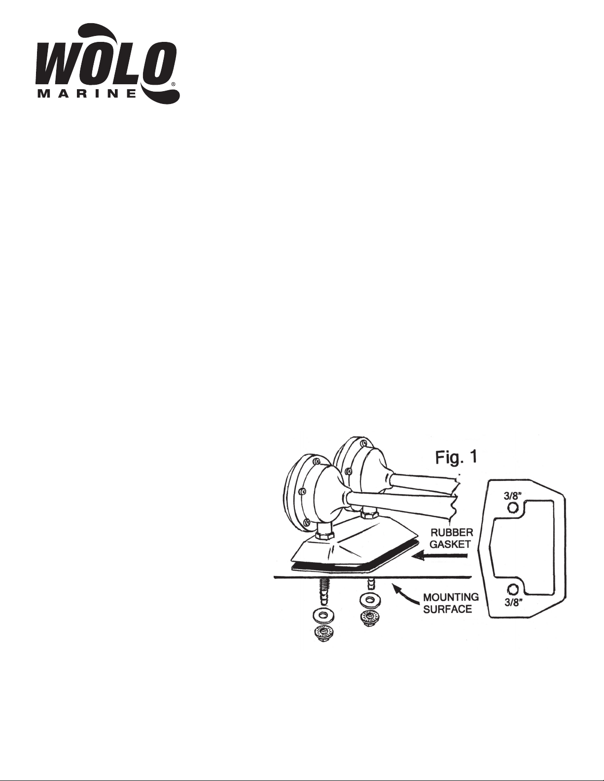
6. To secure the compressor, drill one
3/16” hole. When possible, mount the
compressor vertically (air outlet on top).
Install the head of the bolt into the slot
on the side of the compressor. Secure
the compressor using the lock washer/
nut provided as shown in Fig. 2.
7. Using the plastic tubing provided, cut
to size and connect the compressor to
the horn’s two air inlets using the “Y”
connector provided as shown in Fig. 3.
WARNING: Avoid making any kinks
or sharp bends in plastic tubing that
can reduce air flow and alter the horn’s
sound. For best performance and sound
always keep the plastic tubing as short
as possible
WIRING:
ELECTRICAL CONNECTIONS FOR USING A NEW HORN BUTTON SWITCH Fig. 4
8. Install the horn relay provided, locate close to the compressor in a dry interior location with the terminals
facing downward.
9. Connect relay terminal 87 to the compressor’s positive (+) terminal. Use 16-gauge wire or heavier.
10. Connect relay terminal 85 to the horn button switch terminal. (Horn switch not provided).
11. The horn switch’s other terminal
is connected to negative (-) such as
the (-) battery post or any clean metal
negative surface. Use 18 gauge wire or
heavier.
12. Connect relay terminal 30 &
86 to positive (+) 24-volts such as
battery, alternator, fuse block or
etc., using 16-gauge wire or heavier.
IMPORTANT: Protect the electrical
circuit with the fifteen (15)-amp inline
fuse provided. WARNING: The inline
fuse must be connected directly to the
power source.
13. Connect the compressor’s negative
(-) terminal to boat’s battery, (-) post or
any clean metal negative surface. Use not less than 16-gauge wire.
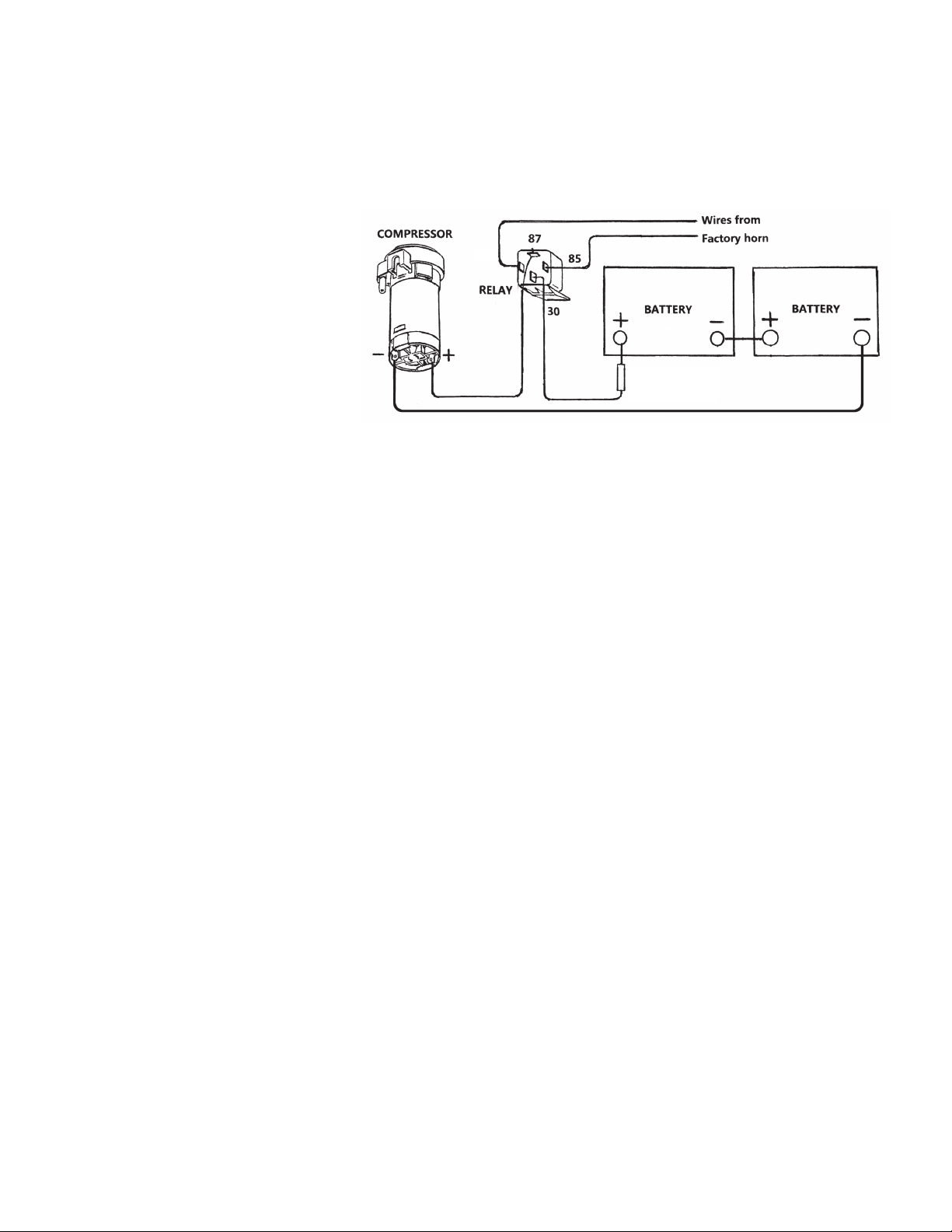
RECAP OF RELAY TERMINAL CONNECTIONS:
Relay terminals 30 & 86: the two terminals are connected to 24-volts (+) positive, using the 15-amp inline fuse.
Relay terminal 85: is connected to horn switch.
The horn switch’s other terminal: is connected to negative (-) battery post.
Relay terminal 87: is connected to the compressor’s (+) motor terminal.
The compressor’s negative (-) terminal is connected the boat’s negative (-) battery post.
air
inlet
tubes
Fig. 4
86
15 AMP
FUSE

WIRING:
USING BOATS FACTORY HORN SYSTEM (TWO WIRE SYSTEM) Fig. 5
WARNING: You are required to use the relay supplied with this horn kit to protect the factory horn button switch
and wiring. The original factory horn draws less amperage. The relay will ensure that the horn works reliably
and will protect the factory horn system.
14. Remove the two (2) wires
connected to factory horn.
15. Connect relay terminal 85 to one of
the factory horn wires. Note: It does not
make a difference which factory horn
wire is connected to terminal 85.
16. Connect relay terminal 86 to the
other factory horn wire.
17. Connect relay terminal 30 to
positive (+) 24-volts such as the battery,
alternator or fuse block, using 16-gauge
or heavier wire. WARNING: The 15-
amp inline fuse provided must be
connected directly to the power source.
18. Connect relay terminal 87 to the compressor’s positive (+) terminal. Use not less than 16-gauge wire.
19. Connect the compressor’s negative (-) terminal to boat’s negative (-) battery post or any clean metal
negative surface. Use not less than 16-gauge wire.
RECAP OF RELAY TERMINAL CONNECTIONS
Relay terminals 30: connected to 24-volts (+) positive, using the 15-amp inline fuse.
Relay terminal 85: is connected to one of the factory horn wires.
Relay terminal 86: is connected to the other factory horn wire.
Relay terminal 87: is connected to the compressor’s (+) motor terminal.
The compressor’s negative (-) terminal: is connected the boat’s negative (-) battery post.
WARNING: ALWAYS TEST THE HORN SIGNAL SYSTEM BEFORE USING THE VESSEL SO TO ENSURE
THE HORN IS FUNCTIONING AT PEAK PERFORMANCE. YOU’RE LIFE AND THE LIVES OF PEOPLE
ARE DEPENDENT ON THE VESSEL HAVING A WORKING HORN SIGNAL SYSTEM. NEVER USE THE
VESSEL WITHOUT A WORKING HORN SYSTEM.
Fig. 5
86
15 AMP
FUSE

ANY EXPRESSED WARRANTY NOT PROVIDED HEREIN IS EXCLUDED AND DISCLAIMED.
THE IMPLIED WARRANTIES OF MERCHANTABILITY AND OF FITNESS FOR A PARTICULAR
PURPOSE ARE EXPRESSLY LIMITED TO A TERM OF TWELVE (12) MONTHS. UNDER NO
CIRCUMSTANCES SHALL WOLO BE LIABLE TO PURCHASER OR ANY OTHER PERSON FOR
ANY SPECIAL OR CONSEQUENTIAL DAMAGES, WHETHER ARISING OUT OF BREACH OF
WARRANTY OR OTHERWISE.
To obtain warranty service, return the product prepaid, and include the original bill of sale showing the
date of purchase. Provide with the return a brief description of the problem. Also, include with the return
a check or money order in the amount of $10.00 to cover return shipping. Mail to:
Wolo Manufacturing Corp.
One Saxwood Street, Deer Park, NY 11729
Attn: Warranty Service
E-mail: [email protected]
WARRANTY
Wolo Manufacturing Corporation (“Wolo”) warranties to the original purchaser, for twelve months
from the date of purchase, that this product is free from defects in workmanship and materials.
If there is such a proven defect, Wolo, at its option, will either repair or replace the item free of
charge, if it is returned to Wolo within twelve months from the date of purchase together with proof
of purchase as described below. Wolo reserves the right to inspect any defect prior to settling any
warranty claim by repair or replacement. This warranty is limited as above provided and Wolo will
not be responsible for fire or other casualty or accident, due to neglect, abuse, abnormal use,
modifications, faulty installation of this product, or natural causes.
© 2013 Wolo Mfg. Corp All Rights Reserved.
This horn meets the following standards:
Meets the U.S.
Coast Guard’s
C.O.L.R.E.G.S. and
U.S. Inland Navigation
Rules, Annex III
Regulations for boats
up to 20 meters / 65 ft.
This horn is National
Marine Manufacturers
Association (NMMA)
“type accepted”
Meets the American Boat
& Yacht Council (ABYC)
A-23 standard for boats
up to 20 meters / 65 ft.
Table of contents
Other Wolo Horn manuals

Wolo
Wolo OCEAN ALERT 170 User manual

Wolo
Wolo 320-2T User manual

Wolo
Wolo EE100 User manual

Wolo
Wolo SEA SAFE 135 User manual

Wolo
Wolo OCEAN ALERT 160 User manual

Wolo
Wolo 357 SERIES User manual

Wolo
Wolo HIDEAWAY BLAST 900 User manual

Wolo
Wolo 94117 User manual

Wolo
Wolo OCEAN ALERT 170-24 User manual

Wolo
Wolo 418-24 User manual
Popular Horn manuals by other brands

Vixen Horns
Vixen Horns VXO8330/1264Y installation guide

Altec Lansing
Altec Lansing HF HORNS MULTICELLULAR HORNS manual

Federal Signal Corporation
Federal Signal Corporation 31X Series Installation and service instructions

Pyle
Pyle PMP59iR quick start guide

BERG
BERG Sound box user manual

Vixen Horns
Vixen Horns VXO8815/4114 installation guide