wolter RF Operating and maintenance manual

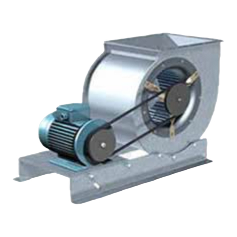
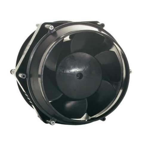
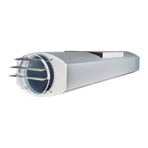
Model: EKN, EKNS, DKN, DKNS
Maintenance
and
Operating Instructions
English Version
Contents Page
Safety 1
Description 1
Condition of use 1
Storage, transport 1
Installation 1
Operation 2
Maintenance 2
Repair 3
Service, address of producer 3
Appendix: weight chart 3
This operation instruction contains important technical advice and
information about safety.
Therefore please pay attention to this operation instruction before
unpacking, installation or
any other work is undertaken on this fan!
Model: RF, EKN, EKNS, DKN, DKNS
Maintenance
and
Operating Instructions
(English Version)

1. SAFETY
The following symbols refer to
particular dangers or give advice for save
operation
Danger
Danger from electric current / high voltage!
Danger! Do not step under hanging load!
Crush danger!
Important, information
Safety advice
Wolter In line ducts are produced in
accordance with the latest technical standards
and our quality assurance programme, which
includes material and function tests, ensures
that the final product is of a high quality and
durability. Never the less these fans can be
dangerous if they are not used and installed
correctly, according to the instructions
Before installing and operating this fan
please read instructions carefully!
Only use the fan after it has been securely
mounted and fitted with protection guards and
maintenance cover to suit the application
(Tested guards can be supplied for all fans
from our programme). Installation, electrical
and mechanical maintenance and service
should only be undertaken by qualified worker!
The fan must only be used according to its
design parameters, with regard to required
performance stated in the name-plate and
mediums passing through it!
2. DESCRIPTION
Duct fans were especially developed for use in
modern ventilation systems. By using external
rotor motors there are significant technical
advantages in operation. All duct fans are 100%
speed controllable and are statically and
dynamically balanced as a composite unit in
our factory. The fans are also available with
motor/impellers to be folded out for
maintanence
3. CONDITIONSOFUSE
Duct fans can be used for ventilation of:
•Clean air
•Slightly dusty and greasy air
•Slightly aggressive gases and fumes
(please refer to our engineers)
•mediums up to an atmosheric density of
1,2 kg/m3
•Mediums passing through with a
temperature of -30°C up to + 40°C
•Mediums up to a max. Humidity of 95%
4. STORAGE & TRANSPORT
•Store the fan on a dry place and weather
protected in its original packing
•Cover open palettes with a tarpaulin and protect
the fans against influence of dirt (i.e. Stones,
splinters, wires, etc.).
•Storage temperatures between -30°C and +
40°C
•With storage times of more than 1 year, please
check the bearings on soft running before
mounting (turn by hand).
•Transport the fan with suitable loading means:.
•Do not damage casing.
•Use suitable assembling means as e.g. scaffolds
conforming to specifications.
Danger! Do not step under hanging load!
5. INSTALLATION
Installation and electric work only by skilled
and introduced workers and in accordance to
applying regulations!
Installation of fan either with mounting flange directly to
the duct system, possibly by conjunctions with a sound
attenuator or, in order to avoid noise transmission, with
flexible connectors, installed on the inlet and outlet.
The standard method of mounting is via a pre-prepared
platform or for vertical mounting channel section
brackets fixed to the fan casing. (8" weight as per chart
in enclosure
For installation on mounting flange use M8 screws and
secure properly
Avoidsoundbridges byuse ofisolation
material (i.e. sponge rubber)
Check impeller rotation by hand for soft running
For external mounting weather protection should be
used.This should be designed to suit the installation
and is supplied by others.
The duct system must not be supported by
the fan casing !

Electric wiring must be in accordance with
technical connection regulations and local
ordinances and national electric codes as per
enclosed wiring diagram in the terminal box or
on the casing.
•If the junction box is to be fitted to the
fan casing, the holes for fixing (0 2,5
mm) must be drilled outside the impeller
rotation area.
•Fix the junction box with screws (max. dia
of 4 mm) to fan casing.
•Insert cable according to the instructions
in the junction box and seal it.
•Connect thermal contacts for motor
protection according to the instructions-
otherwise the guarantee is invalid.
Connect electric supply.
Do not use metal compression-gland fittings
with plastic terminal boxes!
Before control of direction of rotation:
•Remove any foreign matter from the
fan.
•Install protection guards or give no
entry to fan.
•Check direction of rotation as per
direction arrow on the casing by short
turning on.
•with 3-phase-motor
-change of direction of rotation possibly
by change of two phases!
•with 1-phase-motor
-change direction of rotation if necessary
with changing of Z1 (black) and Z2
(orange)
-change of current direction in secondary
winding.)
Crush danger! Do not reach into rotating
impeller!
•Close maintenance cover (if any)
6. OPERATION
Prepare fan for first operation
•Correct mechanical installation
•Electrical installation in accordance with
regulations
•Remove foreign matter from inlet and
outlet area and from inside of fan
•Protection guard installed, maintenance
cover closed, no entry to fan or fan being
installed out of arm sweep.
Only commence operation when it is in
stalled in accordance with ordinances!
If the fan is started under free blow conditions,
i.e. prior to connecting to ducting system, the
current consumption may exceed the normal
maximum (forbidden area of performance curve)!
The terminal protection of the motor may
activate!
Taking fan in operation
•Observe correct function (smoothness of
running, vibration, unbalance current
consumption,possibly controllability)
By regular inspection of the fan inlet make
sure debris has not collected on the guard
and clean if necessary!!
7. Maintenance
Our fans are maintenance free with
normal operation! When using them in the
fringe range simple maintenance work may
be required!
Before any maintenance work is undertaken:
Stop fan in accordance to regulations and
disconnect all poles from mains supply.
•Wait until impeller is stationary!
•Make sure that is restart is not
possible!
Clean fan
•Clean impeller
•Keep the motor dry!
•Do not damage impeller, blades!
Only use usual commercial cleaning
material paying attention to the
prescribed safety measures and do
not use any abrasive tools (surface
protection will be destroyed!)
General controls
•Bearing play too large?
•Grease leaking on bearings?
•Surface protection affected by medium to
be ventilated too aggressive?
•Unusual operation noise?
•Fan capacity for possibly exceeded duct
system still sufficient causing
overloading?

8. REPAIR
Before any repairs are undertaken
Please:
Stop fan in accordance to regulations
and disconnect all poles form mains
supply. Wait until impeller is
stationary!
Make sure that is restart is not possible!
Only use original spare parts manufactured
and supplied by Wolter!
Change of motor impeller
•Disconnect electrical supply in junction
box
•Unscrew motor mounting and pull out of
the casing complete with motor impeller
•Install a new motor impeller complete
with motor mounting in casing
•Connect electric supply
Control whether installation is correct
•motor impeller must rotate freely
•control whether direction of rotation is
correct !
•Install maintenance cover if any
10. APPENDIX: WEIGHT CHART
Three Phase - DKN/DKNS - 400V/50Hz
Approx.
Type C400V uF Kg Wire Connection
400-4 65 DS1
355-4 58 DDO
400-6 76 DS1
315-4 35 DDO
315-4 Ex stb 35 DD1
280-4 22 DDO
280-4 Ex stb 24 DD1
250-4 17 DS1
250-4 Ex stb 17 DS3
225-4 12 DS1
225-4 Ex stb 14 DS3
200-4 10 DS1
355-6 43 DDO
355-6 Ex stb 40 DD1
400-8 63 DS1
315-6 26 DDO
280-6 20 DS1
450-6 80 DS1
9. SERVICE, ADDRESS OF PRODUCTER
Wolter products are subject to steady quality
controls and are in accordance with valid
regulations. In case you have any questions with
regard to our products please contact either your
local agent of your air handling unit or directly to one
of our distributors or:
Wolter GmbH Co Kg
Am Wasen 11,
D-76316 Malsch
Tel: 49-7204 9210,
Telefax: 49-7204 920111
Please contact your local Sale & Support Service at:
Single Phase - EKN/EKNS - 230V/50Hz
Approx.
Type C400V uF Kg Wire Connection
280-4 16 12,5 E12
250-4 14 22 E12
225-4 8 14 E12
200-4 8 10 E12
315-6 10 29 E12
280-6 10 24 E12
250-6 6 22 E12
200-2 4 10 E11
Single Phase - RF, EKN/EKNS - 230V/50Hz
RF 150-4 2 5,4 E16-3
This manual suits for next models
4
Other wolter Fan manuals