Wood Bros 3200NT User manual

3200NT Timer
Service Manual
Valve Serial Number
Valve Position 1-LEAd 2-LAg 3-LAg 4-LAg
41151
NT001-1
IMPORTANT: Fill in pertinent information on
page 3
for future reference.

3200NT Timer
Table of Conte nts
Job Specifications Sheet . . . . . . . . . . . . . . . . . . . . . . . . . . . . . . . . . . . . . . . . . . . . . . . . . . . . . . . . . . . . . . . . . . . . . 3
Timer Operation . . . . . . . . . . . . . . . . . . . . . . . . . . . . . . . . . . . . . . . . . . . . . . . . . . . . . . . . . . . . . . . . . . . . . . . . . . . . 4
Set Time of Day . . . . . . . . . . . . . . . . . . . . . . . . . . . . . . . . . . . . . . . . . . . . . . . . . . . . . . . . . . . . . . . . . . . . . . . . . 4
Manually Initiating a Regeneration . . . . . . . . . . . . . . . . . . . . . . . . . . . . . . . . . . . . . . . . . . . . . . . . . . . . . . . . . . 4
Timer Operation During Regeneration . . . . . . . . . . . . . . . . . . . . . . . . . . . . . . . . . . . . . . . . . . . . . . . . . . . . . . . 4
Start a Regeneration Tonight . . . . . . . . . . . . . . . . . . . . . . . . . . . . . . . . . . . . . . . . . . . . . . . . . . . . . . . . . . . . . . 4
Day Regeneration Timer . . . . . . . . . . . . . . . . . . . . . . . . . . . . . . . . . . . . . . . . . . . . . . . . . . . . . . . . . . . . . . . . . . 4
Flow Meter Equipped Timer . . . . . . . . . . . . . . . . . . . . . . . . . . . . . . . . . . . . . . . . . . . . . . . . . . . . . . . . . . . . . . . 4
Timer Operation . . . . . . . . . . . . . . . . . . . . . . . . . . . . . . . . . . . . . . . . . . . . . . . . . . . . . . . . . . . . . . . . . . . . . . . . . . . . 5
Immediate Regeneration Timer with Regeneration Day Override Set . . . . . . . . . . . . . . . . . . . . . . . . . . . . . . . 5
Delayed Regeneration Timer with Regeneration Day Override Set . . . . . . . . . . . . . . . . . . . . . . . . . . . . . . . . .5
Timer Operation During Programming . . . . . . . . . . . . . . . . . . . . . . . . . . . . . . . . . . . . . . . . . . . . . . . . . . . . . . . 5
Timer Operation During A Power Failure . . . . . . . . . . . . . . . . . . . . . . . . . . . . . . . . . . . . . . . . . . . . . . . . . . . . . 5
Remote Lockout . . . . . . . . . . . . . . . . . . . . . . . . . . . . . . . . . . . . . . . . . . . . . . . . . . . . . . . . . . . . . . . . . . . . . . . . 5
Remote Signal Start Regeneration . . . . . . . . . . . . . . . . . . . . . . . . . . . . . . . . . . . . . . . . . . . . . . . . . . . . . . . . . . 5
Day Override Feature . . . . . . . . . . . . . . . . . . . . . . . . . . . . . . . . . . . . . . . . . . . . . . . . . . . . . . . . . . . . . . . . . . . . 5
System Operations . . . . . . . . . . . . . . . . . . . . . . . . . . . . . . . . . . . . . . . . . . . . . . . . . . . . . . . . . . . . . . . . . . . . . . . . . 6
System 4 . . . . . . . . . . . . . . . . . . . . . . . . . . . . . . . . . . . . . . . . . . . . . . . . . . . . . . . . . . . . . . . . . . . . . . . . . . . . . . 6
System 5 . . . . . . . . . . . . . . . . . . . . . . . . . . . . . . . . . . . . . . . . . . . . . . . . . . . . . . . . . . . . . . . . . . . . . . . . . . . . . . 6
System 6 . . . . . . . . . . . . . . . . . . . . . . . . . . . . . . . . . . . . . . . . . . . . . . . . . . . . . . . . . . . . . . . . . . . . . . . . . . . . . . 6
System Operations . . . . . . . . . . . . . . . . . . . . . . . . . . . . . . . . . . . . . . . . . . . . . . . . . . . . . . . . . . . . . . . . . . . . . . . . . 7
System 7 . . . . . . . . . . . . . . . . . . . . . . . . . . . . . . . . . . . . . . . . . . . . . . . . . . . . . . . . . . . . . . . . . . . . . . . . . . . . . . 7
System 9 . . . . . . . . . . . . . . . . . . . . . . . . . . . . . . . . . . . . . . . . . . . . . . . . . . . . . . . . . . . . . . . . . . . . . . . . . . . . . . 7
Important System Operations Tips . . . . . . . . . . . . . . . . . . . . . . . . . . . . . . . . . . . . . . . . . . . . . . . . . . . . . . . . . . 7
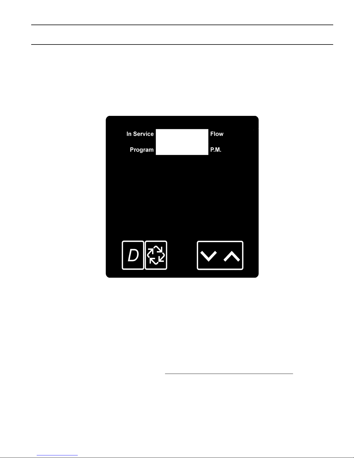
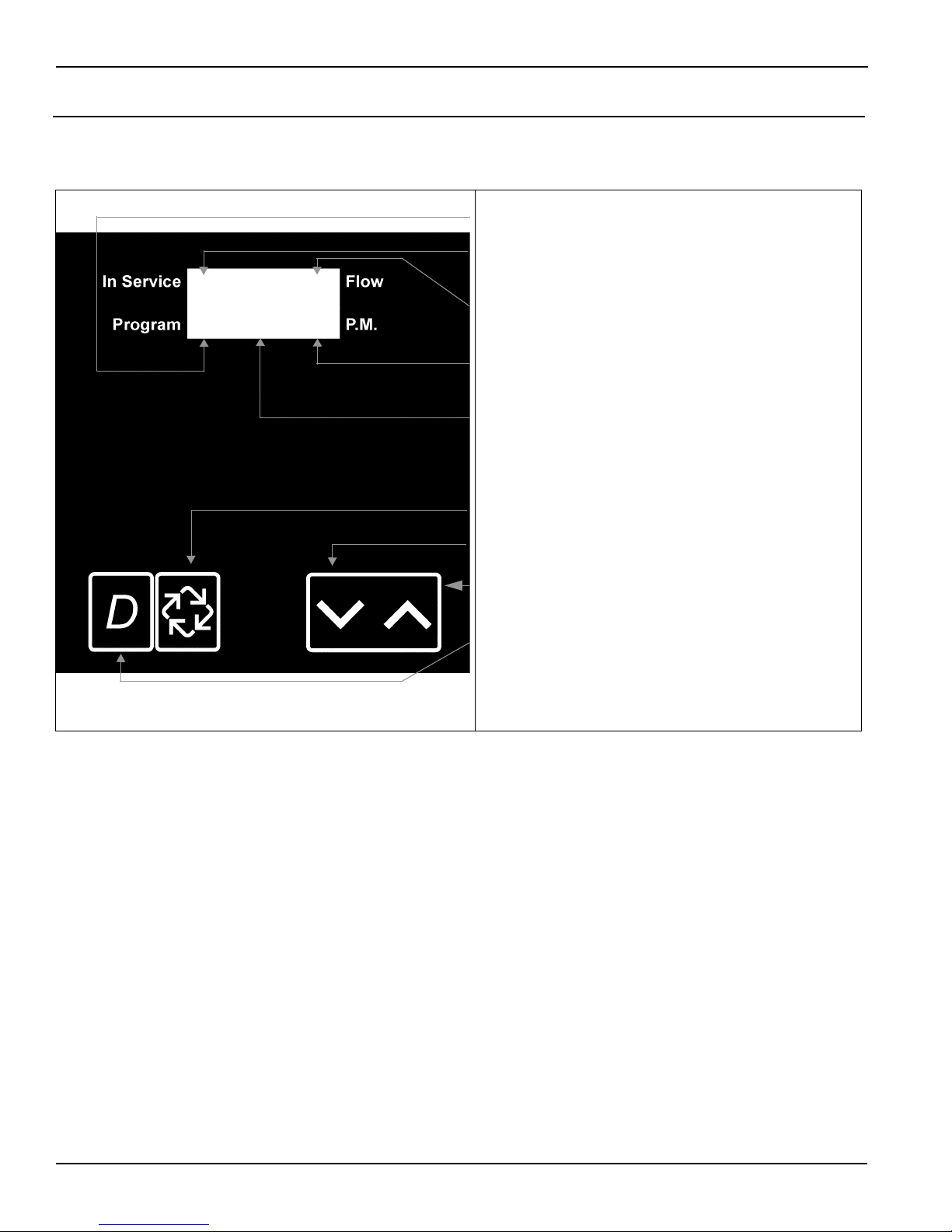
Timer Displays . . . . . . . . . . . . . . . . . . . . . . . . . . . . . . . . . . . . . . . . . . . . . . . . . . . . . . . . . . . . . . . . . . . . . . . . . . . . . 8
Timer Display Description . . . . . . . . . . . . . . . . . . . . . . . . . . . . . . . . . . . . . . . . . . . . . . . . . . . . . . . . . . . . . . . . . 8
Timer Programming Mode . . . . . . . . . . . . . . . . . . . . . . . . . . . . . . . . . . . . . . . . . . . . . . . . . . . . . . . . . . . . . . . . . . . . 9
Timer Operation Display Definitions and Examples . . . . . . . . . . . . . . . . . . . . . . . . . . . . . . . . . . . . . . . . . . . . . . . . 10
Timer Diagnostics Display Definitions and Examples . . . . . . . . . . . . . . . . . . . . . . . . . . . . . . . . . . . . . . . . . . . . . . 11
Power Head Assembly Parts List
2750/2850/2900 Upper Drive and 2900 Lower Drive . . . . . . . . . . . . . . . . . . . . . . . . . . . . . . . . . . . . . . . . . . . . . . . 13
Power Head Assembly,
3150/3900 Upper Drive and 3900 Lower Drive . . . . . . . . . . . . . . . . . . . . . . . . . . . . . . . . . . . . . . . . . . . . . . . . . . . 14
Power Head Assembly Parts List,
3150/3900 Upper Drive and 3900 Lower Drive . . . . . . . . . . . . . . . . . . . . . . . . . . . . . . . . . . . . . . . . . . . . . . . . . . . 15
2750/2850 Timer Wiring Diagram . . . . . . . . . . . . . . . . . . . . . . . . . . . . . . . . . . . . . . . . . . . . . . . . . . . . . . . . . . . . . 16
3150 Timer Wiring Diagram . . . . . . . . . . . . . . . . . . . . . . . . . . . . . . . . . . . . . . . . . . . . . . . . . . . . . . . . . . . . . . . . . 17
2900 Timer Wiring Diagram . . . . . . . . . . . . . . . . . . . . . . . . . . . . . . . . . . . . . . . . . . . . . . . . . . . . . . . . . . . . . . . . . . 18
3900 Timer Wiring Diagram . . . . . . . . . . . . . . . . . . . . . . . . . . . . . . . . . . . . . . . . . . . . . . . . . . . . . . . . . . . . . . . . . . 19
Network Timer System Configuration Wiring Diagrams . . . . . . . . . . . . . . . . . . . . . . . . . . . . . . . . . . . . . . . . . . . . . 20
Interlocking 3200NT . . . . . . . . . . . . . . . . . . . . . . . . . . . . . . . . . . . . . . . . . . . . . . . . . . . . . . . . . . . . . . . . . . . . 20
Installing and Grounding the Transformer . . . . . . . . . . . . . . . . . . . . . . . . . . . . . . . . . . . . . . . . . . . . . . . . . . . . 21
Troubleshooting . . . . . . . . . . . . . . . . . . . . . . . . . . . . . . . . . . . . . . . . . . . . . . . . . . . . . . . . . . . . . . . . . . . . . . . . . . . 22
Communication Error . . . . . . . . . . . . . . . . . . . . . . . . . . . . . . . . . . . . . . . . . . . . . . . . . . . . . . . . . . . . . . . . . . . 22
Troubleshooting . . . . . . . . . . . . . . . . . . . . . . . . . . . . . . . . . . . . . . . . . . . . . . . . . . . . . . . . . . . . . . . . . . . . . . . . . . . 23
Programming Error . . . . . . . . . . . . . . . . . . . . . . . . . . . . . . . . . . . . . . . . . . . . . . . . . . . . . . . . . . . . . . . . . . . . . 23
Simultaneous Communication and Programming Errors . . . . . . . . . . . . . . . . . . . . . . . . . . . . . . . . . . . . . . . . 23
IMPORTANT: The information, specifications and illustrations in this manual are based on the latest information
available at the time of printing. The manufacturer reserves the right to make changes at any time without notice.

3200NT Timer
3
Job Specifications Sheet
Please circle and/or fill in the appropriate data for future reference.
Programming Mode:
Feed Water Hardness _______ Grains Per Gallon or _______ Degrees
Regeneration Time: Delayed_______a.m. / p.m. or Immediate
Regeneration Day Override Off or Every _______ Days
Master Programming Mode:
Valve Model
2750 2850 2900 3150 3900
Regeneration Type Downflow Upflow Brine Draw First Upflow Brine Fill First
System Type 4 Time Clock 4 Meter Immediate 4 Meter Delayed
5 Interlock 6 Series 7 Alternating 9 Alternating
Valve Position LEAd or LAg
Remote Signal Start Off or On Signal Time needed _______ Minutes
Display Format US Gallons or m3
Unit Capacity _______________ Grains or Degrees
Capacity Safety Factor Zero or ____%
Regeneration Cycle Step #1 ____ Minutes
Regeneration Cycle Step #2 Off or ____ Minutes
Regeneration Cycle Step #3 Off or ____ Minutes
Regeneration Cycle Step #4 Off or ____ Minutes
Regeneration Cycle Step #5 Off or ____ Minutes
Time Auxiliary Relay Output
Window #1 Off or Start Time _________
End Time _________
Time Auxiliary Relay Output
Window #2 Off or Volume _________
Seconds _________
Fleck Flow Meter size 1” 1.25” 1.5” 2” 3” or Non Fleck ______ Pulses
Line Frequency 50Hz or 60Hz

3200NT Timer
4
Timer Operation
Set Time of Day
When the timer is In Service, push either the Set Up or Set Down button once to adjust the Time of Day by
one digit. Push and hold to adjust by several digits.
Manually Initiating a Regeneration
1. When timer is In Service, press the Extra Cycle button for 5 seconds to force a manual regeneration.
2. The timer reaches Regeneration Cycle Step #1.
3. Press the Extra Cycle button once to advance valve to Regeneration Cycle Step #2 (if active).
4. Press the Extra Cycle button once to advance valve to Regeneration Cycle Step #3 (if active).
5. Press the Extra Cycle button once to advance valve to Regeneration Cycle Step #4 (if active).
6. Press the Extra Cycle button once to advance valve to Regeneration Cycle Step #5 (if active).
7. Press the Extra Cycle button once more to advance the valve back to In Service
Timer Operation During Regeneration
In the Regeneration Cycle step display, the timer shows the current regeneration step number the valve is
advancing to, or has reached, and the time remaining in that step. The step number that displays flashes until
the valve completes driving to this regeneration step position. Once all regeneration steps are complete the
timer returns to In Service and resumes normal operation.
Example:
Start a Regeneration Tonight
With metered delayed timers, press the Extra Cycle button momentarily. The In Service indicator dot flashes
and starts a Regeneration tonight at the programmed Regeneration Time.
Day Regeneration Timer
During normal operation the Time of Day display is visible at all times. The timer operates normally until the
number of days since the last regeneration reaches the Regeneration Day Override setting. Once this occurs,
a regeneration cycle is initiated at the preset Regeneration Time.
Flow Meter Equipped Timer
During normal operation the Time of Day display alternates with the Volume Remaining display
(gallons or m3).
— As treated water is used, the Volume Remaining display counts down from the calculated system
capacity to zero or (----). When this occurs a Regeneration Cycle begins or delays to the set
Regeneration Time.
— Water flow through the valve is indicated by the Flow Dot that flashes in a direct relationship to flow rate.
Less than 10 Minutes Remaining in Regen Step #1
Press the Extra Cycle button during a Regeneration
Cycle to immediately advance the valve to the next cycle
step position and resume normal step timing.

3200NT Timer
5
Timer Operation
Immediate Regeneration Timer with Regeneration Day Override Set
When the valve reaches the set Days Since Regeneration Override value, a Regeneration Cycle initiates
immediately. This occurs even if the Volume Remaining display has not reached zero.
Delayed Regeneration Timer with Regeneration Day Override Set
When the timer reaches the set Days Since Regeneration Override value a Regeneration Cycle initiates at
the preset Regeneration Time. This occurs even if the Volume Remaining display has not reached zero.
Timer Operation During Programming
The timer only enters the Program Mode with the timer In Service. While in the Program Mode the timer
continues to operate normally monitoring water usage and keeping all displays up to date. Timer programming
is stored in memory permanently. There is no need for battery backup power.
Timer Operation During A Power Failure
During a power failure all timer displays and programming are stored for use upon power re-application. The
timer retains all values, without loss. The timer is fully inoperative and any calls for regeneration are delayed.
The timer, upon power re-application, resumes normal operation from the point that it was interrupted.
NOTE:
An inaccurate Time of Day display may indicate a power outage.
Remote Lockout
The timer does not allow the unit/system to go into Regeneration until the Regeneration Lockout Input signal
to the unit/system is cleared. This requires a contact closure to activate. The recommended gauge wire is 20
with a maximum length of 500 feet. See P4 remote inputs in the wiring diagrams on
pages 16 - 20
.
Remote Signal Start Regeneration
The control valve monitors treated water other than a flow meter. When timer receives a contact closure for the
programmed amount of time, regeneration begins. The recommended gauge wire is 20 with a maximum length
of 500 feet. See P4 remote inputs in the wiring diagrams on
pages 16 - 20
.
Day Override Feature
If the Day Override option is turned on and the valve reaches the set Regeneration Day Override value without
the water meter initiating a Regeneration Cycle, a Regeneration Cycle queues. This occurs regardless of the
remaining volume available.
WARNING
Transformer must be grounded and ground wire must be
terminated to the back plate where grounding label is
located before installation. See instructions for
Installing
and Grounding the Transformer, page 21
.

3200NT Timer
6
System Operations
System 4
Time Clock (1 Valve)
During normal operation the Time of Day display may be viewed at all times. The control operates normally
until the number of days since the last regeneration reaches the Regeneration Day Override setting. Once
this occurs, a Regeneration Cycle initiates at the preset Regeneration Time.
Meter Delayed (1 Valve)
During normal operation the Time of Day display alternates with the Volume Remaining display
(gallons or m3).
— As treated water is used, the Volume Remaining display counts down from the calculated system
capacity.
— The system monitors the volume of water used. When the system calculates that there is not a sufficient
capacity for the next day’s operation, a regeneration cycle is initiated at the preset regeneration time.
— Water flow through the valve is indicated by the Flow Dot that flashes in a direct relationship to flow rate.
Meter Immediate (1 Valve)
During normal operation the Time of Day display alternates with the Volume Remaining display
(gallons or m3).
— As treated water is used, the Volume Remaining display counts down from the calculated system
capacity to zero or (----). When this occurs a Regeneration Cycle is started.
— Water flow through the valve is indicated by the Flow Dot that flashes in a direct relationship to flow rate.
System 5
Interlock (2 – 4 Valves)
During normal operation the Time of Day display alternates with the Volume Remaining display
(gallons or m3).
— As treated water is used, the Volume Remaining display counts down from the calculated system
capacity to zero or (----). When this occurs a Regeneration Cycle queues.
— If no other valve is in Regeneration the valve sends a lock command and starts a Regeneration Cycle.
— If another valve is in Regeneration (i.e. the system is already locked) the valve remains In Service with
Regeneration queued until other valves complete Regeneration. Then the system locks and
Regeneration begins.
— Water flow through the valve is indicated by the Flow Dot that flashes in a direct relationship to flow rate.
System 6
Series (2 – 4 Valves)
During normal operation the Time of Day display alternates with the Volume Remaining display
(gallons or m3). The Volume Remaining is the total volume for all units in the system.
— As treated water is used, the Volume Remaining display counts down from the calculated system
capacity to zero or (----). When this occurs a Regeneration Cycle queues.
— If no other valve is in regeneration the lead valve sends a lock command and starts a Regeneration
Cycle.
— When the LEAd valve completes regeneration cycle the remaining valve(s) in the system regenerate
sequentially until all valves regenerate.
— Water flow through the valve is indicated by the Flow Dot that flashes in a direct relationship to flow rate.
— LAg valve volume remaining is updated every 5 seconds from the LEAd valve.
— A manually forced regeneration (EC key) can only be done on the LEAd valve and only if the system is not
in Regeneration.

3200NT Timer
7
System Operations
System 7
Alternating (2 Valves)
During normal operation the Time of Day display alternates with the Volume Remaining display
(gallons or m3). The Volume Remaining is for the individual unit.
— As treated water is used, the Volume Remaining display counts down from the calculated capacity to zero
or (----). When this occurs a Regeneration Cycle queues.
— The valve requiring Regeneration sends a lock command to the standby valve. The standby valve goes to
In Service and exhausted valve starts a Regeneration Cycle.
— If a valve is in Regeneration and the other valve exhausts its volume remaining, then the exhausted valve
remains In Service with Regeneration queued until the other valve goes into standby. The exhausted
valve goes into standby after completing Regeneration.
— Water flow through the valve is indicated by the Flow Dot that flashes in a direct relationship to flow rate.
System 9
Alternating (2 – 4 Valves)
During normal operation the Time of Day display alternates with the Volume Remaining display
(gallons or m3). The Volume Remaining is for the individual unit.
— As treated water is used, the Volume Remaining display counts down from the calculated capacity to zero
or (----). When this occurs a Regeneration Cycle queues.
— The valve requiring Regeneration sends a lock command to the standby valve. The standby valve goes to
In Service and exhausted valve starts a Regeneration Cycle.
— If a valve is in Regeneration and another valve exhausts its volume remaining, then the exhausted valve
remains In Service with Regeneration queued until the other valve goes into standby. The exhausted
valve goes into standby after completing Regeneration.
— All units remain In Service except those in standby or Regeneration.
— Water flow through the valve is indicated by the Flow Dot that flashes in a direct relationship to flow rate.
Important System Operations Tips
❑When programming multi-unit systems, program LAg units first and then LEAd unit. This eliminates or
minimizes lower drive movement due to system type changes and errors.
❑When changing a valve from one system type to another system type, perform a Master Reset first.
❑System 6, 7 and 9 valves coming out of program mode or on power-up calculate their volume (display = CALc)
and then wait for a good communication signal.
— When a good communication signal is received, the system resume normal operations.
— If the system does not receive a good communication signal, CALc displays and the system goes into a
wait. Press the EC key to force the system out of the wait and resume normal operation. A communication
error may appear after one minute.
❑The System 4, 5 and 6 LEAd valve drive sequence going into Regeneration is:
— The lower drive moves to off-line and the upper drive moves to first Regeneration position.
❑All system 7 and 9 valves:
— The off-line valve moves to online, the valve requiring Regeneration moves its lower drive to off-line and
then the upper drive moves to first Regeneration position.
❑Reserve capacity–System 4Fd only. After power-up or Master Reset, the reserve is set by using the safety
factor. Reserve is limited to a range of 0% - 50% of the unit capacity.
❑System 6 and 7, LEAd units only, respond to remote lock and chemical pump. Also chemical pump is available
only if the auxiliary relay in regeneration is not used [AroF]

3200NT Timer
8
Timer Displays
Timer Display Description
Program Indicator
Programming Mode Active, Light On
In Service Indicator
Timer In Service, Light On
Regenerate Tonight, Flashing Light
Flow Indicator
No Water Flow, Light Off
Water Flow, Light Flashing
P.M. Indicator
P.M., Light On
A.M., Light Off
Display Screen
Time of Day alternates with Process Display
Example: Volume Remaining, Time Remaining,
programming information)
Extra Cycle Button
Valve in Regeneration, Light On
Set Down Button
Adjust Values Down
Set Up Button
Adjust Values Up
Diagnostic Button
View Flow Rate, Peak Flow Rate, Totalizer, Hours
Between Last Two Regenerations, Hours Since
Last Regeneration, Adjustable Volume Remaining,
Valve Position, Software Version
Figure 1
: Control Panel and Display
41151
NT004-1

3200NT Timer
9
Timer Programming Mode
1. Enter
3200NT
Programming Mode
Press and hold both the Set Up and Set Down buttons for
five (5) seconds to enter Programming Mode. When the
program mode is entered, the program light illuminates.
2. Set Feed Water Hardness
The feed water hardness setting displays only if the
Regeneration Type is set to Meter Immediate or Meter
Delayed.
— Press the Set Up and Set Down buttons to set the
amount of feed water hardness (in grains/gallon). The
system automatically calculates treated water capacity
based on the feed water hardness and the system
capacity.
— Press the Extra Cycle button to proceed to the next
step.
3. Set Regeneration Time
A non-flashing colon between two sets of numbers
identifies the Regeneration Time display. Set the desired
time of day that you want Regeneration to occur.
— Press the Set Up and Set Down buttons to adjust this
value.
— Press the Extra Cycle button to proceed to the next
step.
4. Set Regeneration Day Override
Us this display to set the maximum amount of time (in
days) the unit can be In Service without a Regeneration.
— For System 4 Time Clock regeneration mode the
system regenerates at the time set in Step 4 after the
number of days programmed in this step.
— For all other System Types (4 Meter Immediate,
4 Meter Delayed, 5, 6, 7, 9) the system regenerates
after the number of days programmed in this step
unless the meter initiates a Regeneration cycle
earlier.
— Press the Extra Cycle button to proceed to the next
step.
Timer programming is complete and exits from the
Programming Mode. Normal operation resumes.

3200NT Timer
10
Timer Operation Display Definitions and Examples
Time of Day Calculating the Volume Remaining
Volume Remaining Programming Error
Remote Signal Start Signal is Communicating
Remote Lock Out Signal Is On
Format = US/Gallons
Communication Error
Format = Metric/Meter3
L = Display Code (X 1,000,000)
Range = 1,000,000 - 2,900,000
Timer is Locked Out
t = Display Code (X 1000)
Range = 10,000 - 999,999
No Display Code
Range = 1 - 9,999
Zero

3200NT Timer
11
Timer Diagnostics Display Definitions and Examples
Flow Rate Hours Between Last Two Regenerations
Peak Flow Rate Adjustable Volume Remaining
r = Display Code
Range = 1 - 99.9
II = Display Code
Range = 1 - 199
Hours Since Last Regeneration
Range = 100 - 500
= Display Code
Range = 1 - 199
P = Display Code
Range = 0 - 500
Totalizer
L = Display Code (X 1,000,000)
Range = 1,000,000 - 2,900,000
L = Display Code (X 1,000,000)
Range = 1,000,000 - 99,999,999
t = Display Code (X 1000)
Range = 10,000 - 999,999
t = Display Code (X 1000)
Range = 10,000 - 999,999
No Display Code
Range = 1 - 9,999
No Display Code
Range = 1 - 9,999
Valve Position
No Display Code (Lead or Lag)
Software Version
SP = Display Code
III

3200NT Timer
12
Power Head Assembly
2750/2850/2900 Upper Drive and 2900 Lower Drive
Figure 2
:
2750/2850/2900
Upper Drive and
2900
Lower Drive Power Head Assembly

3200NT Timer
13
Power Head Assembly Parts List
2750/2850/2900 Upper Drive and 2900 Lower Drive
NOTE:
For all other service part numbers, see the Service Manual that accompanies the control valve.
Item Quantity Part Number Description
1 1 41062
3200NT
timer assembly
2 1 14202-01 screw, slotted hex washer head, #8-32 x .31
3 1 40959 bracket, strain relief, EZ NET
4 1 41071 bushing, strain relief
5 1 41035 plug, strain relief
6 1 40941 harness, upper drive
7 1 40385 motor, drive, 24V 50/60 Hz
8 1 41034 transformer, 120 / 24V, US
1 41049 transformer, 230V/24V, European
1 41050 transformer, 230V/24V, Australian
9 1 40943 harness, lower drive
10 1 40388 motor, drive, 24V 50/60 Hz
11 1 19121-08 meter cable assembly, 35"
1 19121-09 meter cable assembly, 99.5"
1 19121-10 meter cable assembly, 303.5"
12 2 12732 nut, hex, machine, #5-40
13 2 10299 screw, slotted round head, #5-40 x .38
14 40175-03 wire, ground, 7.5 lg w/ crimp connector
15 1 41047 kit, communication cable
Not shown
16 1 41228 card, program/Diagnostics

3200NT Timer
14
Power Head Assembly,
3150/3900 Upper Drive and 3900 Lower Drive
Figure 3
:
3150/3900
Upper Drive and Lower Drive Power Head Assembly

3200NT Timer
15
Power Head Assembly Parts List,
3150/3900 Upper Drive and 3900 Lower Drive
NOTE:
For all other service part numbers, see the Service Manual that accompanies the control valve.
Item Quantity Part Number Description
1 1 41062
3200NT
timer assembly
2 1 14202-01 screw, slotted, hex washer head, #8-32 x .31
3 1 40959 bracket, strain relief, EZ NET
4 1 41071 bushing, strain relief
5 1 41035 plug, strain relief
6 1 40941 harness, upper drive
7 2 40391 motor, drive, 24V, 50/60 Hz
8 1 41034 transformer, 120V/24V
1 41049 transformer, 230V/24V, European
1 41050 transformer, 230V/24V, Australian
9 1 40943 harness, lower drive
10 1 19121-08 meter cable assembly, 35"
1 19121-09 meter cable assembly, 99.5"
1 19121-10 meter cable assembly, 303.5"
11 2 10299 screw, slotted round head, #5-40 x .375
12 2 12732 nut, hex, machine, #5-40
13 40175-03 wire, ground, 7.5 lg w/ crimp connector
14 1 41047 kit, communication cable
Not shown
15 1 41228 card, program/Diagnostics

3200NT Timer
16
2750/2850 Timer Wiring Diagram
Figure 4
:
2750/2850
Timer Wiring Diagram, System #4—Single Valve Regeneration
41187
NT035-0

3200NT Timer
17
3150 Timer Wiring Diagram
Figure 5
:
3150
Timer Wiring Diagram, System #4—Single Valve Regeneration
41187
NT036-0

3200NT Timer
18
2900 Timer Wiring Diagram
Figure 6
:
2900
Timer Wiring Diagram, System #4—Single Valve Regeneration
41188
NT037-0

3200NT Timer
19
3900 Timer Wiring Diagram
Figure 7
:
3900
Timer Wiring Diagram, System #4—Single Valve Regeneration
41188
NT038-0

3200NT Timer
20
Network Timer System Configuration Wiring Diagrams
Two Timers
Three Timers
Four Timers
Interlocking
3200NT
NOTE:
Use only 6-place, 4-conductor, RJ11 phone or extension cables.
1. Connect phone or extension cables first before programming.
— System Type 7 and 6: flow meter cable must be connected to the timer programmed as the LEAd Timer.
2. A maximum cable length of 100’ cable can be used between timers.
3. Always connect “IN” communication port to the “OUT” communication port of the next timer. Connect the last
timer back to the first timer.
Figure 8
: Network Timer System Wiring Diagram for System 5, 6, 7 and 9 Duplex
Figure 9
: Network Timer System Wiring Diagram for System 5, 6 and 9 Triplex
Figure 10
: Network Timer System Wiring Diagram for System 5, 6 and 9 Quadplex
Table of contents