Wood Stone Mt. Chuckanut WS-MH-4-W-IR User manual

mountain SerieS
Stone Hearth Cooking Appliance
Revised November 2009
Wood Stone Corporation
1801 W. Bakerview Rd.
Bellingham, WA 98226 USA
Toll Free (800) 578-6836
Tel (360) 650-1111
Fax (360) 734-0223
www.woodstonehome.com
mt. ChuCkanut
WS-MH-4-W-IR
mt. adamS
WS-MH-5-W-IR
mt. Baker
WS-MH-6-W-IR
mt. rainier
WS-MH-7-W-IR
Installation and
Operation Manual
Wood with Gas Assist Residential Models

1
An ongoing program of product improvement may require us to change
specifications without notice. MH-W-IR
Revised November 2009
Wood Stone Corporation
1801 W. Bakerview Rd.
Bellingham, WA 98226 USA
Toll Free (800) 578-6836
Tel (360) 650-1111
Fax (360) 734-0223
Mountain Series Installation and Operation Manual
taBLe oF ContentS
TABLE OF CONTENTS
MOUNTAIN SERIES------------------------------------------------------------------------------ 2
UNLOADING AND MOVING ---------------------------------------------------------------------- 4
INSTALLATION CLEARANCES -------------------------------------------------------------------- 5
FACADE DETAILS ------------------------------------------------------------------------------- 7
OUTDOOR INSTALLATIONS ---------------------------------------------------------------------- 8
GAS INLET PRESSURES ------------------------------------------------------------------------- 9
GAS SPECIFICATIONS -------------------------------------------------------------------------- 10
GAS CODE LIMITATIONS ----------------------------------------------------------------------- 11
ELECTRICAL SPECIFICATIONS ------------------------------------------------------------------ 12
VENTING THE APPLIANCE ---------------------------------------------------------------------- 13
ASSEMBLY ------------------------------------------------------------------------------------ 15
MANTLE MOUNTING --------------------------------------------------------------------------- 16
FRONT PANEL ASSEMBLY ---------------------------------------------------------------------- 17
OPTIONAL LOWER EXTENSION ----------------------------------------------------------------- 18
STUCCO APPLICATION ------------------------------------------------------------------------- 19
INITIAL STARTUP ------------------------------------------------------------------------------ 20
DAILY OPERATION ----------------------------------------------------------------------------- 22
CONTROLLER DIAGRAM ----------------------------------------------------------------------- 24
DAILY MAINTENANCE -------------------------------------------------------------------------- 25
SAFETY CONSIDERATIONS --------------------------------------------------------------------- 26
TROUBLESHOOTING GUIDE--------------------------------------------------------------------- 27
ELECTRICAL DIAGRAM------------------------------------------------------------------------- 28
OPERATION SEQUENCE ------------------------------------------------------------------------ 29
INTERLOCK DIAGRAM-------------------------------------------------------------------------- 30
FUELWOOD FACTS----------------------------------------------------------------------------- 31
LIMITED WARRANTY --------------------------------------------------------------------------- 33

2
An ongoing program of product improvement may require us to change
specifications without notice. MH-W-IR
Revised November 2009
Wood Stone Corporation
1801 W. Bakerview Rd.
Bellingham, WA 98226 USA
Toll Free (800) 578-6836
Tel (360) 650-1111
Fax (360) 734-0223
Mountain Series Installation and Operation Manual
mountain SerieS
STONE HEARTH COOKING EQUIPMENT
WOOD / GAS COMBINATION APPLIANCE
INSTALLATION AND OPERATION MANUAL
ADDITIONAL COPIES AVAILABLE UPON REQUEST
THE WOOD STONE MOUNTAIN SERIES
WS-MH-(4, 5, 6, 7)-W-IR MODELS
KEEP THIS MANUAL FOR FUTURE REFERENCE.
!WARNING: If the information in this manual is not followed exactly, a fire or explosion may
result causing property damage, personal injury or death. Do not store gasoline or other
flammable vapors and liquids in the vicinity of this or any other appliance. Keep the area
under and around this appliance free and clear of any and all combustible materials.
MOUNTAIN SERIES

3
An ongoing program of product improvement may require us to change
specifications without notice. MH-W-IR
Revised November 2009
Wood Stone Corporation
1801 W. Bakerview Rd.
Bellingham, WA 98226 USA
Toll Free (800) 578-6836
Tel (360) 650-1111
Fax (360) 734-0223
Mountain Series Installation and Operation Manual
mountain SerieS
WOOD STONE MH-(4, 5, 6, 7)-W-IR-(NG, LP)
WOOD WITH GAS ASSIST APPLIANCE OPERATING INSTRUCTIONS
WHAT TO DO IF YOU SMELL GAS
Do not try to light any appliance.•
Do not touch any electrical switch.•
Do not use any phone in your building.•
Immediately call your gas supplier from a neighbor's phone.•
Follow the gas supplier's instructions.•
If you cannot reach your gas supplier, call the fire department.•
INSTALLATION AND SERVICE MUST BE PERFORMED BY A QUALIFIED INSTALLER, SERVICE AGENCY, OR
THE GAS SUPPLIER.
This appliance has been tested and approved by
Intertek Testing Services, and are ETL Listed to ANSI Z21.1 - 2005
DO NOT THROW THIS MANUAL AWAY
RETAIN THIS MANUAL FOR FUTURE REFERENCE
Additional copies of this manual and prompt responses to service/maintenance
questions are available from Wood Stone @ 1-800-578-6836.
WARNING: Improper installation, adjustment, alteration, service or maintenance can result in property
damage, injury or death. Read the installation, operation and maintenance instructions thoroughly before
installing or servicing this equipment.
Please read this entire manual before you install the appliance. Failure to follow instructions may result in
property damage, bodily injury or even death. Contact your local building or fire officials about restrictions
and installation inspection in your area.
WARNING: This product must be installed by a Licensed Plumber or Gas Fitter when installed within the
Commonwealth Of Massachusetts.

4
An ongoing program of product improvement may require us to change
specifications without notice. MH-W-IR
Revised November 2009
Wood Stone Corporation
1801 W. Bakerview Rd.
Bellingham, WA 98226 USA
Toll Free (800) 578-6836
Tel (360) 650-1111
Fax (360) 734-0223
Mountain Series Installation and Operation Manual
unLoadinG and moVinG
Model # Model Approx. Weight Req’d Forklift
WS-MH-4 Mt. Chuckanut 2,200 lbs. 5,000 lbs.
WS-MH-5 Mt. Adams 3,300 lbs 6,000 lbs.
WS-MH-6 Mt. Baker 4,200 lbs. 6,000 lbs.
WS-MH-7 Mt. Rainier 5,300 lbs. 9,000 lbs.
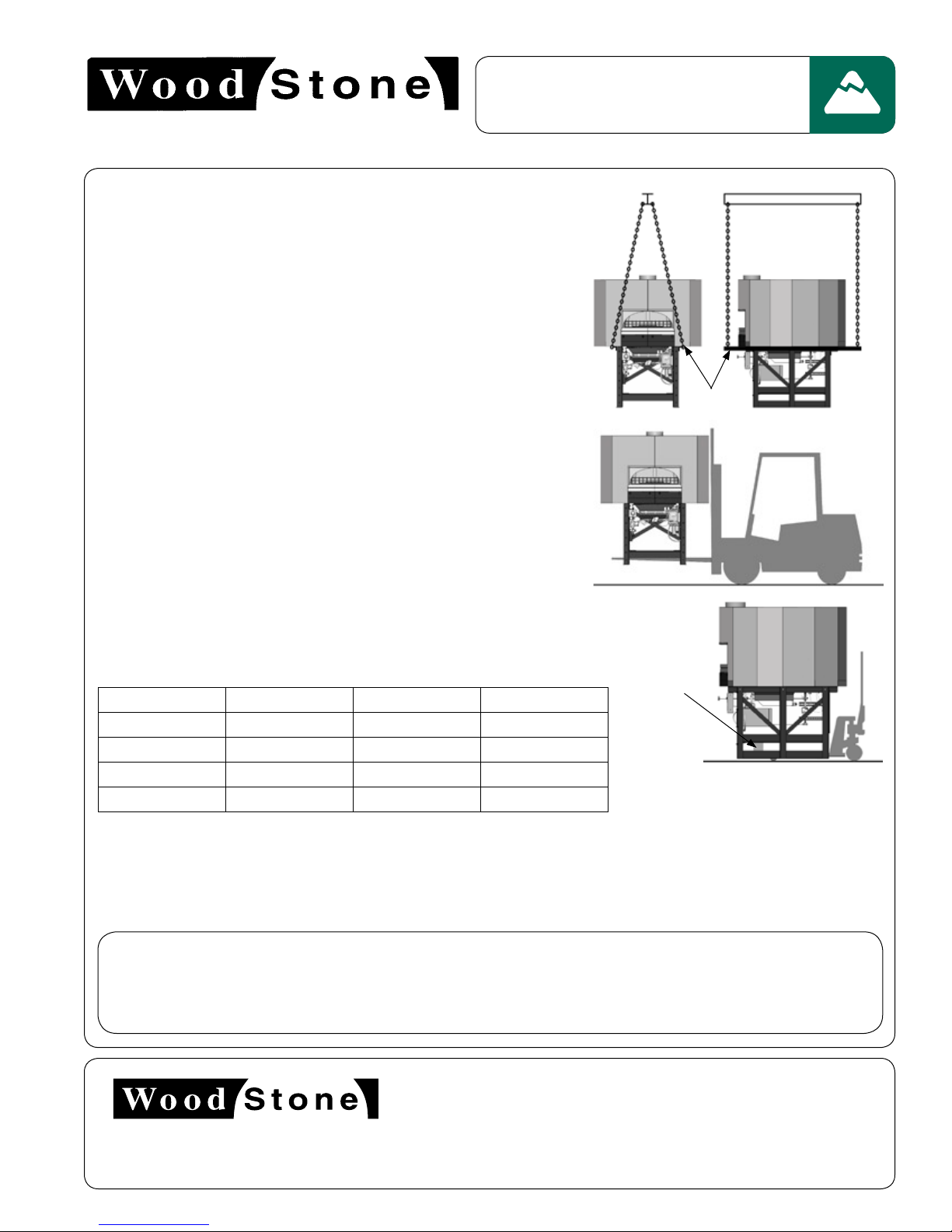
3. USING A PALLET JACK
Once the appliance has been removed from the delivery vehicle, it can
easily be moved on flat surfaces using a pallet jack. To lift with a pallet
jack, remove the front and rear angle iron stabilizers from the base of
the stand and place a stout 4x4 post through the fork pocket as shown.
THE APPLIANCE IS VERY TOP-HEAVY, MOVING THE APPLIANCE UP OR
DOWN A RAMP ON A PALLET JACK IS NOT SAFE!
Contact Wood Stone if the appliance must be turned on its side for specific instructions. Moving a Wood Stone
appliance can present interesting challenges to even the most experienced riggers. Take your time, use your head, secure
the proper equipment and make safety your first priority. Please don’t hesitate to call the factory for technical support.
DO NOT TURN THE APPLIANCE ON ITS SIDE!
DELIVERY NOTE:The customer will receive a Shipping Notification when the unit leaves the Wood Stone
factory. This will include a PRO# and a trucking company contact number. Wood Stone recommends that you
confirm the delivery date/time with the trucking company before committing to heavy equipment and/or labor.
Our goal is a smooth and safe delivery. Thank you.
2. USING A FORKLIFT
Be sure to use a forklift rated to lift more than the appliance weighs as
shown below. Fork length must be at least 6 feet, if not, fork extensions
should be used. The stand is equipped with fork pockets just above the
angle iron base. The appliance is very top heavy so spread the forks as far
apart as possible.
4x4 post
LIFTING THE APPLIANCE
1. USING A CRANE
The appliance arrives with four lifting eyes attached. When craning use a
spreader bar with a two-legged sling rigged on each end. The spreader
bar should be of a sufficient length to keep the sling from contacting the
appliance.
NOTE: Once lifting eyes are no longer needed, remove the lifting eyes one
at a time AND BE SURE TO REPLACE THE BOLTS THAT ATTACH THE
APPLIANCE TO THE STAND.
Lifting Eyes
UNLOADING AND MOVING

5
An ongoing program of product improvement may require us to change
specifications without notice. MH-W-IR
Revised November 2009
Wood Stone Corporation
1801 W. Bakerview Rd.
Bellingham, WA 98226 USA
Toll Free (800) 578-6836
Tel (360) 650-1111
Fax (360) 734-0223
Mountain Series Installation and Operation Manual
inStaLLation CLearanCeS
IF THIS APPLIANCE IS NOT PROPERLY INSTALLED A FIRE MAY RESULT. TO REDUCE THE RISK OF FIRE, FOLLOW
THESE INSTALLATION INSTRUCTIONS. A MAJOR CAUSE OF APPLIANCE RELATED FIRES IS FAILURE TO MAINTAIN
REQUIRED CLEARANCES (AIR SPACES) TO COMBUSTIBLE MATERIALS. IT IS OF UTMOST IMPORTANCE THAT THIS
APPLIANCE BE INSTALLED ONLY IN ACCORDANCE WITH THESE INSTRUCTIONS.
!
WARNING: Installation and servicing of this product could expose you to glasswool/ceramic
fibers as well as Calcium Silicate dust. ALWAYS WEAR RESPIRATORY AND EYE PROTECTION
WHEN INSTALLING OR SERVICING THIS APPLIANCE. Please read this entire manual before you
install the appliance. Failure to follow instructions may result in property damage, bodily injury
or even death. Contact your local building or fire officials about restrictions and installation
inspection in your area.
c. Install this appliance only on a non-combustible floor surface. The non-combustible floor surface should extend 30"
out in front of the appliance, and extend 30" to either side of the appliance doorway.
CLEARANCES
a. The Wood Stone MH-W-IR should have a minimum 1'’clearance to combustibles from all sides, and 6" clearance
to combustibles from the top (See page 6) If building a facade that will contact the appliance, use completely non-
combustible materials*. Please note that standard dry-wall (or sheet rock) is considered a combustible.
b. Any facade above and/or 6" to either side of the appliance doorway, must be constructed of non-combustible building
materials.
NOTICE: FOR STUCCO COVERED APPLIANCES (MODEL NUMBERS ENDING IN 'S') 36” CLEARANCE TO COMBUSTIBLE
BUILDING MATERIALS IS REQUIRED
*When non-combustible building materials contact the body of the appliance, the clearances to combustibles are transferred
to those non-combustibles.
INSTALLATION CLEARANCES

6
An ongoing program of product improvement may require us to change
specifications without notice. MH-W-IR
Revised November 2009
Wood Stone Corporation
1801 W. Bakerview Rd.
Bellingham, WA 98226 USA
Toll Free (800) 578-6836
Tel (360) 650-1111
Fax (360) 734-0223
Mountain Series Installation and Operation Manual
inStaLLation CLearanCeS
THE FOLLOWING CLEARANCE INFORMATION APPLIES TO ALL
WOOD STONE MH SERIES (NON-STUCCO) APPLIANCES
WARNING: Do not pack required air
spaces with insulation or other material.
6"
1" Side clearance to combustible
building materials.
6" Top clearance to combustible
building materials.
Any facade materials above and 6" to
either side of the doorway of the appliance,
must be NON-COMBUSTIBLE.
Note: 0" side and top clearance
to non-combustible materials,
however the respective clearances
to combustibles are transferred to
those non-combustibles.
Combustible Building Material
Hatched area represents area above
and 6" to either side of the appliance
doorway.

7
An ongoing program of product improvement may require us to change
specifications without notice. MH-W-IR
Revised November 2009
Wood Stone Corporation
1801 W. Bakerview Rd.
Bellingham, WA 98226 USA
Toll Free (800) 578-6836
Tel (360) 650-1111
Fax (360) 734-0223
Mountain Series Installation and Operation Manual
FaCade detaiLS
Hatched areas shall not be exposed after installation of facade.
Any facade above and/or within 6" to either side of the doorway
must be constructed of non-combustible building materials. All
surfaces in this area should also be easily cleanable.
Removable Service Panel.Allows access for service
of gas and electrical components.If this panel is not
used,access and air intake of equivalent dimensions
MUST be provided in this same location.
If using an exhaust hood over the appliance, make
sure your facade allows for the proper access for
removal of the hood filters!
Go to www.woodstonehome.com for detailed instructions for
constructing a facade around a Wood Stone Appliance.
FACADE DETAILS FOR THE WOOD STONE MH SERIES APPLIANCES
FACADE DETAILS

8
An ongoing program of product improvement may require us to change
specifications without notice. MH-W-IR
Revised November 2009
Wood Stone Corporation
1801 W. Bakerview Rd.
Bellingham, WA 98226 USA
Toll Free (800) 578-6836
Tel (360) 650-1111
Fax (360) 734-0223
Mountain Series Installation and Operation Manual
outdoor inStaLLationS
The Residential Mountain Series model appliances are ETL approved for outdoor installation. When installed outdoors,
the open area beneath the appliance must be enclosed, with the exception of the perforated area on the front service
panel for air intake. The appliance may be installed in a weatherproof enclosure. If so be sure to maintain all clearances
and adhere to the installation requirements included in this manual.
Lower Lagging Kit
Stand Wrap Kit
Wood Stone also offers the following options to
enclose the area beneath the appliance:
KEEP THE AREA AROUND AND BENEATH THE APPLIANCE CLEAR OF GRASS LEAVES, AND OTHER
COMBUSTIBLE MATERIALS.
OUTDOOR INSTALLATIONS
outdoor installations

9
An ongoing program of product improvement may require us to change
specifications without notice. MH-W-IR
Revised November 2009
Wood Stone Corporation
1801 W. Bakerview Rd.
Bellingham, WA 98226 USA
Toll Free (800) 578-6836
Tel (360) 650-1111
Fax (360) 734-0223
Mountain Series Installation and Operation Manual
GaS inLet preSSureS
The Wood Stone Gas appliances are equipped with a 3/4" NPT gas connection. Have a licensed gas installer provide the
hook-up and test all fittings and pipe connections for leaks. Use approved gas leak detectors (soap solutions or equivalent)
over and around the fittings and pipe connections. DO NOT USE FLAME TO TEST FOR LEAKS!
SV-1 is the gas control valve that operates the underfloor infrared burner. SV-1 is located directly behind the service/
intake panel and in front of the under floor infrared burner.
The manifold pressure test port for the infrared under floor burner is a 1/8" NPT plugged tapping located near the left
end of the burner manifold.
The burner manifold pressures have been adjusted and tested at the factory. A variety of factors can influence these
pressures, so be sure to test the individual burner manifold pressures and adjust the valves as necessary to achieve the
required pressures. Note: The gas valves are shipped in the ON position.
GAS INLET PRESSURES
Inlet pressure must be within the above ranges when the oven is running, and when the oven is off. No external regulator
is required when inlet pressures are within the ranges above. If inlet pressure exceeds 14” W.C. (1/2 psi), an external
regulator, by others, is required to prevent damage to the oven. If inlet pressure is below the minimum pressures shown
above, adjustment or modifications to the supply system will need to be made by the pipe installer and or the gas
supplier.
Proper gas inlet pressures are as follows:
Natural Gas – 6.5” W.C. min to 14” W.C. max
Propane (LP) – 10.5” W.C. min to 14” W.C. max
It is the responsibility of the installer to verify proper gas inlet (supply) pressure to the oven. Problems caused by
improper gas inlet pressure are not covered by the oven warranty. Proper gas inlet pressure is critical to the operation and
performance of the oven.
GAS inlet preSSureS

10
An ongoing program of product improvement may require us to change
specifications without notice. MH-W-IR
Revised November 2009
Wood Stone Corporation
1801 W. Bakerview Rd.
Bellingham, WA 98226 USA
Toll Free (800) 578-6836
Tel (360) 650-1111
Fax (360) 734-0223
Mountain Series Installation and Operation Manual
GaS SpeCiFiCationS
Natural Gas BTU input rates for Wood Stone wood/gas appliances.
Propane BTU input rates for Wood Stone wood/gas appliances.
Model Hourly BTU Input Rate
WS-MS-4-W-IR-NG 47,000
WS-MS-5-W-IR-NG 83,000
WS-MS-6-W-IR-NG 83,000
WS-MS-7-W-IR-NG 97,000
Model Hourly BTU Input Rate
WS-MS-4-W-IR-LP 42,000
WS-MS-5-W-IR-LP 65,000
WS-MS-6-W-IR-LP 65,000
WS-MS-7-W-IR-LP 85,000
Model SV-1
WS-MH-4-W-IR-LP 9”
WS-MH-5-W-IR-LP 9”
WS-MH-6-W-IR-LP 9”
WS-MH-7-W-IR-LP 9.2”
Model SV-1
WS-MH-4-W-IR-NG 3.5”
WS-MH-5-W-IR-NG 3.5”
WS-MH-6-W-IR-NG 3.5”
WS-MH-7-W-IR-NG 3.5”
Factory specified individual burner manifold pressures for models equipped to burn Natural Gas (NG).
Factory specified individual burner manifold pressures for models equipped to burn Propane (LP).
GAS SpecificAtionS

11
An ongoing program of product improvement may require us to change
specifications without notice. MH-W-IR
Revised November 2009
Wood Stone Corporation
1801 W. Bakerview Rd.
Bellingham, WA 98226 USA
Toll Free (800) 578-6836
Tel (360) 650-1111
Fax (360) 734-0223
Mountain Series Installation and Operation Manual
GaS Code LimitationS
GAS CODE LIMITATIONS
The installation of this appliance must conform with local codes, or in the absence of local codes,with the National
Fuel Gas Code,ANSI Z223.1,The Natural Gas installation Code CAN/CGA-B149.1 or the Propane Installation Code,
CAN/CGA-B149.2, as applicable including:
The appliance and its individual shutoff valve (supplied by others) must be disconnected from the gas supply
piping system during any pressure testing of that system at test pressures in excess of 1/2 psi (3.45 kPa).
The appliance must be isolated from the gas supply piping system by closing its individual manual shutoff
valve (supplied by others) during any pressure testing of the gas supply piping system at test pressure, equal
to or less than 1/2 psi (3.45 kPa).
Wood Stone recommends that the appliance’s individual shutoff valve (supplied by others) be left readily
accessible. Wood Stone also recommends that inspection and maintenance of the burners and gas piping
connections of this appliance be performed at regularly scheduled intervals and only by professional gas
appliance service agencies.
GAS code limitAtionS

12
An ongoing program of product improvement may require us to change
specifications without notice. MH-W-IR
Revised November 2009
Wood Stone Corporation
1801 W. Bakerview Rd.
Bellingham, WA 98226 USA
Toll Free (800) 578-6836
Tel (360) 650-1111
Fax (360) 734-0223
Mountain Series Installation and Operation Manual
eLeCtriCaL SpeCiFiCationS
This appliance must be electrically grounded in accordance with local codes, or in the absence of local codes,
with the National Electrical code, ANSI/NFPA 70 or the Canadian Electrical Code, CSA C22.1 as applicable.
If this appliance was provided with a cord, the cord is equipped with a 3 prong grounding plug for your protection
against shock hazard and should be plugged directly into a properly grounded receptacle. Do not cut or remove
the grounding prong from the plug.
ELECTRICAL
Incoming power should be connected to the terminal strip located in the transformer junction box beneath the
appliance. (See page 16 for diagram).
The standard appliance model comes configured for connection to a 120 V circuit. Always refer to the equipment
data plate beneath the appliance to verify the proper voltage. The voltage is also specified on the transformer
box cover. Never connect an appliance rated 120 V to a 240 V circuit or vice versa.
It is recommended that the appliance be connected to its own individual branch circuit. Have a licensed electrician
connect the appliance to the appropriate 120 V circuit.
Electrical diagrams are located directly to the right, behind the removable service/intake panel of the appliance
as well as inside the control box. Electrical diagrams are also located in this manual on page 28. See page 17
of this manual for location of the transformer housing.
Electrical Ratings:
120 V, 2 amp
ELECTRICAL GROUNDING
WARNING FOR APPLIANCES EQUIPPED WITH A POWER CORD
ELECTRICAL SPECIFICATIONS

13
An ongoing program of product improvement may require us to change
specifications without notice. MH-W-IR
Revised November 2009
Wood Stone Corporation
1801 W. Bakerview Rd.
Bellingham, WA 98226 USA
Toll Free (800) 578-6836
Tel (360) 650-1111
Fax (360) 734-0223
Mountain Series Installation and Operation Manual
VentinG the appLianCe
VENTING
The following are the manufacturer’s recommendations for venting the Wood Stone MH (Mountain Home Series) W-IR. It
is never appropriate to use “B vent” in any part of an exhaust system connected to a Wood Stone appliance. All ducting
material must be Listed to UL 103 and manufactured to the specifications of a grease duct. Submit your venting plans to
your local authorities before proceeding with your installation, as there may be additional requirements in your area.
Model Series Flue Collar
Mt. Chuckanut WS-MH-4 8 Inch O.D.
Mt. Adams WS-MH-5 10 Inch O.D.
Mt. Baker WS-MH-6 10 Inch O.D.
Mt. Rainier WS-MH-7 10 Inch O.D.
When using a direct connection as described above, the duct must be attached to the appliance flue collar with
a full perimeter weld, or a Listed connector.
Install venting system in accordance with the duct manufacturer's instructions and in accordance with all local
codes. All field built components should be built to the applicable codes and standards and are subject to the
approval of the authority having jurisdiction.
2. A Listed Type 1 Exhaust Hood or one that is constructed and installed in accordance with all relevant Local
and National Codes. Wood Stone offers eyebrow-type hoods designed specifically for Wood Stone Appliances.
See specification sheet on ventilators for Wood Stone Appliances.
THERE ARE TWO OPTIONS:
1. A power ventilated building heating appliance chimney, listed to UL 103, also listed as a grease duct, connected
directly to the appliance flue collar. The power ventilator (fan) must be rated for a minimum of 450 degrees F.
Use a stack or curb mounted fan. Wood Stone does not recommend the use of an in-line fan. A field built grease
duct, constructed and installed to the specifications of a grease duct as detailed in NFPA 96 or the International
Mechanical Code, may also be used.
A static pressure of -0.14 inches water column is necessary at the appliance flue collar to ensure that flue gas
temperatures do not exceed 450 degrees Fahrenheit (F) at the fan inlet. The CFM required to attain this static
pressure will depend on the configuration of your particular installation but will probably be between 500 and
700 CFM. This pressure measurement may be taken by inserting the end of the probe through the oven doorway,
upward to the oven flue collar.
VENTING THE APPLIANCE

14
An ongoing program of product improvement may require us to change
specifications without notice. MH-W-IR
Revised November 2009
Wood Stone Corporation
1801 W. Bakerview Rd.
Bellingham, WA 98226 USA
Toll Free (800) 578-6836
Tel (360) 650-1111
Fax (360) 734-0223
Mountain Series Installation and Operation Manual
VentinG the appLianCe
Allow sufficient opening
between any facade and
the inside edge of the
front of the hood to allow
for filter removal and
hood cleaning.
8"
VERY IMPORTANT! WOOD STONE RECOMMENDS THAT YOU SUBMIT YOUR VENTING PLANS TO LOCAL CODE
AUTHORITIES BEFORE PROCEEDING WITH INSTALLATION.
Note that the notch of the hood is even with the front edge of the appliance. The hood should be installed
in accordance with the hood manufacturer's instructions, and with NFPA 96 and/or the applicable local and
national codes.
INSTALLATION VIEWS OF A WOOD STONE HOOD

15
An ongoing program of product improvement may require us to change
specifications without notice. MH-W-IR
Revised November 2009
Wood Stone Corporation
1801 W. Bakerview Rd.
Bellingham, WA 98226 USA
Toll Free (800) 578-6836
Tel (360) 650-1111
Fax (360) 734-0223
Mountain Series Installation and Operation Manual
aSSemBLY
ASSEMBLY
1. Mount the appliance mantle (if provided) using the hardware provided. (See figure on page 16).
2. Mount the stainless steel toe kick to the front of the stand, near the floor using the hardware provided (See figure on
page 17). If your appliance was shipped with a lower facade extension there is no toe kick required.
3. Mount the service/intake panel to the brackets on the front of the stand, directly below the doorway, using the hardware
provided (See figure on page 17, if your appliance was shipped with the optional facade extensions, page 18).
a. Do not obstruct the flow of combustion and ventilation air between the toe kick and the bottom of the service/intake
panel.
b. This panel is the only access for servicing the gas and electrical components of the appliance so it must be left
accessible and removable.
4. The following applies to stucco finish appliances only (Models ending with S):
a. Once the appliance has been set in place, cover wire mesh and metal lathing with no less than 1 inch of stucco
(see page 19 for diagram).
ASSEMBLY

16
An ongoing program of product improvement may require us to change
specifications without notice. MH-W-IR
Revised November 2009
Wood Stone Corporation
1801 W. Bakerview Rd.
Bellingham, WA 98226 USA
Toll Free (800) 578-6836
Tel (360) 650-1111
Fax (360) 734-0223
Mountain Series Installation and Operation Manual
mantLe mountinG
The initial steps are the same for mounting either a stainless mantle or a bracket for a granite mantle.
2. Next, place (2) spacer washers
on each stud.
4. Finally, place one final washer
(stainless steel) and a cap nut on
each stud. Tighten the cap nuts
so the mantle is securely held in
place.
5. Using the high temperature silicone (provided), fill any gaps between the hearth and the mantle flange. Gaps between
the mantle flange and the stainless steel doorway frame may also need to be filled with a small amount of the silicone
compound.
INSTALLATION OF GRANITE - After completing the steps outlined above, apply a generous amount of silicone adhesive
(provided) to the top of the steel mantle bracket.
Put the stone in place and apply light
pressure to seat it properly. Make sure that
the angle in the granite lines up with the
angle in the bracket. Allow the adhesive
to set for several hours before filling
any gap between the stone slab and the
metal bracket with the silicone compound
(provided). Clean up any adhesive and/or
silicone before it dries!
1. Begin by installing the threaded
studs into the clip nuts below the
appliance doorway (3 or 4 turns is
sufficient).
3. Position the mantle (or bracket)
on the appliance, make sure the
rear flange rests on the floor of the
appliance (you may need an extra
pair of hands).
MANTLE MOUNTING

17
An ongoing program of product improvement may require us to change
specifications without notice. MH-W-IR
Revised November 2009
Wood Stone Corporation
1801 W. Bakerview Rd.
Bellingham, WA 98226 USA
Toll Free (800) 578-6836
Tel (360) 650-1111
Fax (360) 734-0223
Mountain Series Installation and Operation Manual
Front paneL aSSemBLY
STANDARD FRONT PANEL AND TOE KICK
View of Throttle Assembly
The throttle knob position can be adjusted
inward or outward by loosening the clamp and
sliding the throttle knob assembly to the desired
position. Be sure to retighten the clamp once the
throttle knob is in the desired position.
Throttle Knob
Throttle Bracket
Clamp
Throttle Rod Extension
Throttle Valve
Cotter Key
FRONT PANEL ASSEMBLY

18
An ongoing program of product improvement may require us to change
specifications without notice. MH-W-IR
Revised November 2009
Wood Stone Corporation
1801 W. Bakerview Rd.
Bellingham, WA 98226 USA
Toll Free (800) 578-6836
Tel (360) 650-1111
Fax (360) 734-0223
Mountain Series Installation and Operation Manual
optionaL LoWer eXtenSion
APPLIANCES EQUIPPED WITH OPTIONAL LOWER EXTENSION
OPTIONAL LOWER EXTENSION

19
An ongoing program of product improvement may require us to change
specifications without notice. MH-W-IR
Revised November 2009
Wood Stone Corporation
1801 W. Bakerview Rd.
Bellingham, WA 98226 USA
Toll Free (800) 578-6836
Tel (360) 650-1111
Fax (360) 734-0223
Mountain Series Installation and Operation Manual
StuCCo appLiCation
MINIMUM STUCCO APPLICATION IS 1"
TRADITIONAL
STUCCO MIX
1 part masonry cement
1part regular cement
5parts sand
STUCCO PREMIX IS
PROBABLY AVAILABLE
AT YOUR LOCAL
LUMBER YARD
OR BUILDING SUPPLY
STORE
1part premix
2parts sand
This figure depicts the application of stucco on a Wood Stone appliance. Use no less than 1 inch of stucco coating to cover
all exposed metal lathing on the appliance. Maintain a minimum of 36 inch clearance from top and sides of appliance to
all combustible surfaces.
STUCCO APPLICATION
This manual suits for next models
3
Table of contents
Other Wood Stone Cooker manuals
Popular Cooker manuals by other brands

Livecook
Livecook LC-SV-08 user manual

Siemens
Siemens HE63AB 21 Series instruction manual

Parkinson Cowan
Parkinson Cowan Lyric 55GS1 Operating and installation instructions

Parkinson Cowan
Parkinson Cowan CHIQUE user manual

Hotpoint
Hotpoint 6 DOG instructions

Electrolux
Electrolux EKM 6701 X Instruction booklet