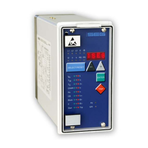
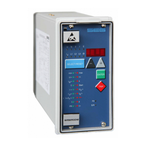
Manual MRI3-ITER GB Woodward
DOK-TD-MRI3 ITERE Rev.A 3
Contents
1.Introduction and Application ......................................................................5
2.Features and characteristics ......................................................................6
3.Design...........................................................................................................7
3.1Connections ........................................................................................................................7
3.1.1Analogue input circuits ....................................................................................................8
3.1.2Output relays ...................................................................................................................9
3.2Relay output contacts..........................................................................................................9
3.2.1Blocking input ................................................................................................................10
3.2.2External reset input .......................................................................................................10
3.2.3Fault recorder ................................................................................................................10
3.3Front plate .........................................................................................................................12
4.Working principle.......................................................................................14
4.1Analog circuits ...................................................................................................................14
4.2Digital circuits ....................................................................................................................14
4.3Thermal replica..................................................................................................................15
4.3.1Definitions......................................................................................................................15
4.4Algorithm ...........................................................................................................................16
4.5Earth fault protection .........................................................................................................19
4.5.1Generator stator earth fault protection ..........................................................................19
4.5.2System earth fault protection ........................................................................................19
4.6Earth-fault directional feature (ER-relay type)...................................................................20
4.7Demand imposed on the main current transformers.........................................................22
5.Operation and settings..............................................................................23
5.1Display...............................................................................................................................23
5.1.1LEDs..............................................................................................................................25
5.2Setting procedure..............................................................................................................27
5.3System parameter.............................................................................................................27
5.3.1Display of measuring values as primary quantities (Iprim phase)...................................27
5.3.2Display of earth current as primary quantity (Iprim earth) ...............................................27
5.3.3Display of residual voltage UE as primary quantity (Uprim/Usec).....................................27
5.3.4Voltage transformer connection for residual voltage measuring (3pha/e-n/1:1)...........27
5.3.5Nominal frequency ........................................................................................................28
5.3.6Display of the activation storage (FLSH/NOFL)............................................................28
5.3.7Parameter switch/external triggering of the fault recorder ............................................28
5.4Protection parameters.......................................................................................................29
5.4.1Pickup value of the thermal overload protection IB,A and IB,T ........................................29
5.4.2Constant k .....................................................................................................................29
5.4.3Energizing delay (time) for the thermal overload ..........................................................29
5.4.4Time constant .............................................................................................................29
5.4.5Pickup current for phase over current element (I>) ......................................................29
5.4.6Time current characteristics for phase overcurrent element (CHAR I>).......................30
5.4.7Trip delay or time multiplier for phase over current element (tI>) .................................30
5.4.8Reset setting for inverse time tripping characteristics in the phase current path .........30
5.4.9Current setting for high set element (I>>) .....................................................................30
5.4.10Trip delay for high set element (tI>>) ........................................................................30
5.4.11Pickup value for residual voltage UE(ITER-relay type).............................................31
5.4.12Pickup current for earth fault element (IE>)................................................................31
5.4.13WARN/TRIP changeover ..........................................................................................31
5.4.14Time current characteristics for earth fault element (CHAR IE) (not ER device type) ... 31
5.4.15Trip delay or time multiplier for earth fault element (tIE>)...........................................31
5.4.16Resetting time for inverse time earth fault element (not ER-relay type) ...................31
5.4.17Current setting for high set element of earth fault supervision (IE>>)........................31
5.4.18Trip delay for high set element of earth fault supervision (tIE>>)................................32
5.4.19COS/SIN Measurement (ER - relay type) .................................................................32
5.4.20Block/Trip – time (only ITE-device type) ...................................................................32
5.4.21Circuit breaker failure protection tCBFP .......................................................................32
5.4.22Adjustment of the slave address ...............................................................................32
