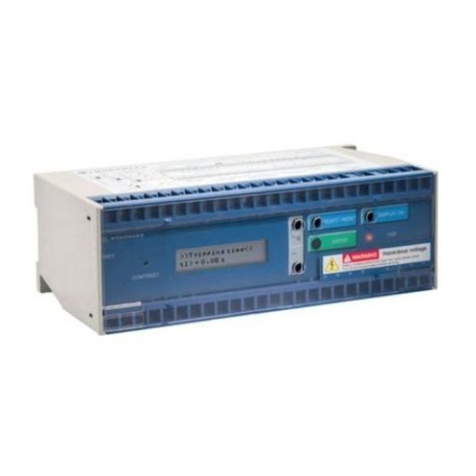
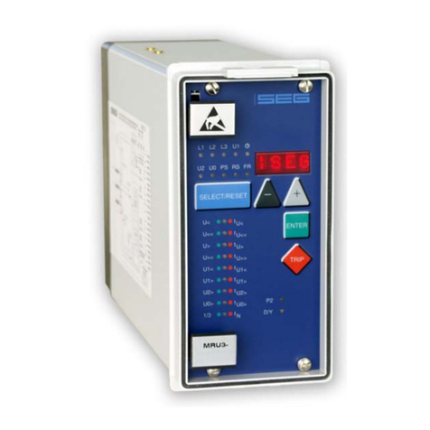
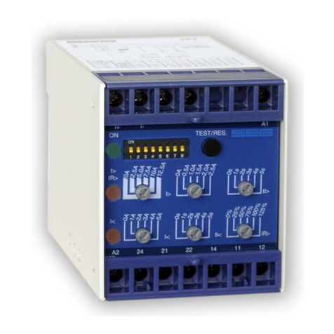
Woodward Manual MRI3 GB
4 DOK-TD-MRI3 Rev.A
5.4.19Circuit breaker failure protection tCBFP ................................................................... 36
5.4.20Adjustment of the slave address .............................................................................. 36
5.4.21Setting of Baud-rate (applies for Modbus Protocol only).......................................... 36
5.4.22Setting of parity (applies for Modbus Protocol only)................................................. 36
5.5Fault recorder ................................................................................................................... 37
5.5.1Adjustment of the fault recorder ................................................................................... 37
5.5.2Number of the fault recordings ..................................................................................... 37
5.5.35.5.3 Adjustment of trigger occurrences....................................................................... 37
5.5.4Pre-trigger time (Tpre) .................................................................................................. 37
5.6Adjustment of the clock..................................................................................................... 38
5.7Additional functions........................................................................................................... 38
5.7.1Blocking the protection functions and assignment of the output relays ....................... 38
5.8Setting value calculation ................................................................................................... 40
5.8.1Definite time overcurrent element................................................................................. 40
5.8.2Inverse time overcurrent element ................................................................................. 41
5.9Indication of measuring and fault values .......................................................................... 41
5.9.1Indication of measuring values ..................................................................................... 41
5.9.2Units of the measuring values displayed ..................................................................... 42
5.9.3Indication of fault data................................................................................................... 44
5.9.4Fault memory................................................................................................................ 44
5.10Reset................................................................................................................................. 45
5.10.1Erasure of fault storage ............................................................................................ 45
6.Relay testing and commissioning............................................................46
6.1Power-On.......................................................................................................................... 46
6.2Testing the output relays and LEDs ................................................................................. 46
6.3Checking the set values.................................................................................................... 46
6.4Secondary injection test.................................................................................................... 47
6.4.1Test equipment ............................................................................................................. 47
6.4.2Example of test circuit for MRI3 relays without directional feature............................... 47
6.4.3Checking the input circuits and measured values ........................................................ 48
6.4.4Checking the operating and resetting values of the relay ............................................ 48
6.4.5Checking the relay operating time ................................................................................ 48
6.4.6Checking the high set element of the relay .................................................................. 48
6.4.7Example of a test circuit for MRI3 relay with directional feature................................... 49
6.4.8Test circuit earth fault directional feature...................................................................... 51
6.4.9Checking the external blocking and reset functions ..................................................... 52
6.4.10Testing the external blocking with Block/Trip function.............................................. 52
6.4.11Test of the CB failure protection ............................................................................... 52
6.5Primary injection test ........................................................................................................ 53
6.6Maintenance ..................................................................................................................... 53
7.Technical data............................................................................................54
7.1Measuring input circuits .................................................................................................... 54
7.2Common data ................................................................................................................... 54
7.3Setting ranges and steps .................................................................................................. 55
7.3.1Time overcurrent protection (I-Type) ............................................................................ 55
7.3.2Earth fault protection (SR/YR-Type)............................................................................. 55
7.3.3Earth fault protection (E/X-Type) .................................................................................. 55
7.3.4Earth fault protection (ER/XR-Type)............................................................................. 56
7.3.5Block/Trip – time ........................................................................................................... 56
7.3.6Switch failure protection................................................................................................ 56
7.3.7Interface parameter ...................................................................................................... 56
7.3.8Parameter for the fault recorder ................................................................................... 56
7.3.9Inverse time overcurrent protection relay ..................................................................... 57
7.3.10Direction unit for phase overcurrent relay................................................................. 58
7.3.11Determination of earth fault direction (MRl3-ER/XR)................................................ 58
7.3.12Determination of earth fault direction (MRl3-SR/YR)................................................ 58
7.4Inverse time characteristics .............................................................................................. 59
7.5Output contacts................................................................................................................. 62
8.Order form..................................................................................................63


