manuals.online logo
Brands
  1. Home
  2. •
  3. Brands
  4. •
  5. Mastervolt
  6. •
  7. Relay
  8. •
  9. Mastervolt Digital AC 1x6A Operating manual

Mastervolt Digital AC 1x6A Operating manual

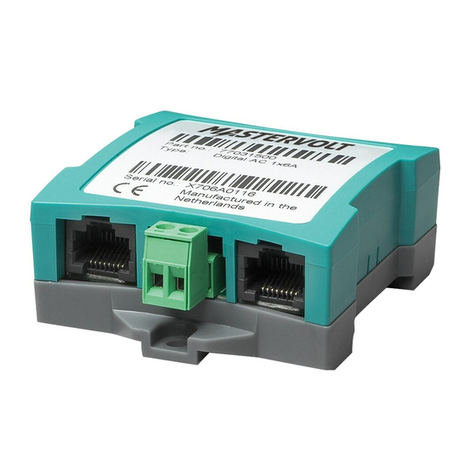
DIGITAL AC 1x6A
AC RELAY FOR DIGITAL SWITCHING
USER AND INSTALLATION MANUAL
10000017912/01
2
Digital AC 1x6A –User and installation manual
1. GENERAL INFORMATION
1.1 Use of this manual
This manual serves as a guideline for the safe and
effective operation of the Digital AC 1x6A. Read the
entire manual before using the Digital AC 1x6A. Keep
this manual in a secure place!
1.2 Liability
Mastervolt can accept no liability for:
•Consequential damage resulting from the use of
the Digital AC 1x6A.
•Possible errors in the included manual and the
consequences of these.
•Use that is inconsistent with the purpose of the
product.
1.3 Warranty
The Mastervolt product warranty covers the Digital
AC 1x6A for the first two years after the purchase
date, on the condition that the product is installed and
used according to the instructions in this manual.
Installation or use that do not comply with these in-
structions may result in under performance, damage
or failure of the product and may void this warranty.
The warranty is limited to the cost of repair and/or
replacement of the product. Costs of labor or shipping
are not covered by this warranty.
CAUTION!
Never remove the identification label.
This will void the warranty.
1.4 Disclaimer
Our products are subject to continual development
and improvement. Therefore, additions or modifica-
tions to the products may cause changes to the
technical data and functional specifications. No rights
can be derived from this document. Please consult
our most current Terms & Conditions of Sale.
1.5 Correct disposal of this product
This product is designed and manu-
factured with high quality materials and
components, which can be recycled
and reused. Please be informed about
the local separate collection system for
electrical and electronic products. Please act
according to your local rules and do not dispose of
your old products with your normal household waste.
The correct disposal of your old product will help
prevent potential negative consequences to the
environment and human health.
2. OPERATION
The Digital AC 1x6A operation is entirely MasterBus based. For information about MasterBus and the MasterBus
event structure, see www.mastervolt.com. The following table shows the relay functions.
Monitoring
Description
Factory
settings
Range
State
Relay can be switched On (activate) or
Standby
Standby
Standby/ Activate
Control
Change the state of the relay
Standby
Activate/ Standby
Configuration General
Language
Set the MasterBus Digital AC menu language
English
See specifications
Device name
Any name you wish with 12 characters max
AC Relay
1-12 characters
Events locked
Check box for installers to lock event
configuration. Only operable by installers.
Unchecked
Unchecked/
Checked
Shock resistance
(Installer menu)
For applications that experience large shocks
and/or vibration on a regular basis (heavy
duty/racing/etc).
Turn on* will make the relay more 'sticky' and
thus more resilient against shocks/vibrations.
Off
On/Off
Configuration Timing
Min. runtime
Check box to enable the function Minimum
runtime for switching the relay.
Unchecked
Unchecked/
Checked
Min. runtime
Minimum runtime setting
15 minutes
1-65535 minutes
Max. runtime
Check box to enable the function Maximum
runtime for relay switching the relay.
Unchecked
Unchecked/
Checked
Max. runtime
Maximum runtime setting
480 minutes
1-65535 minutes
* This mode will increase the energy usage of the interface (by about 8mA continuously) as it will keep some power applied to
the relay. This will keep the coil of the relay a little bit magnetized, which in turn will make it more 'sticky' to its current state.
Digital AC 1x6A –User and installation manual
3
Events
A MasterBus based device can initiate an action at another connected device. This is done by configuring Events.
A device can act as event source and as event target.
Other devices can control the relay of the Digital AC 1x6A by setting up an event at the source device with the
Digital AC 1x6A as target. The following example shows how a Digital Switch Input uses Switch 1 to control the
relay with a toggle action.
Event source
Event target
Event command
Event action
Switch 1
Digital AC
Activate
Toggle
Likewise, the Digital AC 1x6A can control other devices. The following example shows how event source "State" of
the Digital AC 1x6A, is used to control the feedback LED of a Digital Switch Input.
Event source
Event target
Event command
Event action
State
Switch input
Feed back 1
Copy
3. INSTALLATION
3.1 Overview
Insert the MasterBus cables, then connect the relay cables to the screw terminal input and outputs as
shown below.
Overview and functional scheme of the Digital AC 1x6A
3.2 Installation schemes
The Digital AC 1x6A is suitable for switching currents up to 6A. For currents above 6A you need an external relay
which is controlled by the Digital AC 1x6A. You also need to add a fuse like shown for load protection.
Installation schemes for currents up to 6A and above
4. EC DECLARATION OF CONFORMITY
This product is in conformity with the provision of the EC EMC directive 89/336/EEC
and amendments 92/31/EEC, 93/68/EEC. Standards applied:
Generic emission standard: EN 50081-1:1992,
Generic Immunity standard: EN 50082-1:1997,
Safety directive 2006/95/EC, with the following standard,
Low voltage standard: EN 60950: 2000.
1. Input
2. Output normally open
3. Communication LED, illuminating when the state is “activate”
MasterBus connector
Function:
Stand by: Relay is open,
Activate: 1 is connected to 2,
Maximum relay current: 6A.
External relay
4
Digital AC 1x6A –User and installation manual
5. SPECIFICATIONS
Dimensions in mm (inch) and connections
Model:
Digital AC 1x6A
Product code :
77031500
Delivery also includes:
Screw terminal, MasterBus cable, MasterBus Terminator, User manual
Function of instrument:
MasterBus controlled AC relay
Potential free contact:
1:C, 2:NO –6A / 230 V AC
Languages available:
English, Nederlands, Deutsch, Français, Castellano, Italiano, Norsk,
Svenska, Suomi, Dansk
Power consumption:
144 mW
MasterBus Powering:
No
Din rail mounting:
Yes, Din rail 30 mm [1.2 inch]
Protection degree:
IP 21
Dimensions:
66 x 78 x 32 mm [2.6 x 3.1 x 1.3 inch]; see drawing below
Weight:
Approx. 80 gr [0.18 lb]
Europe, Middle East & Africa
Customer Service
T: +31 (0) 20 34 22 100
E: [email protected]
Technical Support
T: +31 (0) 20 34 22 100
E: [email protected]
Location & Shipping
Mastervolt
Snijdersbergweg 93
1105 AN Amsterdam
The Netherlands
Americas & Caribbean
Customer Service
T: +1 800 307 6702, Option 1
E: [email protected]
Technical Support
T: +1 800 307 6702, Option 2
E: [email protected]
Location & Shipping
Power Products, LLC
N85 W12545 Westbrook Crossing
Menomonee Falls, Wisconsin 53051
United States
Asia Pacific
Customer Service
T: +64 9 415 7261 Option 1
E: [email protected]
Technical Support
T: +64 9 415 7261 Option 3
E: [email protected]
Location & Shipping
BEP Marine
42 Apollo Drive
Rosedale, Auckland 0632
New Zealand
Screw terminal
= MasterBus
connector
Copyright © 2020 Mastervolt. All rights reserved.
Reproduction, transfer, distribution or storage of part or all of the contents in this
document in any form without the prior written permission of Mastervolt is prohibited.

Other manuals for Digital AC 1x6A

2

This manual suits for next models

1

Other Mastervolt Relay manuals

Mastervolt Multipurpose Contact Output Operating manual

Mastervolt

Mastervolt Multipurpose Contact Output Operating manual

Mastervolt Charge Mate Pro 40 User manual

Mastervolt

Mastervolt Charge Mate Pro 40 User manual

Mastervolt 77030500 User manual

Mastervolt

Mastervolt 77030500 User manual

Mastervolt Digital AC 1x6A User manual

Mastervolt

Mastervolt Digital AC 1x6A User manual

Mastervolt Digital AC 1x6A User manual

Mastervolt

Mastervolt Digital AC 1x6A User manual

Mastervolt MLI Ultra Series Instruction Manual

Mastervolt

Mastervolt MLI Ultra Series Instruction Manual

Popular Relay manuals by other brands

Littelfuse PGR-8800 manual

Littelfuse

Littelfuse PGR-8800 manual

TOHO TRT-2416 Operation manual

TOHO

TOHO TRT-2416 Operation manual

ABB PMA Instruction leaflet

ABB

ABB PMA Instruction leaflet

ZIEHL STW81V operating manual

ZIEHL

ZIEHL STW81V operating manual

ABB CR324GXNS user guide

ABB

ABB CR324GXNS user guide

GE 12CEYG51B(-)D instructions

GE

GE 12CEYG51B(-)D instructions

Honeywell RP470A installation instructions

Honeywell

Honeywell RP470A installation instructions

Azoteq IQ Switch - ProxSense Series user guide

Azoteq

Azoteq IQ Switch - ProxSense Series user guide

Wieland SNV 4274SL Translation of the original instructions

Wieland

Wieland SNV 4274SL Translation of the original instructions

ABB Relion 620 Series Communication protocol manual

ABB

ABB Relion 620 Series Communication protocol manual

Climax CL-DR-RL16X8A installation guide

Climax

Climax CL-DR-RL16X8A installation guide

Zamel PNM-32 instruction manual

Zamel

Zamel PNM-32 instruction manual

ERL T-PRO 4000 quick start guide

ERL

ERL T-PRO 4000 quick start guide

Eaton Funke+Huster Fernsig TAR22 manual

Eaton

Eaton Funke+Huster Fernsig TAR22 manual

Novatek Volt Control RN-122 operating manual

Novatek

Novatek Volt Control RN-122 operating manual

Pickering PXI 4 145A Series manual

Pickering

Pickering PXI 4 145A Series manual

Omron G3RV-SL700-A Series manual

Omron

Omron G3RV-SL700-A Series manual

Pilz PNOZ s3 Series operating manual

Pilz

Pilz PNOZ s3 Series operating manual

manuals.online logo
manuals.online logoBrands
  • About & Mission
  • Contact us
  • Privacy Policy
  • Terms and Conditions

Copyright 2025 Manuals.Online. All Rights Reserved.