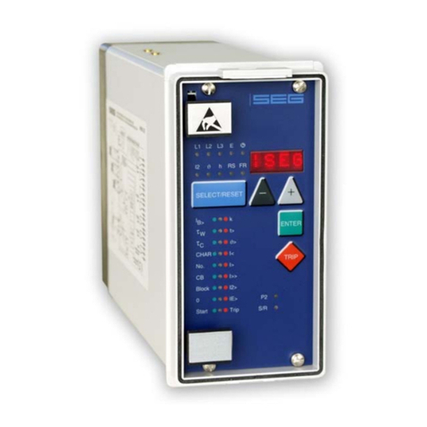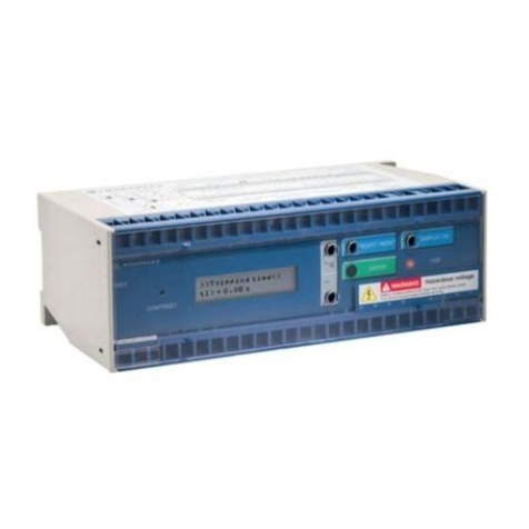
Manual MRU3-1 GB Woodward
TD_MRU3-1_09.08_GB_Rev.New 3
Contents
1.Introduction and application ....................................................................... 5
2.Features and characteristics....................................................................... 6
3.Design ........................................................................................................... 7
3.1Connections ...................................................................................................................... 7
3.1.1Analog input circuits ...................................................................................................... 8
3.1.2Blocking input................................................................................................................ 8
3.1.3Reset input .................................................................................................................... 8
3.1.4Output relays................................................................................................................. 8
3.1.5Fault recorder................................................................................................................ 8
3.1.6Parameter settings ...................................................................................................... 10
3.2LEDs ............................................................................................................................... 11
3.3Front plate ....................................................................................................................... 11
4.Working principle ....................................................................................... 12
4.1Analog circuits................................................................................................................. 12
4.2Digital circuits .................................................................................................................. 12
4.3Voltage supervision......................................................................................................... 12
4.3.1Selection of star or delta ............................................................................................. 13
4.4Blocking function ............................................................................................................. 14
5.Operations and settings ............................................................................ 15
5.1Display ............................................................................................................................ 15
5.2Setting procedure............................................................................................................ 17
5.3Systemparameter............................................................................................................ 17
5.3.1Display of residual voltage UEas primary quantity (Uprim/Usec) .................................... 17
5.3.2D/Y – Switch over........................................................................................................ 17
5.3.3Setting of nominal frequency....................................................................................... 18
5.3.4Display of the activation storage ................................................................................. 19
5.3.5Parameter switch/external triggering for the fault recorder.......................................... 19
5.4Protection parameters..................................................................................................... 20
5.4.11-phase or 3-phase U</U>-tripping............................................................................. 20
5.4.2Parameter setting of over- and undervoltage supervision........................................... 20
5.4.3Adjustment of the slave address ................................................................................. 20
5.4.4Setting of Baud-rate (applies for Modbus-Protocol only)............................................. 20
5.4.5Setting of parity (applies for Modbus-Protocol only).................................................... 20
5.5Parameter for the fault recorder ...................................................................................... 21
5.5.1Adjustment of the fault recorder .................................................................................. 21
5.5.2Number of the fault recordings .................................................................................... 21
5.5.3Adjustment of trigger occurrences............................................................................... 21
5.5.4Pre-trigger time (Tpre)................................................................................................... 21
5.6Date and time.................................................................................................................. 22
5.6.1Adjustment of the clock ............................................................................................... 22
5.7Indication of measuring values........................................................................................ 22
5.7.1Measuring indication ................................................................................................... 22
5.7.2Unit of the measuring values displayed....................................................................... 22
5.7.3Indication of fault memory data ................................................................................... 22
5.8Fault memory .................................................................................................................. 23
5.9Additional functions ......................................................................................................... 24
5.9.1Setting procedure for blocking the protection functions............................................... 24
5.9.2Reset........................................................................................................................... 25
5.9.3Erasure of fault storage............................................................................................... 25
6.Relay testing and commissioning ............................................................ 26
6.1Power-On ........................................................................................................................ 26
6.2Testing the output relays................................................................................................. 26
6.3Checking the set values .................................................................................................. 27
6.4Secondary injection test .................................................................................................. 28
6.4.1Test equipment ........................................................................................................... 28
6.4.2Example of the test circuit ........................................................................................... 28


