Workhorse Mercury compact dryer User manual

PN: 67-1465, REV: A, 3/13

2
Congratulaons on your purchase of
the Workhorse Products Mercury
Compact Dryer.
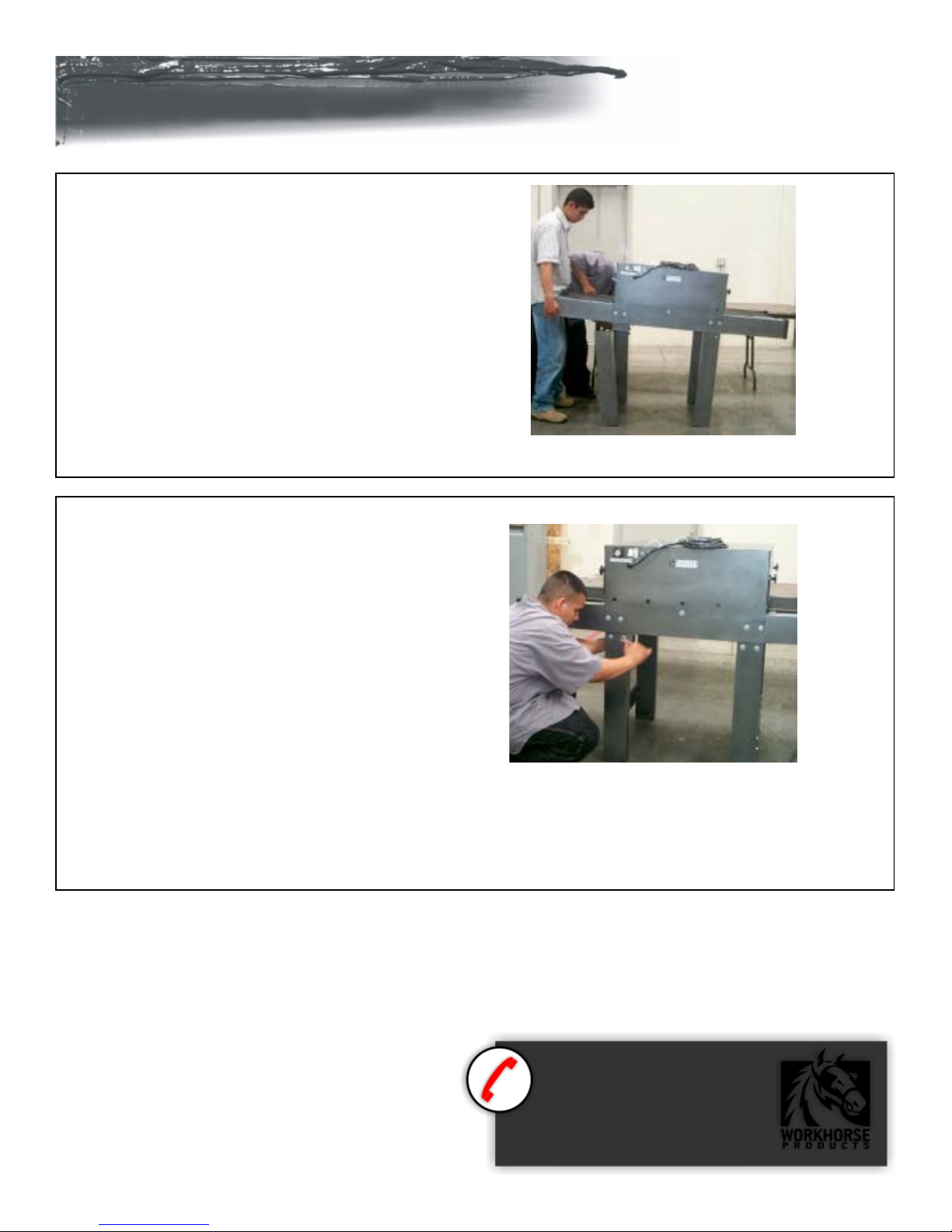
Check the crate for damage, DO NOT
accept the crate if damaged due to
improper handling during shipping.
Report any damage to the carrier at
once as well as Workhorse Products at
800-778-8779.
Inspect the crate contents
IMMEDIATELY while the carrier is sll
there. Our packaging has been
carefully designed to handle normal
shipping condions. However, we
cannot be responsible for damage by
the carrier. Upon rst sight of freight
damage nofy or point out to the
driver and le your claim with the
carrier, then nofy us.
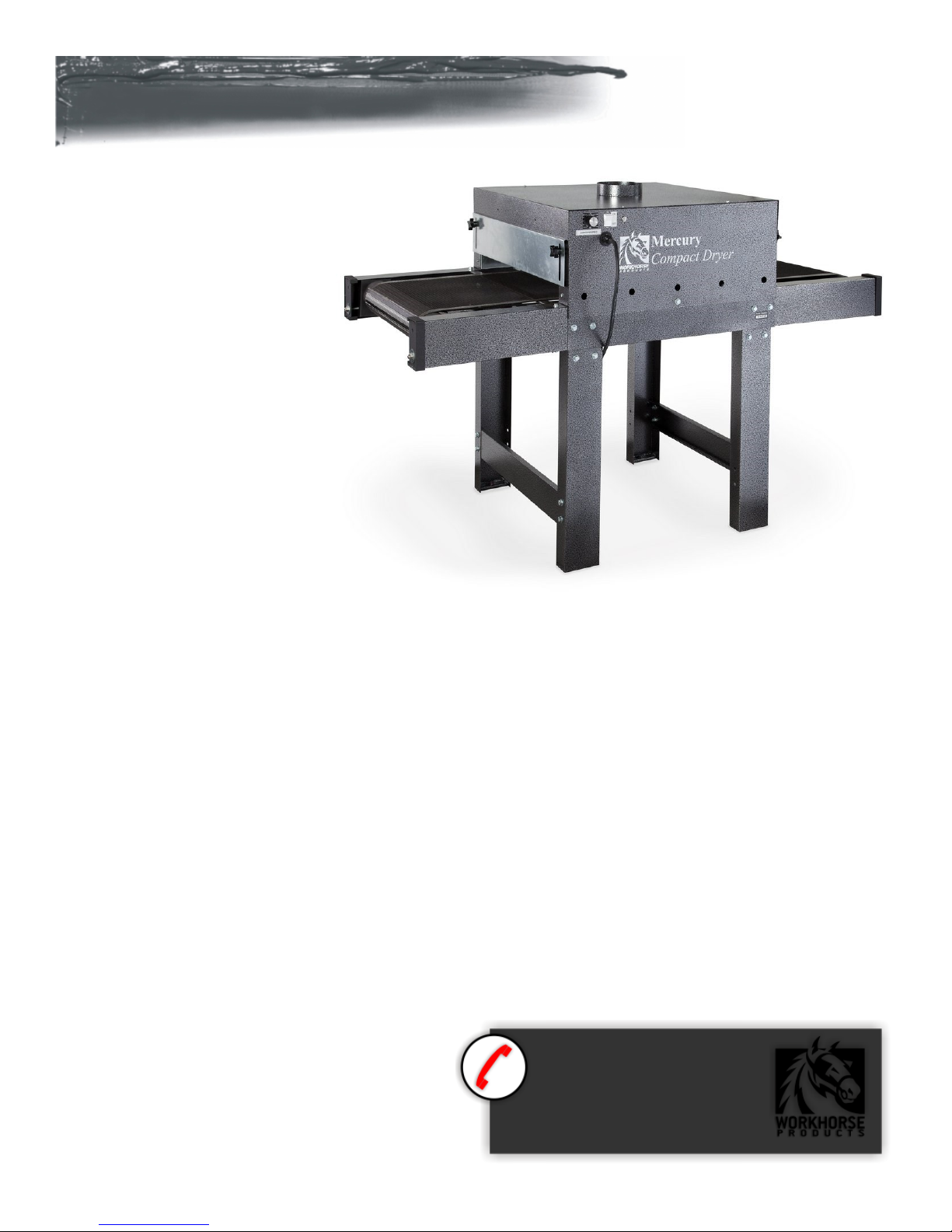
Features:
• 2300 WATTS OF POWER – The 30” heat chamber contains an 18”x20” infrared heat panel producing 2300 WATTS of power.
• Compact Size – The MECURY INFRARED COMPACT CONVEYOR DRYERS are compact enough to t almost anywhere having a foot
print of 32” (12.6cm) x 66” (26cm). It is ideal to use as a portable Dryer for those “on site” prinng jobs.
• Air Cooled Hood – The MECURY INFRARED COMPACT CONVEYOR DRYER features improved air ow to keep the hood cool.
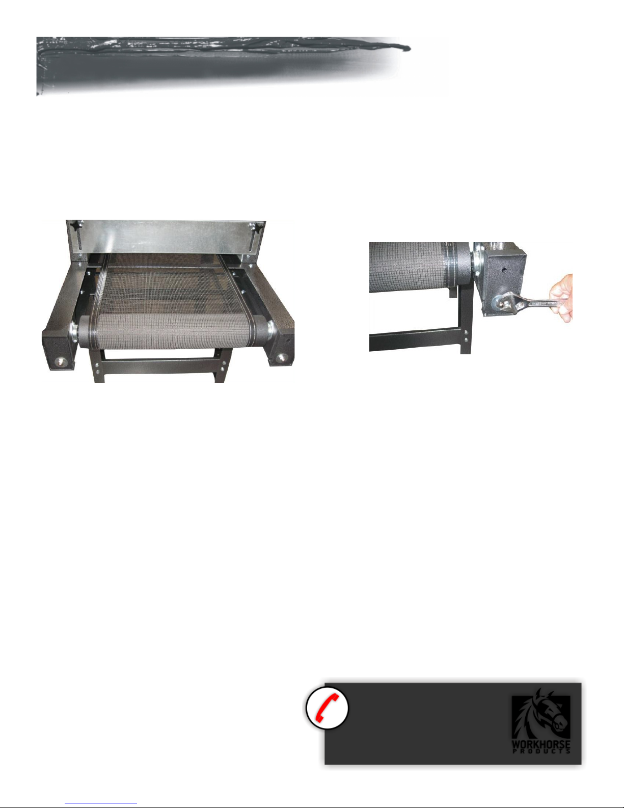
• Adjustable Chamber Openings – Sliding doors at the entrance and exit of the heat chamber improve heat stability for consistent
curing temperatures.
• Exhaust Ring – an external ring on top of the dryer allows hook up to a standard duct size to vent the dryer externally.
Questions? Give us a call!
800.778.8779
workhorseproducts.com
Visit our website at
The Workhorse MECURY INFRARED COMPACT CONVEYOR DRYER oers the space saving and power requirements needed for a
small shop. While economically priced it provides faster producon then just a spot dryer. The 115 volt unit is supplied with a
NEMA L530 125V plug and requires a 30 AMP dedicated circuit. The 220 volt unit is supplied with a NEMA 6-15 250 volt plug and
requires a 20 Amp dedicated circuit.
Introduction

3
Safety Procedures
THIS ELECTRIC DRYER IS INTENDED SOLELY FOR THE PURPOSE OF CURING INK ON TEXTILE AND CUT GOODS. THIS DRYER IS
NOT INTENDED FOR USE IN HEATING, CURING OR BAKING OF ANY OTHER MATERIALS.
THIS DRYER IS INTENDED FOR INDOOR USE ONLY
1. For your safety, do not store or use gasoline or other ammable vapors and liquids in the vicinity (at least 3’ (1 Meter)) of this or
any other appliance.
2. Vent lines to the outdoors must be installed by a qualied HVAC engineer on all air exhaust and gas line components equipped
with a vent ng.
3. Proper grounding (a ground rod at the equipment foong), according to NEC requirements, must be provided for during
electrical connecon by a QUALIFIED ELECTRICIAN.
4. Never alter the internal wiring of this machine.
5. Never place any item other than the stock to be cured or dried on this dryer’s conveyor belt. Do not overload the belt.
6. Do not let the conveyor belt track o the conveyor drive rollers.
7. Keep all loose arcles (including clothing, hair, jewelry, etc.) away from the conveyor belt.
8. Never leave the machine unaended when it is operang.
9. Do not perform maintenance on this machine unl all power has been shut o at the dryer AND at the incoming power circuit
breaker.
WARNING!
RISK OF ELECTRICAL SHOCK! Turn ALL power to unit OFF before service.
All service should be done by or under the supervision of a trained technician
THE EXCLAMATION WITHIN AN EQUILATERAL TRIANGLE SYMBOL IS INTENDED TO ALERT THE USER
OF IMPORTANT SAFETY PRECAUTIONS TO BE AWARE OF DURING OPERATION.

4
Assembly Parts
16-Washers
16-Flanged Lock Nuts
16-Leg Bolts (5/16-18 x 3/4)
4-Leg Leveling Bolts
Parts Bags
4-Legs
2 Cross Braces
Power Cord
Dryer Body
2 Belt Roller Assemblies
1 Belt
Carton Contents

5
The MECURY INFRARED COMPACT CONVEYOR DRYER
may be used as a table top dryer or a self standing
dryer.
To use as a self standing dryer please aach the
included legs. Fasten two legs to each cross brace using
four 5/16 -18 x 3/4" bolts, washers and anged lock
nuts. Hand ghten fasteners.
Place the dryer body on a sturdy table as shown. Aer
assembling the legs, align both sets of legs to the leg
mount tabs on the dryer body.
Using two people li the dryer body from the table
and insert one side of the dryer body into a leg
assembly.
Align the remaining leg assembly.
Assembly

6
With help from an assistant ensure that all four leg tabs are
fully engaged with the leg assemblies.
Install the leg leveling bolts with the aid of an assistant. Li
each end of the dryer and install the leg leveling bolts into
the end of each leg.
Adjust the leg leveling bolts as needed to ensure the dryer is
resng securely on each leg.
DO NOT USE THE LEVELING BOLTS TO ADJUST THE HEIGHT
OF THE DRYER OR DAMAGE MAY RESULT!
Questions? Give us a call!
800.778.8779
workhorseproducts.com
Visit our website at
Assembly
Fasten the legs to the leg tabs using eight 5/16 -18 x 3/4"
bolts, washers and anged lock nuts. Hand ghten
fasteners. Using a 1/2” wrench, securely ghten the
fasteners used to aach the cross braces to the legs and
securely ghten the fasteners used to ax the legs to the
leg tabs.

7
Align the belt closure so the teeth mesh with each other and install the fastening pin into the teeth. Insert the fastening pin while
holding the closure together. When the fastening pin is fully inserted into the teeth, align or trim the pin as needed to avoid po-
tential damage to garments landing on the belt. Refer to page 8 for belt tracking procedures.
Thread the belt over the lower cross brace and through the lower slot on the roller/rail assembly. Guide the belt through the oven
chamber, through the lower slot and over the lower cross brace on the opposite roller/rail assembly. Pull the belt around the out-
side of the roller and over the top of the upper cross brace. Thread the belt through the oven chamber and over the upper cross
brace until both ends of the belt meet.
Belt Installation

8
Aer the belt is centered on the rubber poron of the rollers, evenly adjust the tension bolts on all four corners of the dryer to
ghten the belt unl the belt can be deected by approximately two inches. Start the dryer with the belt speed set at 35%. As the
belt heats up make very small adjustments to maintain the belt in the center of the rollers. Turning any of the tension bolts clock-
wise will tighten the belt in that corner, turning the tension bolts counter-clockwise will loosen the belt in that corner.
If the belt is tracking to the right, turn the right tension bolt clockwise in 1/4 turn increments. If the belt continues to track to the
right adjust as needed by turning the tension bolt clockwise 1/4 turn at a time.
If the belt is tracking to the left, turn the left tension bolt clockwise in 1/4 turn increments. If the belt continues to track to the left
adjust as needed by turning the tension bolt clockwise 1/4 turn at a time.
Belt tension is critical in tracking and to prevent premature wear of the motor and belt. If tracking adjustments have caused exces-
sive belt tension it may be necessary to reset the belt tension bolts and start over.
DO NOT OVER TENSION THE BELT.
Belt Tracking
Questions? Give us a call!
800.778.8779
workhorseproducts.com
Visit our website at

9
With the On/O toggle Switch in the OFF posion,
plug in the unit. Set the Belt Speed to approximately
35% and push the ON/OFF Toggle Switch to the ON
posion. The Indicator Light will come on, the belt
will start to turn and the elements will heat.
Adjust the sliding doors by loosening both
knobs on each door. Posion the door to allow the
substrate you are drying to pass easily under
the doors. IF THE DOORS ARE TOO LOW THE SUBSTRATE
MAY BE TRAPPED IN THE HEATED CHAMBER.
The doors will get hot during normal use. Use heavy gloves
to adjust during operaon if needed.
Test the rst garment dried with a non contact infrared
digital thermometer and adjust the belt speed to achieve the
recommended ink curing temperature.
Workhorse Products carries a non contact infrared digital
thermometer to accurately measure the surface tempera-
ture of your garments. Please call customer service today
for price and availability!
Controls
Questions? Give us a call!
800.778.8779
workhorseproducts.com
Visit our website at

10
Part Number Description
76003 Power Switch
76194 Speed Control Board
76198 Speed Control Resistor
390978 Speed Control Potenometer
76195 Speed Control Knob
31-76004 Fan 115V
76005 Fan 230V
20602R Heang Element 115V
20603R Heang Element 230V
390981 Belt Drive Motor
60186 Belt
75024 Roller Bearing
Spare Parts

11
Questions? Give us a call!
800.778.8779
workhorseproducts.com
Visit our website at
Wire Diagram
Wiring Diagram: 115/220V Mercury Compact Dryer
NOTE: The diagrams for the 115V and 220V models are the same, with variaons in the components only. Shown Below with 115V
components ; Power Cord, Fan, Element.

12
Although every eort has been made to provide accurate specicaons, Workhorse Products does not assume any liability for
damages, whether consequenal or incidental, that may result from the use or misuse of the indicated specicaons. Workhorse
Products requires the use of a licensed industrial electrician for the installaon of electrical service to equipment requiring
electrical power.
Workhorse Products reserves the right to alter specicaons in the manufacture of its products. It is understood and agreed that
Seller’s liability for any equipment whether liability in contract, in tort, under any warranty, in negligence, in strict liability or
otherwise shall not exceed the return of the amount of the purchase price paid by Buyer. Not withstanding the foregoing provision,
under no circumstances shall Seller be liable for special, indirect or consequenal damages. The price stated for the equipment is a
consideraon in liming Seller’s liability. No acon regardless of form, arising out of the transacons under this Agreement may be
brought by Buyer more than one (1) year aer the cause of acon has occurred. Our warranty is specied is exclusive and no other
warranty, whether wrien or oral, is expressed or implied. Workhorse Products specically disclaims the implied warranes of
merchantability and tness for a parcular purpose. Equipment manufactured or sold by Workhorse Products is warranted against
defects in workmanship and materials for a period of one year from receipt by customer. All warranes iniate from date of
shipment to original customer. Replacement parts are covered for the term of the equipment warranty period. Parts not under
warranty are covered for thirty (30) days from receipt by customer. Any part found by Workhorse Products to be defecve in
material or workmanship within the stated warranty period will be replaced or repaired at Workhorse’s opon without charge.
AFTER OBTAINING AN RMA# SEND RETURNED FREIGHT PREPAID TO 3730 E. Southern Avenue, PHOENIX, AZ 85040 USA.
Wrien authorizaon must be obtained from Workhorse before any part will be accepted. Replacement parts are sent out freight
collect.
Parts sent out prior to receiving defecve require a credit card hold for cost plus freight. Upon return of defecve part, if it is
deemed that the part was not damaged by customer but failed, the cost of the replacement part will be refunded.
Limited Warranty
Table of contents
Other Workhorse Dryer manuals