Workhorse Powerhouse Quartz 2608 User manual

Owner’s Manual
Powerhouse Quartz Dryer
3730 E. Southern Avenue, Phoenix, AZ 85040 USA
800-778-8779 Workhorseproducts.com 1

Table of Contents
3730 E. Southern Avenue, Phoenix, AZ 85040 USA
800-778-8779 Workhorseproducts.com 2
I. Introducon …………..…………………………...………………….……….…….……….. 3
II. Specicaons …..……………..………………………...………….………..………….…. 4
III. Parts for Assembly …..……………..……………………….………………..….………. 5
IV. Safety Procedures ..………………………....…………………………..…….…...…… 6
V. Assembly
Step 1: Leveling the Dryer and Installing the Legs ……….………….……… 7
Step 2: Aaching the Support Struts ……….……………………………..……. 10
Step 3: Aaching the Oueed ……….………………..……………………..……. 11
Step 4: Aaching the Infeed …………………….…………..……………..….……. 12
Step 5: Installing the Belt ……………………...………………………………..……. 13
Step 6: Adjusng the Belt Tracking System ……..….……………………..…. 14
Step 7: Installing the Reectors ………………………………………………..….. 15
Step 8: Connecng to the Engine ……………………………………………..…. 16
VI. Elements …………………………………………………….………..……………….……. 17
VII. Controls ………………………………………………………...…………….………….… 18
VIII. Recirculaon System ……………………………………………..……….………… 19
IX. Venlaon ……………………………………………………………………...………..… 20
X. Temperature Control Programming ………………………………………...…… 21
XI. Wiring Diagram …………………………………………….…………………………….. 23
XII. Limited Warranty …………………………………………..…………………………… 34

Introducon
3730 E. Southern Avenue, Phoenix, AZ 85040 USA
800-778-8779 Workhorseproducts.com 3
Congratulaons on your purchase of the Powerhouse Quartz Dryer.
Check the crate for damages. DO NOT accept the crate if there are any damages caused by improper handling
during shipping. Immediately report any damages to the carrier and contact Workhorse Products at, 800-778
-8779.
Be sure to inspect the crate contents IMMEDIATELTY, while the carrier is sll present. Even though our pack-
aging has been designed to handle normal shipping condions, we cannot foresee damages done by the car-
rier. We will not be responsible for damages that occur during transportaon.
If there are damages immediately nofy the driver, le a claim with the carrier and call Workhorse Products.
The Importance of the Owner’s Manual:
The purpose of the Owner’s Manual is to familiarize you with the parts and operaons of the Powerhouse
Quartz Dryer. There are step-by-step instrucons to assemble the product, explanaons of the product’s key
features, and addional informaon that will help with the maintenance of the product.

Specicaons
3730 E. Southern Avenue, Phoenix, AZ 85040 USA
800-778-8779 Workhorseproducts.com 4
Belt Size: 26” x 8’
Producon Capacity: 200-300/hr.
Dimensions: 96”x 41”x 32”
PQ-2608
Belt Size: 30” x 11’
Producon Capacity: 400-500/hr.
Dimensions: 132”x 41”x 32”
PQ-3011
Belt Size: 52” x 8’
Producon Capacity: 400-500/hr.
Dimensions: 96” x 60” x 32”
PQ-5208
Belt Size: 40” x 13’
Producon Capacity: 600-800/hr.
Dimensions: 156” x 50” x 32”
PQ-4013
Belt Size: 52” x 17’
Producon Capacity:
1000+/hr.
Dimensions: 204” x 60”x32”
PQ-2608

Parts for Assembly
3730 E. Southern Avenue, Phoenix, AZ 85040 USA
800-778-8779 Workhorseproducts.com 5
QTY Descripon Part Number
1Dryer Body Pre-Assembled
1Belt (2608) 20936
16 Flange Nuts 42-FLG-3125-10
16 Hex Bolt (1/4-20x
1/2”)
41-HB-250-15
16 Hex Bolt (5/16-
18x 3/4”)
41-HB-3125-10
QTY Descripon Part Number
2Cross Braces 2608
6Reectors 82118
1Treading Pin 99-2375
8Hex HD Bolt (1/4-20” x
2-1/2”)
41-HB-250-95
16 Lock Washer 43-LOK-250-30
38 Flat Washer 43-FLT-250-30
The part numbers will dier depending on the specic model being assembled. In this manual a 2608
Powerhouse Quartz dryer is being assembled. The part number will not match if assembling another
model of the product.

Safety Procedures
3730 E. Southern Avenue, Phoenix, AZ 85040 USA
800-778-8779 Workhorseproducts.com 6
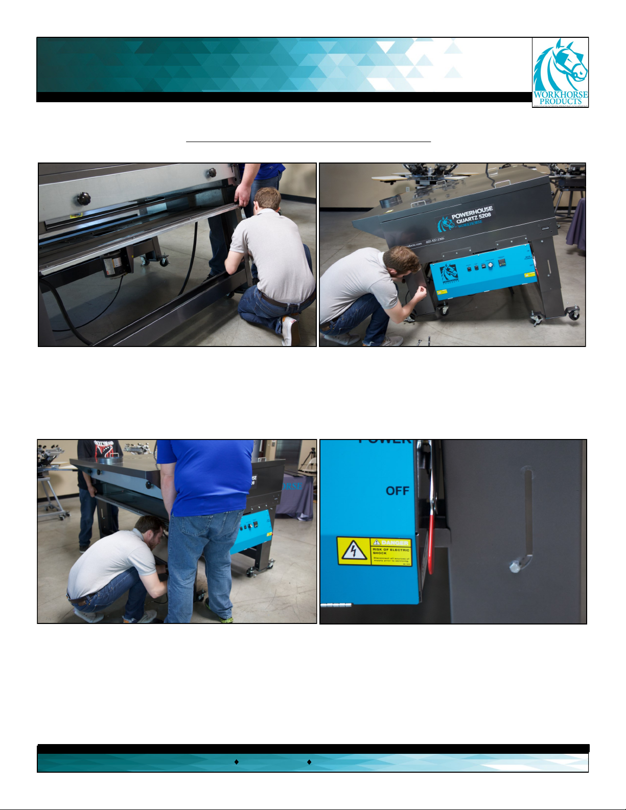
WARNING!
RISK OF ELECTRICAL SHOCK! Turn ALL power to unit OFF before service.
All service should be done by or under the supervision of a trained technician
1. For your safety, do not store or use gasoline or other ammable vapors and liquids in the vicinity (at least 3’ (1 Meter)) of this or
any other appliance.
2. Vent lines to the outdoors must be installed by a qualied HVAC engineer on all air exhaust and gas line components equipped
with a vent ng.
3. Proper grounding (a ground rod at the equipment foong), according to NEC requirements, must be provided for during
electrical connecon by a QUALIFIED ELECTRICIAN.
4. Never alter the internal wiring of this machine.
5. Never place any item other than the stock to be cured or dried on this dryer’s conveyor belt. Do not overload the belt.
6. Do not let the conveyor belt track o the conveyor drive rollers.
7. Keep all loose arcles (including clothing, hair, jewelry, etc.) away from the conveyor belt.
8. Never leave the machine unaended when it is operang.
9. Do not perform maintenance on this machine unl all power has been shut o at the dryer AND at the incoming power circuit
breaker.
THIS ELECTRIC DRYER IS INTENDED SOLELY FOR THE PURPOSE OF CURING INK ON TEXTILE AND CUT GOODS. THIS
DRYER IS NOT INTENDED FOR USE IN HEATING, CURING OR BAKING OF ANY OTHER MATERIALS.
THIS DRYER IS INTENDED FOR INDOOR USE ONLY
THE EXCLAMATION WITHIN AN EQUILATERAL TRIANGLE SYMBOL IS INTENDED TO ALERT THE USER
OF IMPORTANT SAFETY PRECAUTIONS TO BE AWARE OF DURING OPERATION.

Assembly
3730 E. Southern Avenue, Phoenix, AZ 85040 USA
800-778-8779 Workhorseproducts.com 7
Step 1: Leveling the dryer and installing the legs.
Tools needed:
9/16” Socket
Wrench
9/16” Wrench
Parts needed:
Dryer Base
8 x Lock Washers
1. Install a hex bolt into the “J” located on the leg,
which is on the pre-assembled base.
2. Thread a lock nut onto the other side of the bolt,
which is located inside of the dryer. Make sure the nut
is very loose, because the bolt has to be able to move
when the base is lied.
Repeat steps 1-2 for the other leg on the same side.
3. Using two people, li the dryer to expose the leg.
The bolt will fall to the very boom of the “J” where a
third person will ghten it. Use a 9/16” socket wrench
on the bolt and a 9/16” wrench on the nut.
The two people holding the dryer will connue holding
the same side up, so the third person can repeat steps
1 and 2 for the other leg on the same side.
8 x Flat Washers
12 x Hex Bolts (5/16-
18” x 3/4”)
12 x Flange Nuts

Assembly
3730 E. Southern Avenue, Phoenix, AZ 85040 USA
800-778-8779 Workhorseproducts.com 8
Step 1 (Connued): Leveling the dryer.
4. With the side of the dryer sll lied, ghten the bolt
and nut for the other leg.
5. At this point, only one side of the dryer will be
leveled. Just like steps 1-2, insert a bolt and nut
loosely into the “J”.
6. With two people liing, let the bolt fall to the
boom of the “J” and the third person ghtens the nut
and bolt with a socket wrench and a wrench.
Insert the bolt and nut into the other side while the
dryer is sll lied. Tighten the last leg.
7. The dryer is leveled aer all four legs
have been ghtened. The bolt should be at
the boom of the “J”, just like in the photo
above.

Assembly
3730 E. Southern Avenue, Phoenix, AZ 85040 USA
800-778-8779 Workhorseproducts.com 9
Step 1 (Connued): Installing the legs.
8. Insert a 1/2” washer, lock washer and hex bolt
(5/16-18”x 3/4”) into the side panel on the side of
the leg.
9. Tighten a 5/16” ange nut onto the other side of
the bolt located inside of the dryer. Tighten the bolt
and nut with a socket wrench and wrench. Repeat
steps 8-9 for the other side panel on the same leg.
10. Repeat steps 8-9 for the other three legs. In total
eight holes should be lled with the designated nut
and bolt.
11. At this point the legs should match the photo
above. The “J” and the two side panels should be
installed for every leg.

Assembly
3730 E. Southern Avenue, Phoenix, AZ 85040 USA
800-778-8779 Workhorseproducts.com 10
Step 2: Aaching the support struts.
Tools needed:
7/16” Wrench
7/16” Socket
Parts needed:
2 x Support Struts
4 x Hex Bolts
(5/16-18” x 3/4”)
1. Remove the bolt at the boom of the “J” using a
7/16” socket wrench.
2. Align a support strut with the hole at the boom of
the “J” where the bolt originally was, and the second
hole below it.
3. Reinsert the hex bolt with a
lock washer and at washer
into its original posion at the
boom of the “J”, which will be
the top of the strut.
4. Tighten a ange nut onto the other
side of the bolt located in side of the
dryer. Install the other hole on the
boom of the strut. Then install the
other end to fully install the strut.
5. Repeat steps 1-4 to install the
other strut onto the other side of
the dryer. There should be a strut
on the front side and the back side
of the dryer.
4 x Lock Washers
4 x Flat Washers
4 x Flange Nuts

Assembly
3730 E. Southern Avenue, Phoenix, AZ 85040 USA
800-778-8779 Workhorseproducts.com 11
Step 3: Aaching the oueed.
Parts needed:
Oueed Arm
8 x Hex Bolt (1/4-20 x 1/2”)
8 x Flat Washers
Tools needed:
7/16” Socket
Wrench
1. The oueed arm (with the belt motor) belongs on the
le side of the dryer. With another person, li the arm
and slide it into the dryer while aligning the four holes.
2. While sll holding the oueed arm, thread a hex bolt
(1/4-20 x 1/2”) with a at washer into all four of the
holes.
3. Tighten all four holes with a 7/16” socket wrench.
Repeat steps 1-3 for the other side of the arm on the
other side of the dryer.

Assembly
Step 4: Aaching the infeed.
Parts needed:
Infeed Arm
8 x Hex Boles (1/4-20 x 1/2”)
8 x Flat Washers
Tools needed:
7/16” Socket
Wrench
1. The infeed arm (without the belt motor) belongs on
the right side of the dryer. With another person, li the
arm and slide it into the dryer while aligning the four
holes.
2. While sll holding the infeed arm, thread a hex bolt
(1/4-20 x 1/2”) with a at washer into all four of the
holes.
3. Tighten all four holes with a 7/16” socket wrench.
Repeat steps 1-3 for the other side of the arm on the
other side of the dryer.
3730 E. Southern Avenue, Phoenix, AZ 85040 USA
800-778-8779 Workhorseproducts.com 12

Assembly
3730 E. Southern Avenue, Phoenix, AZ 85040 USA
800-778-8779 Workhorseproducts.com 13
Step 5: Installing the belt.
Parts needed:
Belt
Threading Pin
1. Thread the belt over the top of the oueed roller and
over the upper cross brace. Aer the belt has gone
through the chamber, pull the belt to hang over the
infeed roller to add weight to help with the threading of
the lower poron.
2. On the oueed side, take the other end of the belt and
thread it under the oueed roller and under the lower cross
brace, through the lower slot on the roller/rail assembly.
Guide the belt through the oven chamber so it connues
through the lower slot and over the lower cross brace.
3. Thread the belt unl both ends
meet on the infeed roller.
4. To install the belt it may be required
to adjust the belt tracking. This is done
by turning the tension bolt clockwise
(to ghten) or counterclockwise (to
loosen). Belt tracking will be explained
more in-depth on page 13.
5. Align the belt closure unl the teeth
mesh connect, and install the threading
pin into the teeth. Hold together the
teeth while installing the pin. When it’s
fully inserted and the belt is fully in-
stalled, trim any extra pin that may be
jung from the sides.

Assembly
3730 E. Southern Avenue, Phoenix, AZ 85040 USA
800-778-8779 Workhorseproducts.com 14
Step 6: Adjusng the belt tracking system.
Aer the belt is centered on the rubber poron of the rollers, evenly adjust the tension bolts on every
corner of the dryer to ghten the belt unl it can be deected by about 2 inches. Turn the dryer on and
set the belt speed to 35%, as the belt moves make small adjustments to maintain the belt to be in the
center of the rollers. Turn the tension bolts clockwise to ghten the belt in that corner, or turn the bolt
counter-clockwise to loosen the belt in that corner.
If the belt is tracking to the right, turn the tension bolt clockwise in 1/4 increments.
If the belt is tracking to the le, turn the tension bolt clockwise in 1/4 increments.
Connue using the right and le tension bolts unl the belt is centered.
Adjusng the belt to be centered is crical to prevent premature wear of the motor and the belt. In cases
where too much belt tracking has caused the belt to become too tense, it is necessary to reset the tension
bolts and start over. DO NOT OVER TENSION THE BELT.

Assembly
3730 E. Southern Avenue, Phoenix, AZ 85040 USA
800-778-8779 Workhorseproducts.com 15
Step 7: Installing the reectors.
Tools Needed:
7/16” Socket
Wrench
Parts Needed:
6 x Heat Reectors
8 x Hex HD Bolt (1/4-20” x 2-1/2”)
8 x Flat Washers
1. With another person, li the covers
to expose the quartz elements. Remove
all of the packaging and insulaon o
of the elements, because they could be
a potenal re hazard. DO NOT TOUCH
THE ELEMENTS.
2. Place a reector over every element.
The element ts into the notches that
are on the sides of the dryer.
3. Place all six reectors over all six
elements.
4. With another person place the
covers back on top of the dryer.
5. Insert a hex bolt (1/4-20” x 2-1/2”)
and a washer into all eight holes on
the cover.
6. Tighten all eight bolts with a 7/16”
socket wrench.

Assembly
3730 E. Southern Avenue, Phoenix, AZ 85040 USA
800-778-8779 Workhorseproducts.com 16
Step 8: Connecng to the engine.
1. Connect the wire of the belt motor to the wire
of the engine.
Congratulaons! The Powerhouse Quartz Dryer is
now fully assembled!
The size and specifications of the electrical connections made during installation MUST BE DETERMINED BY
A LICENSED ELECTRICIAN. FOLLOW ALL LOCAL BUILDING AND PLANNING CODES. Failure to do so may re-
sult in damage to the unit, building, or cause serious injury.
Before any electrical connections are made verify all safety precautions have been taken to ensure the safety
of all shop personnel. The dedicated breaker providing power to the dryer MUST BE OFF, AND USE OF A SER-
VICE LOCKOUT TAG IS REQUIRED. This will prevent anyone from turning on the power as the connections are
being made. After all safety precautions have been taken the electrical connections can be made. All electrical
connections must be made by a licensed electrician. Refer to factory specifications for proper installation.

Elements
3730 E. Southern Avenue, Phoenix, AZ 85040 USA
800-778-8779 Workhorseproducts.com 17
The quartz elements are installed using a ring terminal system. Fasten the elements securely to the buss bars
using KEPS nuts as shown in Image 1.
Image 1 Image 2
Image 2 shows the opposite side of the elements, mounted in a similar manner.
When installing new elements it may be necessary to adjust the buss bar spacing. Loosen the 2 center nuts
on the insulator plate in Image 2 to adjust the buss bar accordingly.
ALL HARDWARE MUST BE SECURELY FASTENED TO ENSURE PROPER CONTACT AND PREVENT DAMAGE TO THE
ELEMENTS OR THE DRYER.
Dryer Element Count Voltage Waage each
PHQ-2608 6 230V 1400
PHQ-3011 12 230V 1000
PHQ-4013 12 230V 1000
PHQ-5208 6 230V 1700
PHQ-5217 16 230V 1700

Controls
3730 E. Southern Avenue, Phoenix, AZ 85040 USA
800-778-8779 Workhorseproducts.com 18
123456
Before turning the dryer on make sure that the belt is empty and all of the switches on the front panel are
in the o posion.
1. Heaters: Turns on/o the quartz elements that are located inside of the dryer.
2. Flash: Turns on 2 to 4 (depending on the dryer model) elements for a quick burst of heat as the garments enter the
dryer.
3. FWD/REV: Controls the direcon of the belt. This may aect the belt tracking and addional adjustments may be
needed to maintain proper belt tracking when changing the direcon of belt travel.
4. Conveyor Speed: Controls the speed of the belt based on a percentage scale. For example, seng the knob at 40
means the belt is running at 40% of the maximum output voltage of 90 VDC. This is the factory recommended ini-
al speed seng.
5. Temperature Control: The digital temperature control regulates the oven chamber temperature. The duel display
shows both the current (red) and set temperature (green). When the dryer is coming up to temperature a small
green indicator light labeled “OUT” will be illuminated. The factory recommended inial temperature seng is 310
degrees Fahrenheit. See page 28-29 for detailed funcons.
6. Main Disconnect: Controls the main input power to the dryer. When the main disconnect for the dryer is turned
on (red handle up) the belt, recirculaon motor, cooling motor and temperature control may be operator.
When turning o the dryer, turn the “HEATERS” switch o rst. Allowing the belt to run for 10 to 15 minutes with
the elements o will allow the oven chamber to gradually cool down. Failure to follow this procedure may result in
damage to the dryer and may pose a re hazard.
Always check garment and ink manufacturers guidelines for proper garment curing and temperatures.
Please note that the actual temperature displayed by the controller is not the temperature of the garments in the oven
chamber. The surface temperature of the garments may be signicantly higher than the actual oven chamber tempera-
ture. Workhorse Products carries a non contact infrared digital thermometer to accurately measure the surface tem-
perature of your garments. Please call customer service today for price and availability!

Recirculaon System
3730 E. Southern Avenue, Phoenix, AZ 85040 USA
800-778-8779 Workhorseproducts.com 19
All Powerhouse Quartz Dryers are equipped with an air recirculaon system to convert radiant heat to con-
vecon heat. Convecon heat is ideal for garment curing as it completely envelopes the garment and cures
the ink more evenly.
The diagram above shows the path of the circulang air. Drawn thru a center mounted blower motor the air
is pushed through internal air chambers and down through the quartz element banks. The radiant heat from
the elements is now transferred into the air converng it into convecon heat.
General use of the dryer will cause lint and
debris from garments and the surrounding
atmosphere to collect inside the internal air
chambers. Locate the blower motor mount-
ed externally on the boom of the heat
chamber. Remove the two screws securing
the motor mount. The motor assembly will
swing out of the way allowing the removal
of any lint or debris from the blower wheel
and internal air chambers.
Workhorse Products recommends performing this roune maintenance every three to six
months to maintain opmum performance of your dryer.

Venlaon
3730 E. Southern Avenue, Phoenix, AZ 85040 USA
800-778-8779 Workhorseproducts.com 20
A venlaon hood has been Installed on the factory out-feed side of the dryer. This can be
connected to a standard duct line vented to the outside of the building. For longer duct lines
to the outside of the building or if local building codes require roof top venlaon, inline duct
boosters may be used.
An addional hood may also be installed on the infeed side of the dryer. It is recommended
that the venlaon system is professionally installed in compliance to all local building codes
to ensure the safety of all shop personnel.
Please call Workhorse Products Customer Service today for price and availability!
Table of contents
Other Workhorse Dryer manuals
Popular Dryer manuals by other brands

Intelligent
Intelligent EcoForce user manual

Whirlpool
Whirlpool 7MWGD1860EM0 installation instructions

Whirlpool
Whirlpool W10678945D Use & care guide

Alliance Laundry Systems
Alliance Laundry Systems UA025L manual

Samsung
Samsung DV520AE-02836A-01 user manual

Frigidaire
Frigidaire GLEQ2152EE0 installation instructions

Admiral
Admiral AED4675YQ1 installation instructions

Geesa
Geesa PUBLIC AREA 6453-02 instruction manual

Baumatic
Baumatic BFVTD6BL instruction manual

Vox
Vox THP920T2TA user manual

Alliance Laundry Systems
Alliance Laundry Systems DRY710C Installation & operation

GE
GE Electric Dryer 02 installation instructions