manuals.online logo
Brands
  1. Home
  2. •
  3. Brands
  4. •
  5. World Cat
  6. •
  7. Boat
  8. •
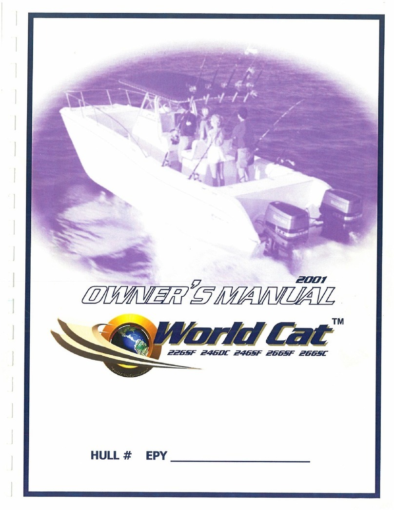
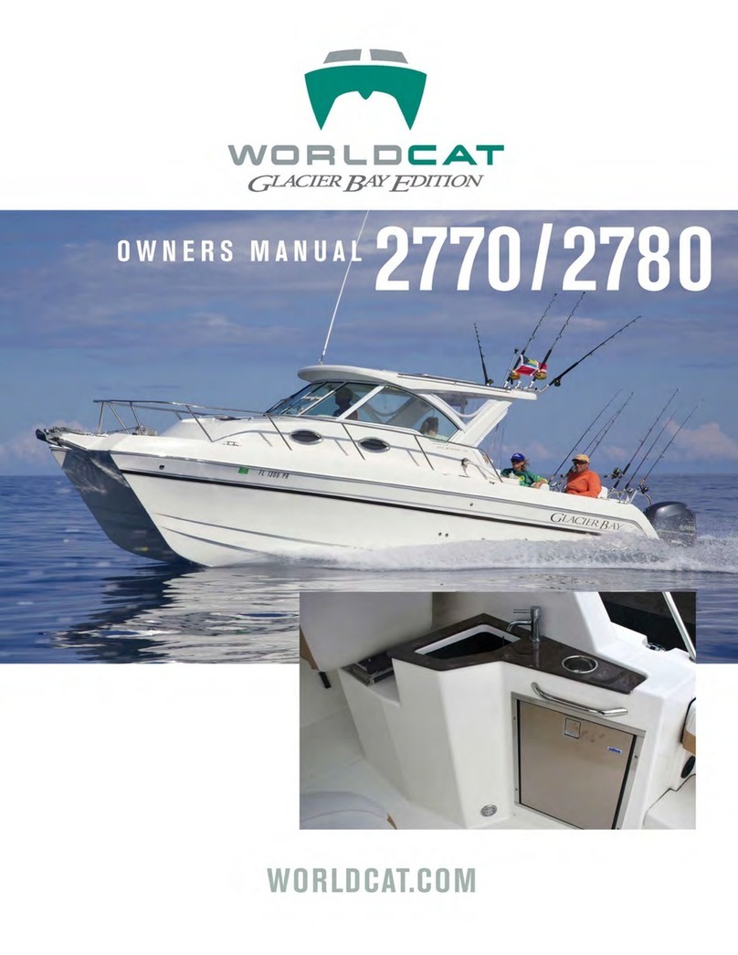
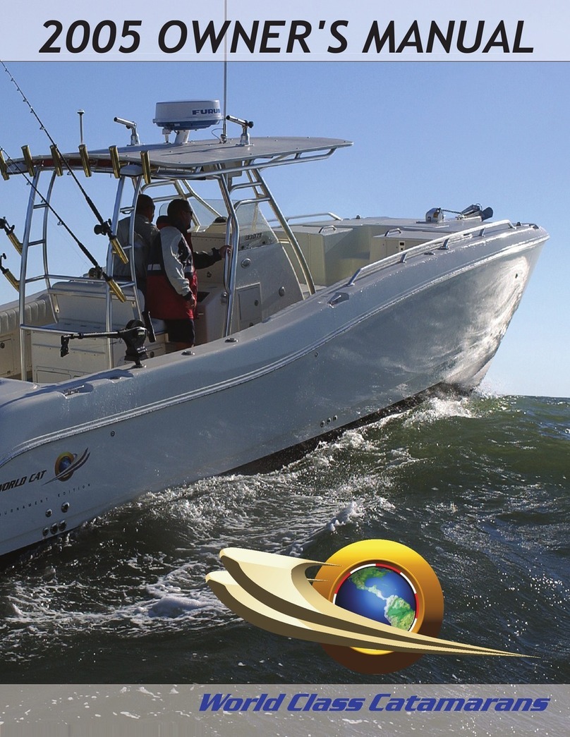
  9. World Cat 246SF 1998 User manual

World Cat 246SF 1998 User manual

]
]
]
]
1
1
J
1
1
]
J
J
J
J
J
J
•
I
/19'il
TM
WORLD CAT
OWNERS MANUAL
TABLE OF CONTENTS
WELCOME!
i
OWNER SATISFACTION MESSAGE Ii
LIM ITED WARRANTY STATEMENT 1
COMPONENTS SUPPLIER LIST 2
ADVISORY LABELS 3
CARE
&
GENERAL INFORMATION ,' 4 - 5
RIGGING GUIDELINES 6
STEERING SySTEM 7-8
FUEL SYSTEM (all models) 9
FRESH and RAW WATER SYSTEMS 10 - 12
BAITWELL SYSTEM 13
ELECTRICAL SYSTEM & BATTERY INFORMATION 14
WIRING CODE ' 15
GAUGE TROUBLESHOOTING QUICK REFERENCE 16
INSTRUMENTATION DATA 17 - 20
DETAILS OF SWITCH WIRING 21 .22
SWITCH
and
INSTRUMENT PANEL DIAGRAMS 23 - 34
WI NDLASS WI RING DIAGRAM _ 35
WINDLASS OPERATION & MAINTENANCE 36.37
TRAILER BRAKE REQUI REMENTS 38
TM
FOR FURTHER INFORMATION, CONTACT YOUR
WORLD CAT
DEALER, OR:
WCC GROUP, INC.
ATTN: CUSTOMER SERVICE
801 STATON RD.
GREENVILLE, NC
919/754-1948
FAX 919/754-1949
e-mail [email protected]
https://www.boat-manuals.com/world-cat/
wee
Group, Inc.
World Cat Limited Warranty
WARRANTY COVERAGE
]
]
]
]
WCC Group, Inc. (hereinafter referred to as the Manufacturer) warrants to the original purchaser, or approved transferee, that the boat, and all
COf!'po"e~ts a~d accessories rroanufact~red by the Manufacturer shall be free from defects in materials and wori<manship for a period of one
(1)
year frcm
the date of original purchase, and further, that the hull and deck will be free from structural defects caused by faulty materials or workmanship for a period
of five (5) years from the date of original purchase from the Manufaclure~s authorized dealer. It is further warranted thai the gelcoat surface of the hull
bottom will be free from blistering that may occur as a result of defects in materials and workmanship for a period of five (5) years from the date of original
purchase from an authorized dealer, provided that the gelcoat surface has not been altered in any way such as sanding or sandblasting, or the application
of a coating other than a standard type of anti-fouling paint and primer coating, Which will void this warranty provision. Products that are proven to be
defective within the applicable warranty period, when used and maintained according to the manufaclure~s instructions, will be repaired or replaced by the
1
Manufacturer, or one of its authorized dealers, at the option of the Manufacturer, and only after prior authorization of the Manufacturer. All warranty
claims in excess of
$
200.00 may require substantiation prior to authorization, at the option of the Manufacturer. This warranty may be transferred by
following the procedures in the Owne~s Manual. This warranty provides specifi6 legal rights; other rights may be applicable according to local statutes.
LIMITATIONS
1
1
Warranty coverage does not extend to any Purchaser other than the original purchaser from the Manufacture~s auL'lorized dealer, or an approved
L'1lnsferee. Warranty coverage does not include:
1.
Outboard motors, propellers, balleries, anti-fouling paint or any component or accessory not manufactured by the Manufacturer. Reier to the
Owne~s Manual for specific warranty details on components and accessories.
2. Gelcoat cracking, crazing or discoloration.
J
3. Damage caused by misuse or a~use, racing, storm damage, grounding, commercial use of the boat, or norma! dete~oration.
4. Upholstery damage or deterioration.
5. Damage or deterioration resulting from environmental conditions.
1
6. MY
repairs, adjustments or modifications to a boat or any of its components made by anyone ether than an employee of WCC Group, Inc.
7. Damage which has occumed as a result of the boat being operated as a demonstrator and/or displayed for sale.
8. Damage or deterioration of the boat or its components due to altachment
01
hardware or other componenls by anyone other than an employee of the
Manufacturer.
1
Repair or replacemenl, at the option
01
the Manufacturer, is the exclusive remedy under this warranty; in no event shall the Manufacturer be liable for any
consequential or incidental damages, including, but not limited
10,
telephone. food, lodging, or charges for transportation or hauling out in order
(0
effect
J
warranty repair, unless provided for under local statute, in which case these exclusions may not be applicable. TO THE EXTENT ALLOWED 8Y LAW,
ANY AND ALL IMPLIED WARRANTIES, INCLUDING THE IMPLIED WARRANTY OF MERCHANTIBILITY AND ANY APPLICABLE IMPLIED
WARRANTY OF FITNESS FOR A PARTICULAR PURPOSE ARE LIMiTED TO THE DURATION OF THIS WARRANTY, UNLESS PRESCRI8ED 8Y
LOCAL STATUTE. The rights and obligations of the Perohaser and the Manufacturer under this written warranty rray not be varied or modined.
J
RESPONSIBILITY OF THE PURCHASER
J
1.
This warranty extends ONLY TO THE ORIGINAL PURCHASER OR AN APPROVED TRANSFEREE ON THE CONDITION the cwner completes and
maiis the warranty card to WCC Group. Inc., Warranty Registralion, 801 Staton Rd., Greenville. NC 27834 wilhin fifteen (15) days after laking
delivery of the boat.
2. The original purchaser or approved transferee must give WRITTEN NOTICE of the claimed defecl to an authorized dealer within
I
fifteen (15) days after first detecting the claimed defect. It must appear to the ManL1acturer's reasonable satisfaction that the c:aimed defect is
covered by warranty. Purchaser must give WRITTEN NOTICE to WCC Group, Inc., Warranty Claims, of any failure by an autho,;zed
dealer to respond
10
a claimed defect within fifteen (15) days after first notification te the autherized dealer.
3. The boat, including any claimed defective part, MUST be relumed to an aulhorized dealer for the Manufacturer (or elsew~ere, as directed by the
I
Manufacturer) withir the warranty period for inspection and warranty service. ALL EXPENSES incurred in retuming the ~oat to the authorized
dealer and back to t.'ceowner will be paid by the owner.
THIS FORM MUST BE COMPLETED AND SIGNED AT THE TIME OF DELIVERY AND THE APPROPRIATE COPIES RETURNED IMMEDIATELY TO
FACILITATE THE HANDLING OF ANY CLAIM THAT MAY ARISE UNDER THE TERMS OF THIS LIMITED WARRANTY AND TO COMPLY WITH THE
FEDERAl BOAT!NG SAFETY ACT OF 1971.
WCC Group, Inc. reserves the right to modify its products t.~rough changes in design and/or material without no lice and without obligation to the owners
01
similar and/or same models of prior manufacture. We may be contacted at WCC Group. Inc., Cuslomer Service, 801 Staton Rd., Greenville, NC
27834.
-1-
https://www.boat-manuals.com/world-cat/
]
]
]
]
]
]
]
1
1
]
]
J
I
I
I
I
WORLD CAT
COMPONENTS SUPPLIER LIST
SUPPLIER PRODUCI(S) WARRANTY TELEPHONE #
A.J. Canvas Enclosures 1 yr. Contact WCC
Armstrong Nautical Products Bow Pulpit & Swim Ladder 3 yrs. 800/226-7204
Aqua Power (Morse) Fuel Filters 1 yr. 800/404-3951
Atlantic Marine Products Electrical Panels 1 yr. 757/498-4195
Bomar Cabin & Console Portlights 1 yr. 603/826-5791
Crane Interiors All UphOlstery 2 yrs. Contact WCC
Custom Marine Fabrication Cabin & Console Tops Stainless - 5 yrs.
Aluminum - 2 yrs. 919/638-2920
Dura-Cast Fresh Water tank 1 yr. 800/683-4116
Faria Gauges Gauges 1 yr. 800/473-2742
Florida Marine Tanks Fuel Tanks 1 yr. Contact WCC
Inca MOlded Products Baitwell 1 yr. 615/350-7290
Lewmar Marine Cabin Hatch, Windlass 3 yrs. 203/458-6200
New Century Products Cabin Windshield 1 yr. 615/822-2001
Rule Industries Bilge Pumps 5 yrs., pro-rated 978/281-0440
Rule Industries (dlv.) Danforth Compass 3 yrs. 978/281-0440
Scandvik Washdown Faucet
&
Shower 1 yr. 800/535-6009
ShurFlo Water Pumps & Cabin Faucet 1 yr. 800/854-3218
Tampco Bow Rail
1
yr.
910/835-1895
Teleflex Hydraulic Steering 2 yrs. 604/270-6899
Thetford Porta-Potti 1 yr. 800/354-4135
Note: Contact the listed vendor for component replacement. Most parts will have the
manufacturer's name located somewhere on the part. Please attempt to be certain the
vendor that you contact is the supplier of the part required, or see your dealer.
,.p..
..•
:
., j
iI
-2-
https://www.boat-manuals.com/world-cat/

AUVI~UKYLAl:icL~
.A.
WARNING
AVOID SERIOUS OR FATAL INJURY
DO NOT OCCUpy FORWARD SEATS
WHILE UNDERWAY
A.
CAUTION
TORQUE ENGINE MOUNTING BOLTS TO 40 FT.LBS.
(4.56Kgm.) ONLY RE-TORQUE PERIODICALLY,
BUT AT LEAST ANNUALLY
A.
DANGER
STOP ENGINES BEFORE USE
OF BOARDING LADDER.
A
WARNING
Do Not Leave Battery Switch In On Position
When Both Engines Are Running
A
WARNING
LEAKING FUEL IS A FIRE & EXPLOSION HAZARD.
INSPECT FUEL SYSTEM REGULARLY FOR LEAKS
&
CORROSION. BUT AT LEAST ANNUALLY
266 sc ONLY
Bow Area Seating
ALL MODELS
Transom Area
(2 installed)
ALL MODELS
After Bulkhead
ALL MODELS
Starboard Battery
Compartment
ALL MODELS
Starboard Battery
Compart
t":14
nt
-3-
https://www.boat-manuals.com/world-cat/

1
1
I
1
1
1
]
]
J
J
I
j
J
J
l
I
-.
CARE, CLEANING
&
GENERAL INFORMATION
Some simple maintenance tasks performed on a regular basis will keep your WORLD CAT in to;!
condition. Eve~ if you are a seasoned skipper, we suggest that you spend a few minutes reviewing the
following information. If you have further questions, talk with your dealer for specific recommendations.
GENERAL CARE
The gelcoat surface of your boat is the best available, and is fonmulated to resist UV degradation for
many years. However, accumulated dirt and mineral deposits will cause the finish to lose that
"showroom" look more rapidly. Regular washdowns with fresh water and the use of a mild detergent,
such as Ivory liquid, will eXtend that new boat look. In addition, an occasional coat of marine paste wax
will further protect all surfaces. Use of harsh chemical or abrasive cleaners is
1lQ1
recommended.
STAINLESS STEEL
Contrary to popular belief, stainless steel is not "stainless." Without proper care, it can rust and discolor
gelcoat surfaces (bleeding). Regular washdowns with fresh water and detergent will lessen that
possibility. Occasional waxing or wiping down with a product such as Corrosion.X will protect the
stainless steel components. NEVER USE STEEL WOOL on rusted areas. It will scratch the protective
surface, causing irreparable damage. Avoid the use of any product not specifically designed for use on
stainless steel, and check to make certain that other nearby surfaces will not be damaged through such
use. For further infonmation, refer to the care pamphlet included with this Manual.
SUNBRELLA
Sunbrella should be cleaned regularly before dirt and mineral deposits become embedded in the fabric.
Lightly soiled Sunbrella can be cleaned without removal from the installation. Brush off loose dirt, etc.,
wet down with fresh water and clean with a mild solution of Ivory liquid and lukewarm water.
For heavily soiled fabric, removal from the frame is necessary. Soak in a solution of 1/2 cup of
household bleach and 1/4 cup of Ivory liquid soap per gallon of lukewanm water. Allow the fabric to soak
until the bleach has killed any mildew and the stains can be brushed out with a soft bristle kitchen scrub
brush. Rinse the fabric repeatedly in cold water to remove soap residue. Allow the fabric to AIR DRY
completely before re.installing.
NEVER store any Sunbrella while wet or dirty, or in a moist unventilated area. ALWAYS roll the fabric
instead of folding, particularly on side curtains with clear plastic windows. Roll Birr:ini teps carefully
around the collapsed bows and cover with the storage boot. .
ZIPPERS & SNAPS
Occasional light lubrication with Corrosion.X will keep these parts operating smoothly. Avoid spraying
lubricant on adjacent fabric or acrylic surfaces.
CLEAR ACRYLIC
&
VINYL WINDOWS
&
PORTS
Clean with a mild solution of Ivory liquid soap and lukewarm water, using a soft cloth. Use of Pledge
fumiture polish (NOT lemon-scented) will extend the life of flexible clear vinyl and prevent shrinkage. If
scratched, use a product made for clear acrylic scratch removal. Use of automotive products such as
Armorall may penmanently cloud the surface.
INTERIOR CUSHIONS
Brush and/or vacuum to remove loose dirt. Heavier accum~lations may be removed with a mild solution
of WOOL~e and lukewarm water, applying the foam only with a soft brush. Remove dirt by wiping lightly< _.'
with a dry cotton towel. Allow thorough AIR DRYING before placing cushions back in the cabin..
-4-
https://www.boat-manuals.com/world-cat/
l
]
l
,
Regular washing with a solution of water and Ivory liquid as part of general boat care is recommendea.
Exterior cushions are closed-cell foam, which will not absorb water. Use a protecti,e product specifically
formulated for marine vinyl to provide UV protection. Use of automotive products such as Armorall may
deteriorate surfaces and shorten fabric life.
FRESH WATER TANK
Cleaning or deodorizing the fresh water tank may be accomplished by filling the lank with a 5% solution
of household bleach and water after draining the contents of the tank. Add approximately 10 gal. water,
then add 1 gal. bleach - fill the remainder of the tank with water. Let stand for several hours. Drain the
tank, refill and drain repeatedly until all chlorine odor is removed.
WINTERIZA TIONlLA Y-UP
Refer to the motor manufacturer's manual for storage instructions. Drain all fresh and raw water tanks.
Remove batteries and store in a dry cool area (not on a cement surface); maintain charge levels with a
trickle-charger. Drain fuel tanks, or fill completely as per local practice or regulation. If full tanks are
stored for more than 30 days, it is recommended that a fuel stabilizer be added to prevent degradation.
Remove all personal items and portable electronics. Wash the boat thoroughly with a solution of fresh
water and Ivory liquid and apply a coat of marine paste wax. If covering, provide some means of
ventilation to prevent moisture and/or heat damage.
BOTTOM PAINTING
If your WORLD CAT is to be left in the water for extended periods, it is recommended that an application
of a high-quality bottom paint be applied to protect against marine growth and deteriorated performance.
Follow all manufacturer's precautions regarding the use of personal protective equipment, etc. Hint: To
establish the waterline for masking, put the boat in the water for a few days to establish a "scum line" and
mask off accordingly. Prepare the hulls by removal of mold release waxes, wiping down the surfaces
with a pre.primer solvent; change application and removal rags frequently. Scratch the surfaces lightly
with a Scotch-Brite pad to provide a footing for the primer coat. Wipe lightly with solvent once again.
Apply an epoxy barrier prime coat(s) per the manufacturer's instructions. Apply the final coat(s) of
bottom paint and re-Iaunch per instructions.
L1FTlNGIDRY-5TACK STORAGE
The WORLD CA Tmay be lifted and stored through the use of the (optional) bow lifting eye and lhe dual
transom eyes. Use a spreader bar at the stem to prevent damage to the outboard motors. Slings may
also be used, taking care to support at the stem just aft of the fish box and forward at least at the front of
the console or the cabin windshield area. Lifting the boat with a forklift may be accomplished through the
use of slings, with a supportive lifting platform (see your dealer) or through the center of the tunnel, if the
forks can be collapsed sufficiently. Because of the rounded bottom of the hulls and the narrow chines, it
is specifically recommended that your dry stack operalor NOT attempt to lift the
World Cat
from the
outside of each hull.
TRANSDUCERS
Transducer mounting is more difficult on a power cat due to the narrow hulls requiring a transom
mounting point near the outboards; a possible cavitation problem may result. With the advent of higher
power transducers, it is possible to mount them inside the bilge at the bottom, just forward of the bilge
pumps, using a product such as epoxy or 3M 5200 sealant -- not silicone (refer to the manufacturer's
instructions). For tri-ducer installations (depth, temp, speed), through-hull is best if the boat will not be
trailered, again forward of the pumps.
-5-
https://www.boat-manuals.com/world-cat/
J
]
]
]
]
]
]
]
J
J
J
J
I
~
J
J
1
j
,
WUHLU l:AI
RIGGING INFORMATION
Note: These are general recommendations for the proper rigging of a World Cal. In ill! cases, however,
the experience of the installation technician regarding safe procedures should prevail.
Motor Mounting
Transoms are pre-drilled during production to allow for proper motor mounting.
Transom height is 261/4", requiring the use of x-long shaft (25") motors. The installation height will be
slightly higher than on a conventional monohull to allow cavitation to occur within reasonable limits to
provide the best acceleration. Generally, the cavitation plate height is the best reference to determine
which bolt hole to use - the plate should be
3/4" -
1" above the bottom (splitting the drain plug hole).
Higher installations may require the use of low water pickups to prevent overheating and may also result
in premature blow-out of the props; therefore, extreme mounting heights are not recommended. Motor
mounting bolts should be torque to 40 ft. Ibs. (4.56Kgm) ONLY. Re-torque mounting bolts periodically,
but at least annually.
Motor Toe
It is recommended that the relationship between the two motors' direction of thrust (toe) be
set at zero to achieve the lightest steering effort and best performance. To adjust toe. refer to the
steering adjustment section below.
Steering Adjustment
The Sea Star dual cylinder hydraulic steering system features a "liquid
tie-bar" to allow both motors to respond to the helm in unison. (Refer to the diagrams in this manual)
Occasionally. it will be necessary to realign the motors due to
nomnal
use. To align the motors, first
center the starboard motor by tuming the helm. Then, open the system ball valve (located beneath the
inspection port on the dive platfomn) by turning it 90 degrees. This will isolate tr,e port motor from the
system and allow it to be moved manually. Center the port motor by hand, then close the ball valve and
replace the inspection port cover. Note: It may become necessary to purge ("bleed") the hydraulic
system of air from time to time. Refer to the Telenex steering system bleeding ir.s:ructions on the next
page.
Trim Tabs
Setting the trim tabs property will provide uniform steering effort as tile r,elm is turned to
port and starboard. The tabs serve to neutralize the torque effect of the motors on the steering system.
For conventional rotation motors, the tab will be set with the trailing edge approximately
3/16"
to the
right. (The adjustment is the same for both motors if both are standard rotation). If a counter-rotation
motor is installed on the port side, that tab will be set with the trailing edge approximately
3/16"
to the
left.
Tilt Angle
Install the tilt pin slightly out to achieve a neutral (straight up & down) position of the motors
relative to the hulls to reduce any bow steering tendency in the mid-speed range. For Yamaha
installations (no tilt pins), it is recommended te.>trim the motors in no further in than 1 bar on the tiit
gauges.
Propeller Selection
There is a wide variety of OEM and after-market propellers that will provide
excellent performance. Your dealer can give customized re:ommendations based upon your specific
requirements. Generally, stainiess steel props offer better overall performance than aluminum. 80th 3
and 4-blades, full blade area (not semi-cleaver) and cupping perform well on power cats.
-6-
https://www.boat-manuals.com/world-cat/

I
Catamaran Bleeding Instructions
III
.
!!
~~
WX
:
)
]
I
]
]
]
J
J
J
J
I
Refer to the original system owner's r:-:anuals purging instructions and read entire text.
Proceed as follows:
Referencing the cylinder alignment valve installation ,schematic.
- Fill helm with oil and attach filter device/container to helm
- Open valve
- Open bleed fitting #1 and pull cylinder sha~ all the wayan fitting #1 side of cylinder
- Turn steering wheel clockwise until an air free stream of oil comes forth fro", bleed fitting #1
DD NOT ALLOW SHAFT TO MOVE BACK INTO CYLINDER. HOLD WITH HAND TO STOP IT FROM MOVING.
- Close bleed fitting #1
- Open bleed fitting #2 and pull cylinder shaft all t~,eway out on Wing ;;2 side of cylinoer
- Turn steering wheel counter-clockwise until an air free stream of oil comes forth from bleed
fitting #2, then close bleed fitting #2
- Open bleed fitting #3 and pull cylinder shaft all the way out on fitting #3 side of cylincer
- Turn steering wheel counter-clockwise u~til an a'r free stream of oil comes
;o;-:,~
;rcm tleed
fitting #3, then close bleed fitting #3
- Open bleed f:tting #4 and puil cylindar shaft all the way
out
on filting #4 "ide of cyli,.cer
- Turn steering wheel counter-clockwise until an air free stream o~oil comes fortr, from bleed
fitting #4, then close bleed fitting #4
- Turn steering whee! back and forth from r:ardcver to ,"1ardover
2
cc~p!e
cf
L'TiES.
A:igrl
cylir"lcers
ty
PL:1li:--,gcylinder rcd all the way
Ol,.;~
on
:Il€
sa,'lle
side
cr
eac~ ::y;;;-,:e~
a;-c
::::;5e
"'c:ve.
--~
~'
I
,
I
I
J
J
J
I
VAI..VE
______ !J=
"
j;
-7-
https://www.boat-manuals.com/world-cat/
J
]
I
]
]
I
]
]
]
]
J
1
J
..•
]
]
]
]
)
Steering System
Lay -
Out
&
Components. All Models
NOTE: Teleflex requires that all steering system fittings be sealed with
LOCTITE
567 THREAD SEALANT (Part No. 56747). AVOID
PLACING SEALANT ON THE FIRST (LEADING) THREAD AS THE
SYSTEM CAN BECOME CONTAMINATED LEADING TO STEERING
FAILURE. READ INSTRUCTIONS ON TUBE PRIOR TO USE.
I
II
ltt
i
/
ll.
I~ _
.II ,
~~
=t~.
~'F=
VALVE
Quantity Description Part Number Application
1Helm Pump 1.7 Tilt Helm All Models
2OIB Cylinders HC5345 All Models
2 20 ft. Hoses H05120 266sc Only
218 ft. Hoses H05118 246sf
&
266sf
2 pair Bulkhead Fittings HF5512 All Models
7 3 ft. Hoses 664224 All Models
-,
-8-
https://www.boat-manuals.com/world-cat/
J
)
I
I
]
J
)
]
)
J
1
J
,
I
~
J
J
]
j
)
Fuel System
All Models
lid
1
n
I
i
I
Ii
I
=
in!
I'
iil I
III
FUEL TAN<
i
ACCESS FORT
!
FILL
IVENT
I
I
i
I
FeE:'"
:;"NK
ACCESS PORl
FILL
I
VENT
-9-
https://www.boat-manuals.com/world-cat/
J
]
I
I
]
Fresh Water System
Center Consoles
FILL. TOP OF ~
CONSOLE \
jl I
I
I
i!
I'
I~
I
Ii I
II
iI
00
J
20 GAL SUPPLY
VENT
RETRACTABLE
SHOWER OUTLET
PUMP
J
I
]
I
I
I
-10-
https://www.boat-manuals.com/world-cat/
I
,
I
I:
i
I!i
'~ I
U
~OO
,no
~I
RECESSED
FILL / VENT
111~
II
,
,
I,
II
,
I
!
I
,
II
,
I
I
,
I
I
i
I
,
,
I
~
I
I
I
I
II
,
00
I.'
I
(i
I
J
t.""
\.
I
,
-11-
\
11'
j~i~
tJ .
I'
iiI
'0'
1\
,
I'
II.
I!
I
II II!
I
GI
20 GAL. SUPPLY TANK & PUMP
INTERIOR CABIN BULKHEAD
WI ACCESS PANEL
RETRACTABLE
SHOWER OUTLET
SUPPLY LINE PASSES THRU
RIGID PVC TUBE OVER TUNNEL
Fresh Water System
Cuddy Cabin
J
]
]
]
]
]
]
]
]
]
J
J
J
j
'
I
J
]
J
I
https://www.boat-manuals.com/world-cat/
J
]
I~~~
~I
i\
J
Raw Water System lid II
I
WI
,II
All Models
J
-~-,
II
J
~
III III
J
-
---"._-
I-~-
J
1
Ir=iil
1
Ir
l
I
!
I
'I
I:il
-s
OUTLET
~ 1,1
1:1
J
ON CONSOLE
I
II
LJI~
(246SF & 266SF)
.OR.
1/
,
I'
~
,
CABIN WING
,
I
(266SC)
I
I
I,
I
,I
,
I"
i
J"
Ii I
,
,
,
II I
SUPPLY LINE
I
ROUTED THRU
J
II
STARBOARD
I
I
RIGGING TUB:'
1I! I
I
IIIII
I
,I
b
I
I
00 00
0
RAW WATER PUMP ACCESSED THRU
~
I
,I
~
PORT BAITERY HATCH / SUPPLIED
THRU BAITWELL PUMP AND/OR
lib'
IINTAKE STRAIN:'R
SEACOCK (1/4 TURN BALL VALVE)
~
I
I
ACCESSED THRU PORT MOTOR WELL
INSPECTION PORT
~~
...pit.
I
-12-
https://www.boat-manuals.com/world-cat/
-13.
_.
I
I
I~
I
I
~
\1
~
BAIT TANK
'\
\
I
I
BRONZE INTAKE
SEACOCK (1/4 TURN BALL VALVE)
TO WASHDOI'I'N PUMP
(
OVERFLOW DRAIN
(1-1/8" TUBING)------~\
DISCHARGE HEAD
END OF DAY DRAIN 1'1'/REMOTE
CONTROL VALVE (3/4" TUBING)
BaitWell System
All Models
•••
]
]
]
]
J
I
~
~
j
~
j
1
j
https://www.boat-manuals.com/world-cat/
]
]
J
1
~
]
1
J
J
J
The electrical system for each engine is isolated, except in emergencies when the
battery jumper switch may be used to temporarily connect both sides (see below). Main
power forward to the helm is provided by the starboard battery through a #6 gao feed
that is protected with a 30A. in-line fuse in the starboard battery/oil injection tank
compartment. All accessories are supplied by the starboard battery, including the
starboard and port bilge pumps in both manual and automatic modes. CAUTION: If
additional batteries or battery switching devices are installed, ensure that the automatic
side of the bilge pumps (wired independently from the main feed -- see Wiring Code,
p.15) remains directly connected to the battery system.
Battery Parallel Switch
The battery jumper switch is located in the starboard battery/oil injection tank
compartment. Its purpose is to provide a means of temporarily cross-connecting the
port and starboard batteries in parallel to provide starting capability for either engine
should the individual dedicated battery become discharged. The normal switch position
is
OFF
if no cross-connection is necessary to avoid the possibility of diode failure in the
alternators. If it becomes necessary to use the jumper switch, turn it to ON and start
the engine on the discharged side. Turn the switch OFF (normal position) and start the
other side.
Battery Capacity
Use of a series 27 marine battery as a minimum will be sufficient for all but
direct-injection outboards (Ficht/Optimax). Due to the precise voltage and amperage
requirements of the ECM modules, these installations require a minimum of 750 cold
cranking amps/1000 marine cranking amps. Therefore, a larger series 29 battery is
strongly recommended for satisfactory operation. CAUTION: The computer control
systems of many outboard motors continually draw small amounts of current, even
when not running. The batteries may therefore discharge completely
if
the boat is
unused over an extended period (approx. 30 days). In such cases, use of a
maintenance trickle charger is recommended, or optionally, disconnecting the batteries
completely. Disconnection will not harm the control systems.
Battery Connection Warning
Disconnecting and reconnecting the battery while the engine is running by either
removing the battery cable(s) from the battery post(s) will cause an extremely high
voltage variation to be produced on the 12 volt line. This voltage will likely cause
immediate failure of instruments and any equipment which is operating at the time and
may damage the altemators. Less obvious, yet just as destructive are loose, or bad
connections between battery cables and battery posts caused by corrosion and/or
frayed cables. Also included in this category are defective, cracked, or corroded
battery switches and isolators. The possibility of damage is due to the fact that in
almost all battery- started engine applications, the battery acts as a voltage limiter. As
a preventative measure, battery terminals and clamps should be cleaned and tightened
periodically. Cracked, corroded, or otherwise defective battery switches or isolators
should be replaced.
-1
't-
https://www.boat-manuals.com/world-cat/
-
---
_ L-..o .••••••••• .•••••• __ ~
..
l
oooo
ij
.••••
WIRING CODE - ALL MODELS
1
--------
NIA NIA
---- ---.
NIA
NJA
N/A
NJA
-
--
-
-
NIA NIA
NIA NIA
#15
.GAU..G.E BREAKER/FUSE AMPS BREAKER/FUSE
LOCATION
.c.QLQR
GREY
--------
----
---
----_.
----_.-------------_._----------
FUNCTION
INSTRUMENT WIRING:
TACH
_ •• _. "'.' Y'
VYh 6Y
BATTERY TO BATTERY JUMPER RED #4 NONE
NJA
HARNESS MAIN FEED RED #6 30A. FUSE STBD. BATTERY COMPARTMEN'
WINDLASS RED #6 50A. BREAKER STBD. BATTERY COMPARTMEN"
WASHDOWN PUMP BROWN #14 10A. BREAKER PANEL
BILGE PUMP MANUAL (x 2) BROWN #16 SA. FUSE (x 2) STBD. BATTERY COMPARTMEN'
BILGE PUMP AUTO (x 2) BROWNIWHITE STRIPE #16 SA. BREAKER (x 2) PANEL
COCKPITJlNTERIOR LIGHTS BLUE #16 SA. BREAKER PANEL
HORN ORANGEIWHITE STRIPE #16 SA. BREAKER PANEL
WIPER ORANGE/BLACK STRIPE #16 SA. BREAKER PANEL
----
WIPER PARK BLACKIWHITE STRIPE 1116
NJA
NIA
_.-
NAV. LIGHTING GREY #16 SA. BREAKER PANEL
--
ANCHOR LIGHT GREYIWHITE STRIPE #16 SA. BREAKER PANEL
""-
BAITWELL PUMP HROWN #16 10A. BREAKER PANEL
.-
FRESH WATER PUMP BROWNIYEl.LOW STRIPE #16 10A. BREAKER PANEL
--
-~--
-
ALL GROUNDS BLACK #4.6.14.16
NJA
NIA
-------- ---.-
.
---
~
I ----- . . _
VOLTMETER PURPLE (l=ROM iGNITION) #16
---_._.-
------_._-
---- -_._--_._-----
FUEL SENDER PINK #16
f---------.--. __'_" ..__ __ _
INST. LIGHTS BLUE #16
-
---_.~-----_._---
_.
---
IGNITION PURPLE #16
I
NOTE: All factory.installed wiring is tinned copper and conforms to ABYC Yacht specifications.
,
..•.
(Jl
,
I
r
https://www.boat-manuals.com/world-cat/
]
J
~J-\U~c.
J
rl.UUDLC>:lf1UU
IIN\
.
J\
..
IUIL
.
!\
Kl:rcKcNI",C
l
:
JUIUl
:
Observe
Gouge
]
]
]
]
]
J
J
J
J
I
-
J
Sad Oauge
CI ••
mp wa.
too
Tight,
Snug It up
&
Recheck.
aauge
Sticking
12VClltor
Ond Fault
Check Fu •••
ond
Conneotlons
aId
Oauge
Sad Sender
Oauge
Inoperative
YES
Sod
SenderlWire
Connection
Goluge
Reading
Incorrectly
NO
Incorrect or
8~d St'nCt"r
CI ••
nor
Tlght.n
Connection.
Bid Gaug.
-16-
https://www.boat-manuals.com/world-cat/
J
]
I
I
]
J
J
]
~
]
J
j
J
..,
MARINE INSTRUMENTATION -- GENERAL FACTS
Meter Movement Stops
Some marine tachometers have no internal meter stops which therefore
permit 360 degrees of pointer movement. When the ignition is shut off, the
pointer will fall to approximately to the 6 o'clock position. When the ignition is
swiched back on, the pointer will go to zero and then to the correct RPM when
engine is started.
Other models will stop on zero with no power applied, but have the
potential for pegging at the maximum RPM's if the switch on the back of the tach
is between positions.
To remedy this, the engine is started and revved up to RPM's higher than
mid-range. This will allow the tach to re-synchronize itself and operate normally.
The tach can also be shut off, and a magnet used on the face of the lens to
return the pointer to zero. Either of these methods can be used (with switch on
back of the tach in the correct position) to return to normal operation.
Lens Fogging
Most marine instruments have small vents in their cases to a[low a way
out for moisture that finds its way in. It is possible for moist air to be drawn into
vents when the air inside the tachometer or gauge cools down after the
instrument is turned off. The morning sun can draw this moisture up against the
[ens, causing fogging. This same sun will help force the moisture back out of the
instrument as well. Running with the instrument lights "on" can also speed up
moisture removal. Fogging is not abnormal, nor will it harm your instruments,
which are built to withstand a harsh environment.
Radio Transmissions
Some interference (erratic operation) may be noticed on tachometers
during radio transmissions. This will neither damage the instrument nor affect its
accuracy when not transmitting.
-17-
https://www.boat-manuals.com/world-cat/
••
]
J
)
]
]
J
]
]
]
J
]
J
I
•••
J
J
J
J
Operation
Electronic tachometers work by counting pulses generated by the ignition system or alternator. The tach is
hooked up to
+
12VDC , Ground, and one of the signal sources listed above. By selecting the right tach and
setting the switch on the back 10the correct position, you let the tachometer know how many pulses are being
sent per engine revolution. From this information, the tach displays the correct engine speed Instrument part
numbers are located on a label attached to the outside of the case (i.e. TCOOOOA).
Application
4 cycle enaines' The t~ch signal terminal is connected to the negative terminal on the ignition coil orto a
transistorized tach driver circuit connected to the ignition system. This circuit will have a wire (usually gray) for
connection to the tach. The correct tachometer will have a white label on the side indicating which switch
position is for each engine type. This label will include 4, 6, and 8 cylinder engines for positions 1, 2, and 3.
.
,
2 cycle engines' The tach signal temninal is usually connected to the unrectified AC output of the
altematorlJighting coil. Sometimes it is hooked directly to the stator output wire (usually yellow) other times a
gray tach output lead is provided. The correct tach for this appHc3tian will have 3 white label cn the side with
switch positions for 4, 6, 8,
10,
12, or 20 pole alternators.
Calibration
Set up a calibrated "shop tach" or "strobe tach" to monitor the engine's true RPM. Start the engine and (after an
appropriate wamn-up period and with the shift in neutral) increase it's speed to the boat's nomnal cruising RPM
read on the shop tach. Set the coarse adjustment switch to the proper position described on it's label. Remove
the stop-plug or paper label corner (at the B-o'clock position on the rear of the case for most) and insert a 5/16"
Allen wrench into the "fine adjustment" trim pot, rotating it CW or CCW as necessary to indicate the true RPM.
Troubleshooting
Symptom recognition is the first step in effective instrumentation troubleshooting. Tachometers usua!ly exhibit
the following symptoms:
A) ~ - This is usually caused by: 1) No power applied, 2) No signal s~pplied, or 3) tach damaged by
electrical transients caused by disconnecting the battery with the engine running.
1) Check to see if power is applied to tach by switching the instrument supply switch on and off. As power is
applied, the pointer should jump slightly. If it does not, check to see that the w:res ore installed on the correct
terminals and that 12 volts are actualiy applied to the terminals themselves.
2) If tach indicates that power is applied, check for the presence of a signal on the signal terminal. Meas~re
the signal between the signal and ground terminals. This shou:d read in eXcess of 2 ',olts DC,
3) If power and signal are present, then it is possible that the tach has been damaged by electrical transients.
B) Pegged - This condition occurs on tachs with internal mechanical pointer stops. It is caused by removing
power from the tach while it is running in excess of mid-scale RPM's or by the switch on back of the tach being in
between positions. When power is re-applied, the tach pointer attempts to go clockwise to zero but cannot
because the internal stop is in the way. Read "Marine Instrumentation General Facts" on the previous page for
details on how to correct this condition.
C)
.Errafu;, -
This symptom is caused 99% of the time by on intermittent connectioo between the wire and the ring
or spade connector. Often the wire's insulation is pushed into the crimp area and crimped. The center conductor
casually touches the connector aliowing the tach to work most of the time but causing a nightmare for the
technician. Eleotrical noise also can oause erratic readings. See "Reading High" below for further information.
0)
Readino High. This is usually caused by the switch on the back of the tach being in the wrong position. If the
number of cylinders or alternator poles selected by the switch is too low, the' tach will read high. If a variable
alternator or magnetic pick-up tach is being used, then further calibration may be necessary, as this calibration is
done by the end user See 'Calibration'. Excessive electrical noise may also cause the tach to read high. These
noise spikes are counted by the tach as engine RPM's. The wire affected by the noise can be identified by
connecting one wire at a time to the tachometer directly from the battery or tr,e signal source on the engine.
-18-
https://www.boat-manuals.com/world-cat/
I
]
]
]
J
]
]
J
J
J
J
J
J
J
J
J
,
Operation
Gauges operate by sending a low amperage current through the gauge's meter to ground via a sending unit with
variable resistance. The resistance of the sending units increase or decrease with the changes in volume. As
the sender's resistance varies, the amount of current allowed to flow through it to ground changes and the meter
deflects. Instrument part numbers are located on a label attached to the outside of the case (i.e. GAOOOOA).
Troubleshooting
A) Gau<;)eappears to "stick" during operation - Slightly loosen nuts holding back clamp and check operation. If
gauge now operates properly and is not loose in panel, gauge now should provide suitable seNice. If gauge
continues to stick during operation -- replace gauge.
B) Gauoe is inoperative'
1) To test for voltage to the gauge (use a 12-volt test light or voltmeter for testing):
a) Tum key switch to ON position. Connect the test light or voltmeter lead to the ignition "I" teominal of
the gauge and the other lead to the ground "G" or "GND" terminal of the gauge, If test light lights or
approximately 12 volts is indicated on the test meter, the ignition and ground connections are good.
b) If test light does not light or there is no reading on the test voltmeter, check the positive 12 volt
power source at the key switch of fuse block. If no power is available at those points, correct the lead
problem or replace any blown fuses.
c) If test light still does not light or voltmeter still shows no voltage, check ground wire and connections
by connecting one lead of test light or voltmeter to a known source of B(+) and the other lead to the
ground teominal of the gauge. If lamp lights or voltage is indicated on the voltmeter while touching the
ground teominal of the gauge, the ground connection to the gauge is good. If lamp does not light or
voltmeter does not show voltage, check ground connection to gauge and connection to ground source.
2) To test gauge operation and sending unit connections:
a) Tum key switch to OFF position. Connect a jumper lead between the'S" terminal ana the "G" or
"GND" terminal of the gauge. Turn key switch to ON position. If the gauge registers a full scale
reading under those conditions, the gauge is good. If less than full scale reading is :ndicated, the
gauge is defective and should be replaced.
b) If no reading is indicated, remove sending unit lead wire from
sending unit on the engine. Turn the key switch to the "ON" position.
Ground the sending unit lead wire to a good ground and note the gauge
reading. If the gauge registers a full scale reading the sending unit
may be defective.
c) Remove jumper lead. Remove sending unit lead wire from the sending unit en the fuel tank. Turn
key switch to ON position. Ground the sending unit lead wire to a good ground and note the gauge
reading. If the gauge now (after grounding the sending unit lead wire) registers a full scale reading, the
sending unit is defective and should be replaced. NOTE: Intermittent readings usualiy indicale loose
connections or shorted wiring. Check all connections and wiring if the above checks do not pinpoint a
specific defect.
C. Sending Unit is defective - Disconnect sending unit lead from gauge "sender" terminal. Using ohmmeter, test
sending unit resistance. If sending unit shows EITHER zero ohms or open circuit, check sending unit or wiring
for defects.
-19-
https://www.boat-manuals.com/world-cat/

Other World Cat Boat manuals

World Cat 330TE 2013 User manual

World Cat

World Cat 330TE 2013 User manual

World Cat 2001 266 sc User manual

World Cat

World Cat 2001 266 sc User manual

World Cat 2005 230 SF User manual

World Cat

World Cat 2005 230 SF User manual

World Cat 230DC 2022 User manual

World Cat

World Cat 230DC 2022 User manual

World Cat 2005 270 SD User manual

World Cat

World Cat 2005 270 SD User manual

World Cat 2740GBE User manual

World Cat

World Cat 2740GBE User manual

World Cat 255 DUAL CONSOLE 2015 User manual

World Cat

World Cat 255 DUAL CONSOLE 2015 User manual

World Cat 226SF 2001 User manual

World Cat

World Cat 226SF 2001 User manual

World Cat 290DC User manual

World Cat

World Cat 290DC User manual

World Cat 2006 270EC User manual

World Cat

World Cat 2006 270EC User manual

World Cat 295CC 2015 User manual

World Cat

World Cat 295CC 2015 User manual

World Cat 270ECS 2003 Owner's manual

World Cat

World Cat 270ECS 2003 Owner's manual

World Cat 2010  230SF User manual

World Cat

World Cat 2010 230SF User manual

World Cat 2009 boat User manual

World Cat

World Cat 2009 boat User manual

World Cat 2013 320CC User manual

World Cat

World Cat 2013 320CC User manual

World Cat 2016 250cc User manual

World Cat

World Cat 2016 250cc User manual

World Cat GLACEIR BAY EDITION 2770 User manual

World Cat

World Cat GLACEIR BAY EDITION 2770 User manual

World Cat 280DC-X User manual

World Cat

World Cat 280DC-X User manual

World Cat 2013 255DC User manual

World Cat

World Cat 2013 255DC User manual

World Cat 290EC 2012 User manual

World Cat

World Cat 290EC 2012 User manual

World Cat 320CC 2015 User manual

World Cat

World Cat 320CC 2015 User manual

World Cat 2013 320EC User manual

World Cat

World Cat 2013 320EC User manual

World Cat 255DC 2022 User manual

World Cat

World Cat 255DC 2022 User manual

World Cat 2003 270 TE User manual

World Cat

World Cat 2003 270 TE User manual

Popular Boat manuals by other brands

Key West Boats 2015 176BR Quick guide and schematics

Key West Boats

Key West Boats 2015 176BR Quick guide and schematics

AQUARIUS AQUARIUS SELENE 40 Operation manual

AQUARIUS

AQUARIUS AQUARIUS SELENE 40 Operation manual

RYDS F 528 DUO owner's manual

RYDS

RYDS F 528 DUO owner's manual

Pakboats Quest 150 Assembly instructions

Pakboats

Pakboats Quest 150 Assembly instructions

Fountaine Pajot ISLA 40 owner's manual

Fountaine Pajot

Fountaine Pajot ISLA 40 owner's manual

MasterCraft V 2011 Series owner's manual

MasterCraft

MasterCraft V 2011 Series owner's manual

Bayliner Capri 1704 SF owner's manual

Bayliner

Bayliner Capri 1704 SF owner's manual

Anacortes Yacht Charters Toot Suite Operation manual

Anacortes Yacht Charters

Anacortes Yacht Charters Toot Suite Operation manual

Cruisers Sport Series owner's manual

Cruisers

Cruisers Sport Series owner's manual

Yamaha XL700 WaveRunner 2004 Owner's/operator's manual

Yamaha

Yamaha XL700 WaveRunner 2004 Owner's/operator's manual

Bertram 540 owner's manual

Bertram

Bertram 540 owner's manual

Cobalt Digital Inc 303 DAY CRUISER owner's manual

Cobalt Digital Inc

Cobalt Digital Inc 303 DAY CRUISER owner's manual

Edgewater Networks 225 Express owner's manual

Edgewater Networks

Edgewater Networks 225 Express owner's manual

HP BH9004E instructions

HP

HP BH9004E instructions

WAV SportLine 480 owner's manual

WAV

WAV SportLine 480 owner's manual

Mercury 200 OptiMax DTS owner's manual

Mercury

Mercury 200 OptiMax DTS owner's manual

NORTH SAILS Flying Tiger Quick Tuning Guide

NORTH SAILS

NORTH SAILS Flying Tiger Quick Tuning Guide

Sea Ray 2001 290 Bow Rider Owner's manual supplement

Sea Ray

Sea Ray 2001 290 Bow Rider Owner's manual supplement

manuals.online logo
manuals.online logoBrands
  • About & Mission
  • Contact us
  • Privacy Policy
  • Terms and Conditions

Copyright 2025 Manuals.Online. All Rights Reserved.