Woson Wovo Series User manual

WOSON Medical System
Technical
Publications
WOVO Series
Dental Delivery Unit
Operation Manual
ASS0301
REV-A
Operation Documentation
Copyright © 2014 by Ningbo Jiangebei Woson Medical Instrument Co., Ltd.

Dental Delivery Unit Operation Manual
REV-A
Page 1 of 45
Regulatory Requirement
This product complies with regulatory requirements of the following European Directive
93/42/EEC concerning medical devices.
Ningbo Jiangbei Woson Medical Instrument Co., Ltd
No.25, Lane 300, Jinshan Road, Jiangbei District,
Ningbo 315032, China
Tel: 86-574-83022668
Fax:86-574-87639376
Website: www.woson.com.cn
E-mail: overseas@woson.com.cn

Dental Delivery Unit Operation Manual
REV-A
Page 2 of 45
Revision History
REV ISSUE DATE REASON FOR CHANGE
Rev-A 2014.08.01 First Issue
Please verify that you are using the latest revision of this document. Information pertaining to
this document is maintained by the manufactory. If you need to know the latest revision, please
contact your distributor, sales representative, or our service dep.

Dental Delivery Unit Operation Manual
REV-A
Page 3 of 45
Regulatory Requirements
Conformity Standards
The content of this manual is used for dental unit.
93/42/EEC EN ISO 10993-1
EN ISO 7494-1 EN ISO 10993-5
EN ISO 7494-2 EN ISO 10993-10
EN 1640 EN 60601-1
EN 1639 EN 60601-1-1
ISO 9687 EN 60601-1-2
ISO 6875 EN 60601-1-4
ISO 9680 EN 60601-1-6
ISO 10637 EN 980
ISO 9168 EN 1041
DIN 13940-1
EN ISO 14971
EN ISO 17664
European Authorized Representative
DTF Technology s.r.l.
Address: via De Sanctis 32, 20141 Milan, Italy
Tel: 39 02 84893641
Fax: 39 02 84718594
This product complies with the regulatory requirements of the following:
• Council Directive 93/42/EEC concerning medical devices:
The CE label affixed to the product testifies compliance to the Directive.
The location of the CE marking is shown in this manual.
Certifications
The manufactory has certified by EN ISO 9001 and EN ISO 13485.
Original Documentation
The original document was written in English.
Declaration of Conformity
Council Directive 93/42/EEC concerning medical devices:
The CE label affixed to the product testifies compliance to the Directive.
The location of the CE marking is shown in this manual. In this manual, there are the CE
certification and the Declaration of Conformity. Please refer to the Appendixes.

Dental Delivery Unit Operation Manual
REV-A
Page 4 of 45
Content
Revision History..........................................................................................................................2
Regulatory Requirements...........................................................................................................3
Chapter 1 Introduction................................................................................................................6
1.1. Attention.......................................................................................................................6
1.2. Usage Indications ........................................................................................................6
1.3. Contraindication...........................................................................................................6
Chapter 2 Safety.........................................................................................................................7
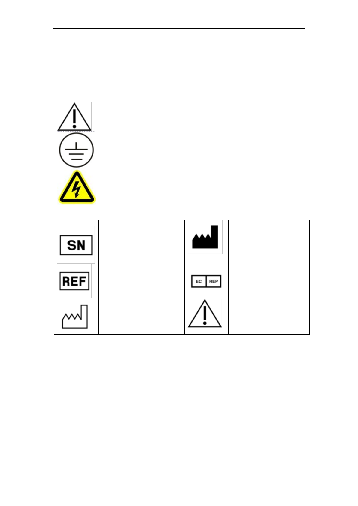
2.1. Sign Explanation..........................................................................................................7
2.2. General Safety Recommendations..............................................................................8
2.3. Safety Parts..................................................................................................................8
2.4. Operation Risk .............................................................................................................8
2.5. Protection Tool.............................................................................................................8
Chapter 3 Description and Specification ....................................................................................9
3.1 Overview.......................................................................................................................9
3.2 Specification................................................................................................................10
3.4 Appearance and Structure ..........................................................................................14
3.5 Safety Requirements...................................................................................................15
3.6 Cable and Pipeline Protection.....................................................................................15
3.7 Control Device.............................................................................................................15
3.8 Cleaning and Disinfection ...........................................................................................15
3.9 Environmental Tests....................................................................................................15
3.10 Packaging Specifications...........................................................................................15
Chapter 4 Installation................................................................................................................16
4.1 Before Installation .......................................................................................................16
4.2 Power Connection.......................................................................................................18
4.3 Fixed Dental Chair ......................................................................................................19
4.4 Exchange Position ......................................................................................................20
4.5 Pipeline Layout............................................................................................................21
4.6 Pipeline and Electron Connection...............................................................................22
4.7 Light Arm and Operation Light Assembly....................................................................22
4.8 Cuspidor Assembly .....................................................................................................22
4.9 Balance Arm Assembly...............................................................................................22
4.10 Handpiece and 3-Way Syringe Assembly.................................................................23
Chapter 5 Operation and Debugging........................................................................................24

Dental Delivery Unit Operation Manual
REV-A
Page 5 of 45
5.1 Power On / Off Button.................................................................................................24
5.2 Emergency Stop Plate ................................................................................................24
5.3 Operation Panel..........................................................................................................24
5.4 Foot Control ................................................................................................................26
5.5 Chair Movement..........................................................................................................27
5.6 Debugging...................................................................................................................27
5.7 Handpieces .................................................................................................................33
5.8 3-way Syringe .............................................................................................................33
5.9 High suction and Low Suction.....................................................................................34
Chapter 6 Sterilization ..............................................................................................................24
6.1 Dental Chair.................................................................................................................35
6.2 Saliva Ejector ..............................................................................................................35
6.3 Handpiece...................................................................................................................35
6.4 Other Metal Instruments..............................................................................................35
Chapter 7 Maintenance ............................................................................................................36
7.1 Daily Maintenance ......................................................................................................36
7.2 Clean Filter..................................................................................................................36
7.3 Common Malfunction and Solution.............................................................................36
Chapter 8 Essential Information ...............................................................................................39
8.1 Basic Information ........................................................................................................39
8.2 Safety Information.......................................................................................................39
Chapter 9 Transportation and Storage .....................................................................................41
Chapter 10 After-sales Service.................................................................................................42
Appendix 1 Electronic and Pipeline Diagram...........................................................................43
Electric Diagram................................................................................................................43
Pipeline Diagram...............................................................................................................45

Dental Delivery Unit Operation Manual
REV-A
Page 6 of 45
Chapter 1 Introduction
1.1. Attention
This Operation manual contains the necessary information to operate the dental unit, this
covers optimal usage, instructions for safe and reliable operation of the unit and information
with regards to regular and correct servicing requirements. Read and understand all
instructions in this manual before using the product.
Keep this manual with the unit at all times. Periodically review the operation procedures for
operation and safety precautions.
1.2. Usage Indications
The chair-mounted dental unit is intended to properly position a patient to perform dental
procedures. A dental operating unit is attached to supply power and serves as a base for other
dental devices, such as a dental handpiece, a dental operating light, an air or water syringe
unit, and oral cavity evacuator, a suction unit, and other dental devices and accessories.
This dental unit can be used by dental clinics, laboratories, hospitals and so on, and should be
operated by doctors and professionals for diagnosing, examining and operating.
1.3. Contraindication
There is not any contraindication of this equipment.

Dental Delivery Unit Operation Manual
REV-A
Page 7 of 45
Chapter 2 Safety
2.1. Sign Explanation
Device Sign Description
“ATTENTION” - Indicates the user to refer to the operation manual or other
instructions when complete information cannot be provided on the label.
“PROTECTIVE EARTH” - Indicates the protective earth (grounding) terminal.
Label Description
Symbol for
"SERIAL NUMBER"
Symbol for
"MANUFACTURER"
Symbol for
"CATALOGUE NUMBER"
Symbol for
"AUTHORISED
REPRESENTATIVE IN
THE EUROPEAN
COMMUNITY"
Symbol for
"DATE OF MANUFACTURE"
Symbol for
"ATTENTION"
Operation Prompt
Note
Indicates that the provided information increases the ease of use or is helpful
when operating the device.
Caution
Indicates that a potential hazard may exist, which through inappropriate
conditions or operation, may cause:
• Minor injury
• Property damage
• Damage to machine
Warning
Indicates that a specific hazard may exist, which through inappropriate
conditions or operation, may cause:
• Severe personal injury
• Substantial property damage
• Substantial damage to machine
NOTE
PLEASE APPLY THE PRECAUTIONS OR RECOMMENDATIONS INDICATED
IN THE OPERATION MANUAL.

Dental Delivery Unit Operation Manual
REV-A
Page 8 of 45
2.2. General Safety Recommendations
The user is responsible for proper operation and maintenance of the unit in accordance with
the instructions listed in this manual.
2.3. Safety Parts
Temperature Protection
Part Name
Function
Temperature Protector
(Heating bottle)
Cut off current when the heating bottle temperature is too high.
Electricity Protection
Part Name
Function
Fuse (Power Impute)
Cut off current when the connected power is too high or
unstable.
Fuse (X-ray Viewer)
Cut off current when the connected power is too high or
unstable.
Control Part
Part Name
Function
Operation Panel
The main control panel of the dental unit
Foot switch
Controls the air and water supply
Foot control
The foot control button controls the movement of the dental chair
PCB Control
Control system for all the process of operation
CAUTION
THE MANUFACTURER CAN NOT BE HELD RESPONSIBLE FOR ANY
ARBITRARY DISASSEMBLY, OR AMENDMENT OFF WITH THE UNIT, BY AN
UNAUTHORIZED PERSON OR AN UNPROFESSIONAL TECHNICIAN.
2.4. Operation Risk
Please pay attention to operation risk during operation.
Squeeze risk
Please control the operating chair carefully when a patient is lying on it to avoid squeezing.
2.5. Protection Tool
Name
Function
Rubber glove
Take to avoid infection
Respirator
Take to avoid infection

Dental Delivery Unit Operation Manual
REV-A
Page 9 of 45
Chapter 3 Description and Specification
3.1 Overview
Dental Unit consists of the following:
This Equipment consists of the electric chair (also called dental chair), dental Unit and the doctor
chair (optional). This machine controlled by gas, electricity. Dental chair rotating by the DC motor.
Dental Unit consists of a tray, gargle water supply equipment, strong / weak saliva suction,
cuspidor, three spray gun, dental lamp, view pieces lamp, foot switch, high speed air turbine
headpiece, endoscope (optional) and light curing machine (optional).
( Figure 1) the structure of dental Unit
1 Position foot control 7 Balance arm
2 Foot control 8 Light adjusting arm
3 Dental chair 9 Light pole

Dental Delivery Unit Operation Manual
REV-A
Page 10 of 45
4 Junction box 10 Operation light
5 Rotating arm 11 Control box
6 Instrument tray 12 Auxiliary control frame
13 Assistant console
3.2 Specification
The main performance and technical parameters (including normal working conditions degree)
3.2.1 Working Condition
Operation temperature: 5~40℃
Relative Humidity: ≤85%
3.2.2 Other Working Condition
Gas Resource: Output 550kPa~800kPa; Gas volume should not be less than 50 L/min.
Water Resource: Output 200kPa~400kPa; Water volume should not be less than 10L/min.
Suction pressure: suction pressure should not less than 27 kPa, the gas flow rate should not
less than 340L/min;
Fixed equipment surface should be smooth; the gradient of the installed machine should be
less than 0.5 °
3.2.3 Fuse Information
Type Size Specification Qty Position
RT1-20 φ5×20 6.3A 1 Power Resource
RT1-20 φ5×20 2A 1 Instrument Tray
RT1-20 φ5×20 5A 2 Dental chair
3.2.4 Electronic Specification
Electronic Security Class: I class
Electronic Defending Class: B class
Power type AC.220V ± 22V, 50Hz ± 1Hz’
Input power 1100VA;

Dental Delivery Unit Operation Manual
REV-A
Page 11 of 45
The equipment has the application part, high speed mobile phone (driven by an external
source), electric / hydraulic dental chair (DC motor drive)
Including the equipment operation modes: continuous operation mode;
No input signal, the output signal section;
Non movable and common type equipment, use of prevent splash foot switch
3.3.5 Dental Chair
Dental chair cushion do not less than 480mm and higher than 780mm,
Dental chair backrest angle swing should higher than 50 °.
Dental chair on the no-load time, should keep stable lifting, no jitter, noise and jamming
phenomenon.
Spherical foot switch can control the dental chair position.
Cover decoration materials and filler materials meet the requirements of 5.1.5
YY/T0058-2004.
Headrest meets the requirement of 5.2.1.1 YY/T0058-2004.
Armrest meets the requirements of 5.2.2 YY/T0058-2004.
Carrying capacity meets the requirements of 5.2.3 YY/T0058-2004.
Explosion pressure meets the requirements of 5.2.4 YY/T0058-2004.
the additional loads which under the emergency measures to meet the requirements of
5.2.7 YY/T0058-2004.
The integrated design to meet the requirements of 5.1.1~5.1.4. YY/T0058-2004.
3.3.6 Instrument Stray
Can be stable at each position, the inclination of less than 3°.
Can be stable operation in the range of more than 1000mm and can be stay at any
position.
The maximum of instrument spray weight is 2KG.
3.3.7 Gargle Water Supply Device
Water supply stable, no splashing phenomenon
3.3.8 Saliva Suction Device
The saliva suction device has strong gear position and weak gear position
Weak saliva suction

Dental Delivery Unit Operation Manual
REV-A
Page 12 of 45
A) When water pressure at 200kPa, vacuum degree greater than 27kPa;
B When water pressure at 200kPa, pumping rate greater than 400ml/min.
Strong Saliva Suction
A) When pressure at 400kPa, vacuum degree greater than 10kPa;
B) When pressure at 400kPa, pumping rate greater than 1000ml/min.
3.3.9 Cuspidor
Made on health, strong and anti corrosive glass material, wouldn’t damaging by cuspidor
cleaning and disinfection.
Cuspidor with filtering net can retain any residue which diameter larger than 2mm.
When the cuspidor pressure on 200kPa, the dirty residue which stay on the cuspidor can
be washed clean.
3.3.10 Three-way Spray Gun
Good sealing performance, flexible to opening and closing, adjustable injection direction.
Ability to spray gas or water when respectively pressed water or gas button, also can
spray fog flow when pressed the two buttons at the same time.
3.3.11 Dental Lamp
Dental lamps to meet general requirements for YY/T of 5.1 1120-2009.
Dental lamp brightness to meet general requirements of YY/T of 5.2.1b1120-2009
Dental lamps lighting on the specified area which to meet the rule of YY/T 1120-2009
5.2.2.1, the maximum light point fall in the zone A and the brightness of Zone Ais greater
than the maximum intensity of 75%.
Dental lamp brightness uniformity to meet the requirements of YY/T 1120-2009 5.2.2.3.
Dental lamp is on the any position which around the dental Unit. Above the 60mm line
parallel to the horizontal line where the intensity is less than 1200LX.
During the normal operation, the reflector glare or reflected light does not fall in the eyes
of the patients.
Dental lamp’s color is to meets the requirements of YY/T 1120-2009 in 5.2.4.
Dental lamp’s color and temperature are to meets the requirements of YY/T 1120-2009 in
5.2.5.
Dental lamp’s Radiation heat is to meets the requirements of YY/T 1120-2009 in 5.2.6.
Dental lamp’s shadow is to meets the requirement of YY/T 1120-2009 in 5.2.7.
Dental lamp’s color rendering index” Ra” should greater than 85.
Dental lamp’s UV radiation brightness should to meets the requirements of YY/T

Dental Delivery Unit Operation Manual
REV-A
Page 13 of 45
1120-2009 in 5.2.9.
The moving parts of dental lamp to meets the requirements of YY/T 1120-2009 in 5.3.1.
Dental lamp operating console to meets the requirements of YY/T 1120-2009 in 5.3.2.
Dental lamp in the operation process, can avoid the wire damage by the rotating.
Dental lamp should not be tilted when fixed in the beam or pillar.
When Dental lamp after the location, there is no obvious migration.
Dental lamp control force to meets the requirements of YY/T 1120-2009
Dental lamp design can protection for the broken bulb, the parts of bulb broken will not
splash out.
Dental lamp’s cleaning and disinfection to meets the requirements of YY/T 1120-2009 in
5.4.
Dental lamp’s performance should to meets the safety requirements of YY1120-2009 in
5.5.
3.3.12 View Box
The color of lamp light is milky white, brightness is greater than 4000Lx.
3.3.13 Pneumatic Foot Switch
The gas conditions to meet the requirements of 3.1.2, took down any hand piece from the shelf,
turn on the pneumatic foot switch, the air pressure should meet the hand piece's working
pressure, and the pressure should stable.
3.3.14 Doctor Chair
Doctor chair is available free to move in any direction for load larger than the 1350N state,
Doctor chair support is more than 180N.
The height adjustment range. of doctor chair is more than 130mm which from the highest
point to the lowest point
Doctor Chair can load of 135kg (after initial settlement), means chair height (collapse or
subsidence) is only lower than 10mm.
Doctor chair use of mat materials, filling materials to meets the standard of 3.3.1.5.
water inlet switch have excellent performance to opening and closing.
this machine have excellent performance and water gas system, the several of valves can
easy to use.
sealing: each system is good at sealing, no water leakage and leakage phenomenon.
3.3.15 Noise
Equipment rotating parts running stable, no abnormal noise, working noise is less than 70dB
(except air compressor).

Dental Delivery Unit Operation Manual
REV-A
Page 14 of 45
3.3.16 Explosion Pressure
Pressure system is safety and reliable, no burst or leak problem under the allowed work
pressure.
3.3.17 Pressure Release
All the parts of machine (may generate pressure in the fire accident) are equipped with
pressure relief device.
3.3.18 Additional loads which under the emergency measures.
The equipment afford additional 40kg load, in the interval 1s, test duration 1min, the equipment
shall not leave the ground, no visible damage after the test.
3.3.19 high speed air turbine hand piece: speed ≥ 260 × 103r/min, with medical device
registration certificate.
3.3.20 pneumatic motor hand piece: speed ≥ 22 × 103r/min: hand piece torque ≥ 2.65 N.M,
with medical device registration certificate.
3.3.21 light curing machine: with medical device registration certificate.
3.3.22 Interface traffic of hand piece is adjustable, adjust the range of 28L/min to 40L/min.
3.3.23 Dental Unit meets the general requirements of dental treatment machine.
YY/T1043-2004 "" in 5.
3.3.24 Dental Unit to meets the requirements of "dental treatment machine" YY/T1043-2004
with failed safe device for 5.3.1.
3.3.25 treatment machine to meet the requirements of "dental treatment machine"
YY/T1043-2004 with voltage limiting for 5.3.6
3.4 Appearance and Structure
3.4.1 Equipment configuration should be regular, smooth surface, no obvious bump, scratches,
and burrs.
3.4.2 Dental chair headrest, backrest, cushion, cushion piece shape should be smooth,
uniform color and no crack.
3.4.3 Switch should be flexible, stable to operation, solid installation and make sure without

Dental Delivery Unit Operation Manual
REV-A
Page 15 of 45
loose.
3.4.4Paint devices to meets the requirements of YY/T91055-1999
3.4.5Electroplating devices to meet requirements of YY0076-92
3.5 safety Requirements
To meets the safety requirements of dental treatment machine standards in Appendix A.
3.6 Cable and Pipeline Protection
All cables and pipes with protection, to prevent damaged by friction or tensile under ordinary
use.
3.7 Control Device
Control devices should put in the safety position.
3.8 Cleaning and Disinfection
Any exposed part of dental patient chair is easy for cleaning and disinfection, will not damage
the chair surface and symbol.
3.9 Environmental Tests
Environmental testing to meets the requirements of climate environment test group II,
mechanical environment test group II GB/T14710-2009. Transportation test to meets the
requirements of GB/T14710-2009 in the third chapter and power supply voltage adaptability
test to meets the requirements of fourth chapter.
3.10 Packaging Specifications
Mainframe (OD); 1500X1100X1200mm gross weight: net weight:
Auxiliary crate (OD); 1350X800X750mm gross weight: net weight:

Dental Delivery Unit Operation Manual
REV-A
Page 16 of 45
Chapter 4 Installation
4.1 Before Installation
Before open the box, please check the box plate and box around, make sure no collision
damage and broken, then, according the "packing list" to infection the parts and accessories, if
you have any questions please contact with the sales unit or query to our company.
Note: the process of opening the outer packing shall be safe and orderly, in order to avoid the
damage of equipment and personnel.
4.1.1 Unpack the Accessories
Open the package and take the product out, remove the plastic bag then to take all the
standard accessories out and check it as following:
Item Name QTY Unit Remark
Operating
Light
box
Operation Light 1 Pc
Ornament Ring 1 Pc
Halogen Lamp 1 Pc
Socket hand wrench 1 Pc Assembly Tool
Operation
Light Arm Box
Light Pole 1 Pc
Light Pole Ornament Ring 1 Pc
Light Arm 1 Pc
Light Arm Ornament Ring 1 Pc
Accessory
box
Strong Suction Aspirator Tube 1 Pc
Weak Suction Aspirator Tube 2 Pc
3-way Spray tube 4 Pc
Connection Port 1/4"-8 and
Nut 2 Pc Backup
Connection Port 1/2"-1/4 2 Pc Backup
Fuse 2A 1 Pc Backup
Fuse Tube 6.3A 1 Pc Backup
Gargle Hydrant with O ring 1 Pc
Cuspidor filter 1 Pc
Cuspidor filter cover 1 Pc
Strong Suction Aspirator filter 1 Pc
filter 1 Pc
Water pipe rollΦ8*6 1 Pc
Gas pipe rollΦ8*6 1 Pc
φ4 Plastic Hoop 5 Pc Backup
φ6 Plastic Hoop 5 Pc Backup

Dental Delivery Unit Operation Manual
REV-A
Page 17 of 45
φ8 Plastic Hoop 5 Pc Backup
Gargle pipe O type
ringΦ6.30*1.8 6 Pc Backup
Cuspidor pipeO type
ringΦ5.0*1.5 6 Pc Backup
Gargle deviceΦ2.5*1.8 10 Pc Backup
Rubber gasket 6 Pc
Paper
document
specification 1 Pc
Quality Certificate 1 Set
qualification 1 Pc
4.1.3 Installation Environment
The device should be set in a place as followed:
( Figure 2): The Installation Position

Dental Delivery Unit Operation Manual
REV-A
Page 18 of 45
Please ensure the place has a separate and stable power source supply.
Please ensure the place has the sewage draining tube to connect.
Please ensure the place has air supply.
Please ensure the palace has water supply.
The temperature of environment:5-40℃.
The humidity of environment: ≤85%
Atmosphere pressure:860Hpa~1060Hpa.
4.2 Power Connection
The dental unit should be connected with a stable and separate power source
Please confirm the connection power is complied with specification of nameplate at the
back of dental unit.
CAUTION
DO NOT BEND THE POWER WIRE TO AVOID DAMAGE OF POWER WIRE
DO NOT PUT ANY HEAVY STUFF ON THE POWER WIRE TO AVOID DAMAGE
OF POWER WIRE
DO NOT USE OTHER POWER WIRE TO AVOID DAMAGE OF DENTAL UNIT
DO NOT TRY TO ADD THE POWER WIRE TO AVOID ACCIDENT AND RISK
WRONG WRONG RIGHT
Set Chair and Junction box
CAUTION
THE GRADIENT SHOULD BE LESS THAN 3°. PLEASE ENSURE THE
GROUND IS HORIZONTAL, OTHERWISE IT WILL EFFECT OPERATION AND
PERFORMANCE, THIS MIGHT EVEN CAUSE ACCIDENTS
Before setting the Junction box the please use a hose to exhaust dirty water or air inside the
tube, for cleaning the impurity and dirt.

Dental Delivery Unit Operation Manual
REV-A
Page 19 of 45
Figure 3 - 13 Rubber Pads
CAUTION
PLEASE MOVE JUNCTION BOX AT THE BOTTOM
WHEN YOU MOVE THE CHAIR, PLEASE HOLD THE BALANCE ARM TO
AVOID ANY HURT
DO NOT LIFT THE BALANCE WHEN YOU MOVE THE DENTAL CHAIR.
4.3 Fixed Dental chair
We suggest you to set the chair with a stationary type. Use 6mm anchoring to fix the dental
chair in suitable place. Please follow the picture A.
Figure 4: the bottom plate fixed position of the machine
Table of contents
Other Woson Dental Equipment manuals
Popular Dental Equipment manuals by other brands

Coltene
Coltene CanalPro CL2 user guide

Renfert
Renfert Twister Translation of the original instructions for use

Rem
Rem M-Vac Series installation guide

Waterpik
Waterpik WaterFlosser quick start guide

EMS
EMS AIR-FLOW handy 3.0 Operation instructions

Amanngirrbach
Amanngirrbach Straumann Argotherm user manual