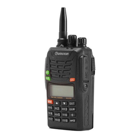
QUANZHOU WOUXUN ELECTRONICS CO., LTD Model: KG-UVD1
Version: KG-UVD1-0905-V1 Page 10 of 43
PIC7
(3)Automatic Power Control Circuit (APC)
APC circuit always monitor the circuit that is through the radio frequency RF amplifier (T142 or T322),and maintain
the stable electric current. The diversification of electronic current that is enlarged by radio frequency power
amplifier can cause the lower voltage of R615, R616, R659 and R660. The voltage is sent to difference amplifier
U612(2/2) U612(1/2), and compares the outputting voltage of IC101(2/2) with the reference voltage from IC405.
The output voltage of U612 (1/2) control the radio frequency RF amplifier, drive amplifier, VG of pre-drive amplifier
to keep the voltage consistent.
The changes of high/low power are realized by changing the reference voltage.
The two terminal amplifiers of this transceiver use the same APC circuit. So they are switched on the
output VG voltage from APC. When U Band transmitting, the VG voltage that sends APC to V Band
resists to ground short circuit. On the contrary, when V Band transmitting, the VG voltage that sends
APC to U Band resists to ground short circuit. See PIC7
(
4)
Coding Signaling
QT/DQT
The DQT/QT data outputs from the CPU 23 base pins. The signal through the low pass CR filter, a partial signal
delivers TCXO CR112. Another part of signal and the tone signaling mix, then inputs separately to U or V Band of
VCO.
ⅤElectrical Power
10 electrical power of 5V is used in this transceiver.
They respectively provide to the microprocessor: 5V,5M
When connecting, 5M always keep outputting. Although 5M is the regular output,it is closed when turn off the
electrical power to prevent the microprocessor from malfunction.
5C-V is the public 5V on V Band,which keeps output on non-save mode.
5C-U is the public 5V on U Band,which keeps output on non-save mode.
5R-U is the receiving 5V on U Band,which keeps output during receiving.
