WPC MRTALP4625DC3 User manual

Rev 7.5/5-22 MRTALP4-DC3: #350581
OPERATING
INSTRUCTIONS 908 W. Main • P.O. Box 368
Laurel, MT USA 59044
800-548-7341 (phone)
406-628-8231 (phone)
406-628-8354 (fax)
www.WPG.com
Record serial number in blank space above (to locate, see serial
label on the product).
LOW-
PROFILE
MANUAL
ROTATOR
/TILTER 600,
DC-VOLTAGE,
WITH INTELLI-GRIP®
TECHNOLOGY & PAD
FRAME T-ARM ASSEMBLIES
(Available with REMOTE CONTROL SYSTEM)
Model number: MRTALP4625DC3
KEEP FOR FUTURE REFERENCE
INTENDED FOR USE BY SKILLED
PROFESSIONALS • READ AND
UNDERSTAND BEFORE OPERATING

MRTALP4-DC3: #35058 Rev 7.5/6-222

Rev 7.5/6-22 MRTALP4-DC3: #350581
SPECIFICATIONS .....................................................................................3
SAFETY...................................................................................................5
OPERATING FEATURES............................................................................6
ASSEMBLY..............................................................................................7
TOASSEMBLE/DISASSEMBLE THE PAD FRAME ...................................................9
Installing/Removing T-Arm Assemblies...............................................................................9
Installing/Removing Vacuum Pads......................................................................................9
Connecting/Disconnecting Vacuum Hoses.......................................................................10
TOADJUST THE PAD FRAME.........................................................................11
Repositioning Vacuum Pads..............................................................................................12
Repositioning T-Arm Cross Members................................................................................12
INTENDED USE .....................................................................................13
LOAD CHARACTERISTICS...............................................................................13
OPERATING ENVIRONMENT..........................................................................13
TYPICAL APPLICATIONS ................................................................................14
DISPOSAL OF THE LIFTER .............................................................................14
OPERATION..........................................................................................15
BEFORE USING THE LIFTER...........................................................................15
Taking Safety Precautions .................................................................................................15
Selecting a Screen Language.............................................................................................15
Performing Inspections and Tests .....................................................................................16
Checking the 12-Volt Battery ............................................................................................16
Preparing to Use the Remote Control System ..................................................................17
TOATTACH THE PADS TO ALOAD ..................................................................18
Positioning the Lifter on the Load.....................................................................................18
Powering up the Lifter ......................................................................................................19
Sealing the Pads on the Load............................................................................................19
Reading the Vacuum Gauges ............................................................................................20
TOLIFT AND MOVE THE LOAD .....................................................................21
About the Tilt Linkage .......................................................................................................21
Interpreting the Lift Light..................................................................................................22
Monitoring Vacuum Indicators .........................................................................................22
Controlling the Lifter and Load .........................................................................................23
TABLE OF CONTENTS

MRTALP4-DC3: #35058 Rev 7.5/6-222
In Case of a Power Failure.................................................................................................23
TOROTATE THE LOAD .................................................................................24
TOTILT THE LOAD ......................................................................................25
TORELEASE THE PADS FROM THE LOAD .........................................................27
AFTER USING THE LIFTER.............................................................................28
Storing the Lifter ...............................................................................................................28
Transporting the Lifter ......................................................................................................29
INSPECTIONS AND TESTS......................................................................30
INSPECTION SCHEDULE ................................................................................30
TESTING ...................................................................................................31
Lifter/Load Compatibility Test...........................................................................................31
Operational Tests ..............................................................................................................32
Vacuum Test......................................................................................................................32
Rated Load Test.................................................................................................................33
Remote Control System Test .............................................................................................33
MAINTENANCE ....................................................................................34
VACUUM PAD MAINTENANCE.......................................................................34
Pad-to-Load Friction Coefficient .......................................................................................34
Pad Inspection ..................................................................................................................34
Pad Cleaning .....................................................................................................................35
TOREPLACE PAD INSERTS IN VPFS625 PADS .................................................36
TOREPLACE SEALING RING IN VPFS10T PADS ...............................................38
12-VOLT BATTERY RECHARGE.......................................................................39
NOTIFICATION BUZZER BATTERY REPLACEMENT ...............................................40
INTELLI-GRIP® DIAGNOSTIC CODES ...............................................................41
REPLACEMENT PARTS...........................................................................45
LIMITED WARRANTY ............................................................................46
TOOBTAIN REPAIRS OR WARRANTY SERVICE...................................................46
TABLE OF CONTENTS

Product
Description
Designed for use with hoisting equipment, MRTALP4-DC3 lifters support loads using vacuum and
manipulate loads using manual 180° rotation and mechanically assisted, manual 90° tilt motions.
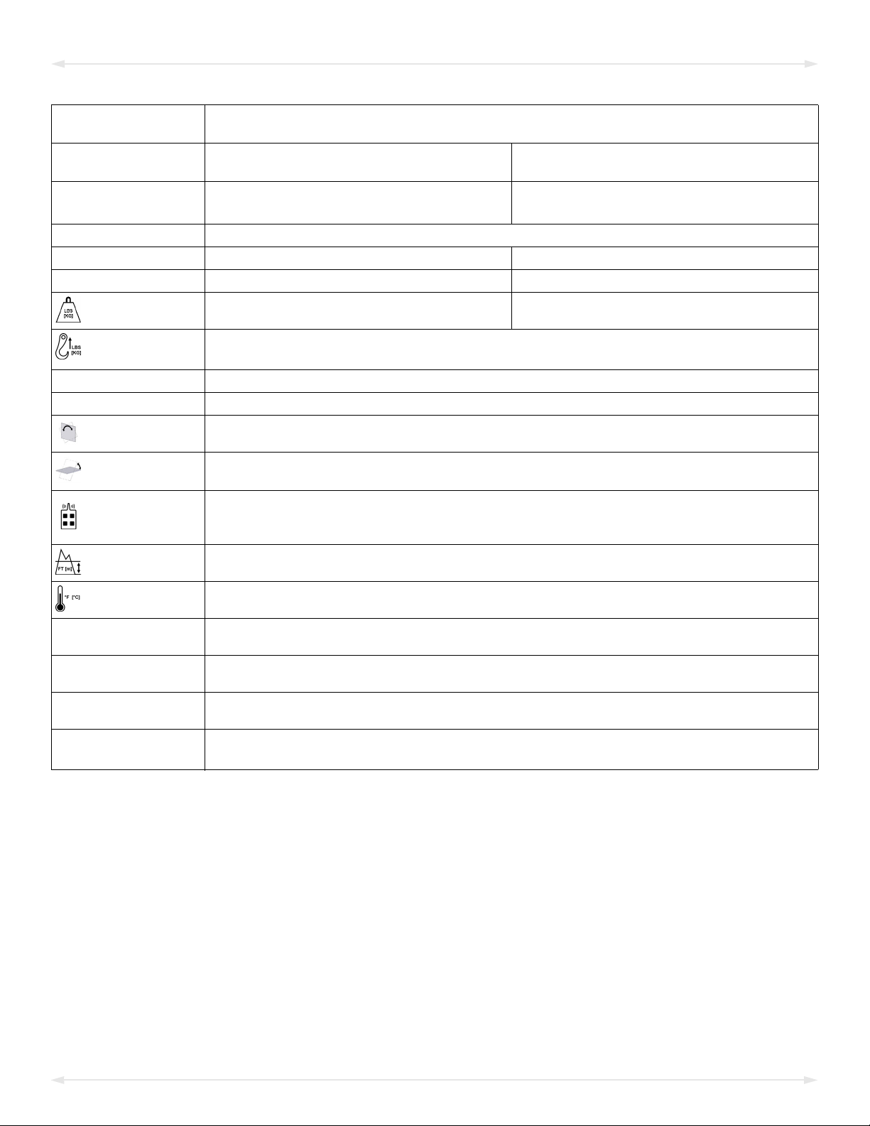
Model
Number MRTALP4625DC3 MRTALP4-DC3
with conversion to VPFS10T vacuum pads
Vacuum
Pads
Four with nominal dimensions
of 6" x 25" [15 cm x 64 cm] (Model VPFS625)1
1...... Standard with replaceable pad inserts for rough or textured surfaces (see “REPLACEMENT PARTS”).
Four 10" [25 cm] nominal diameter
(Model VPFS10T)2
2...... Standard with replaceable sealing rings for rough or textured surfaces (see “REPLACEMENT PARTS”).
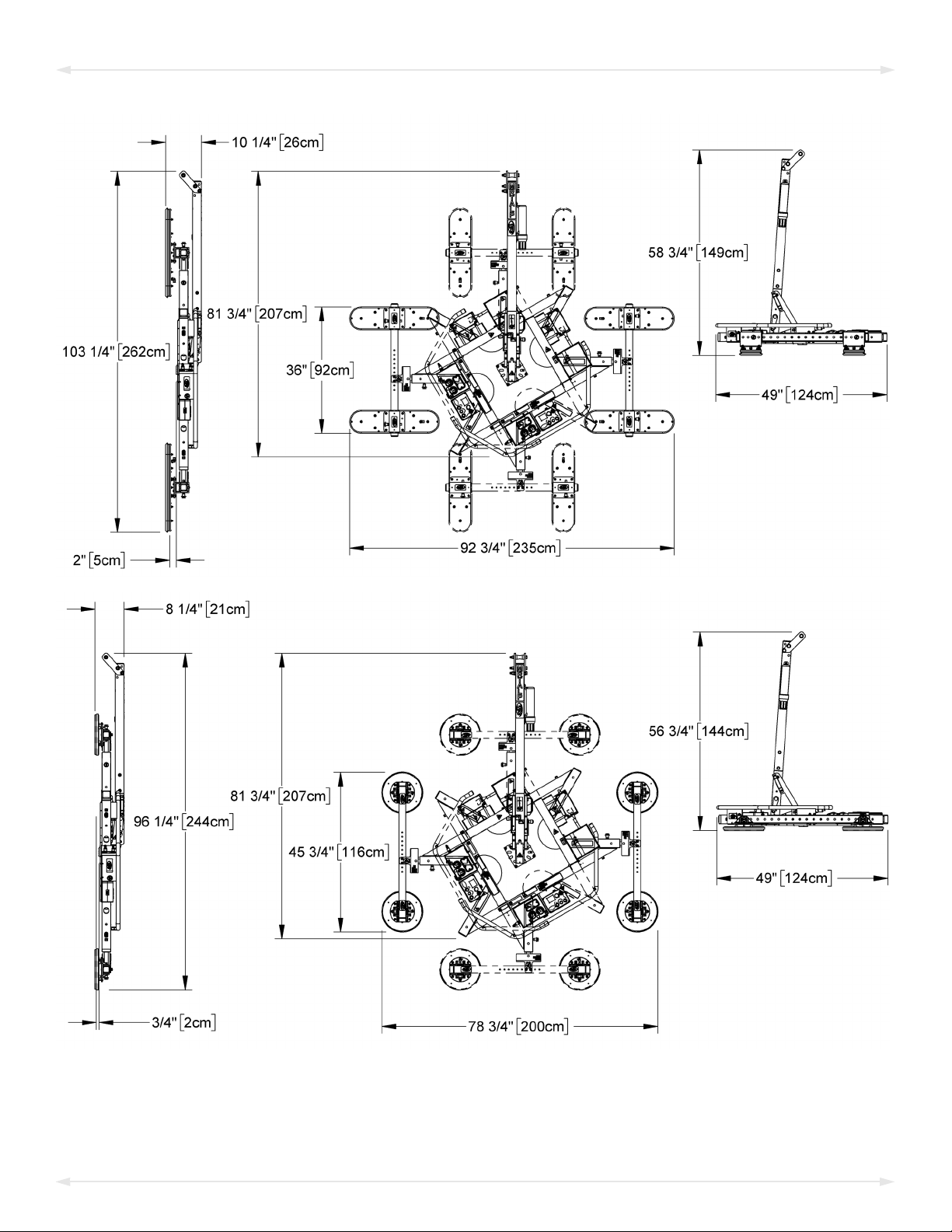
Pad Spread -------------------- (to outer edges) --------------------
Maximum 36" x 92¾" [92 cm x 235 cm] 45¾" x 78¾" [116 cm x 200 cm]
Minimum 20" x 92½" [51 cm x 235 cm] 25¾" x 78¾" [65 cm x 200 cm]
Lifter
Weight 250 lbs [114 kg] 201 lbs [92 kg]
Maximum
Load Capacity3
3...... The Maximum Load Capacity is rated at a vacuum of 16" Hg [-54 kPa] on clean, smooth, nonporous flat surfaces with a friction coefficient of 1. Pad
compound, load rigidity, strength, surface conditions, overhang, angle, center of gravity and temperature can also affect the lifting capacity. A “qualified
person” should evaluate the effective lifting capacity for each use (see definition under “Rated Load Test”).
Per Pad: 150 lbs [68 kg]
Total: 600 lbs [270 kg]
Power System 12 volts DC, 5.5 amps
Battery Capacity 18 amp-hours
Rotation
Capability Manual, 180°, with latching at every 30° of revolution (when required)
Tilt
Capability
Manual, 90°, with four-bar tilt linkage that provides mechanical advantage and automatic latching in
upright position
Product
Options
Available with Remote Control System – FCC, CE, ICC, RSM and ACMA compliant.
Available with conversion to VPFS10T vacuum pads
See separate instructions about other options.
Operating
Elevation Up to 6,000' [1,828 m]
Operating
Temperatures 32° – 104° F [0° – 40° C]
Service
Life 20,000 lifting cycles, when used and maintained as intended4
4...... Vacuum pads, filter elements and other wear-out items are excluded.
Software
Version Intelli-Grip®7.6
ASME Standard
BTH-1 Design Category "B", Service Class "0"
Troubleshooting
Guide5
5...... To view this guide, click the link at right. Additionally, you can search for your lifter's Model Number at www.wpg.com and select the “Troubleshooting” link
on the product page.
TST-021_DC3_REV_2018-023
Rev 7.5/6-22 MRTALP4-DC3: #350583
SPECIFICATIONS

MRTALP4-DC3: #35058 Rev 7.5/6-224
Note: A model MRTALP4-DC3 with standard VPFS625 vacuum pads (top) and optional VPFS10T
vacuum pads (bottom) is shown.
SPECIFICATIONS

Rev 7.5/6-22 MRTALP4-DC3: #350585
SAFETY
Wear personal protective
equipment that is appropriate for
the load material. Follow trade
association guidelines.
Do not remove or obscure safety
labels.
Do not make any modifications to
the lifter (see “LIMITED
WARRANTY”).
Use the lifter only in an approved
“OPERATING ENVIRONMENT”(see
“INTENDED USE”).
Do not use a lifter that is damaged,
malfunctioning, or missing parts.
Do not use a lifter if the sealing
edge of any vacuum pad is cut or
otherwise damaged.
Do not use a lifter to lift cracked or
broken glass.
Do not exceed the Maximum
Load Capacity or lift loads the
lifter is not designed for (see
“INTENDED USE”).
Do not use a lifter if the
Maximum Load Capacity or
any safety label appears to be
missing or obscured.
Make sure the contact surfaces of
the load and vacuum padsare clean
before attaching the lifter (see
“MAINTENANCE”).
Position the vacuum pads correctly
on the load before lifting (see
“OPERATION: Positioning the Lifter
on the Load”).
Do not lift a load if any vacuum
indicator shows inadequate
vacuum.
Keep unauthorized personnel away
from the lifter, to avoid injury in
case of an unintended load release.
Do not touch the vacuum release
controls during a lift.
Do not allow people to ride on the
lifter or the load.
Do not lift a load higher than
necessary or leave suspended loads
unattended.
Do not position a loaded or
unloaded lifter over people.
Before servicing a powered lifter,
place the power control in the
inactive position and, when
possible, disconnect the power source.

MRTALP4-DC3: #35058 Rev 7.5/6-226
Features shown here are underlined on their first appearance in each section following.
1 LIFT POINT 2 INSTRUCTIONS CANISTER 3 LIFT BAR
4 ROTATION RELEASE LEVER 5 PAD FRAME 6 CONTROL HANDLE
7 COTTERLESS HITCH PIN 8 INTELLI-GRIP® CONTROL UNIT 8a LCD SCREEN with BATTERY GAUGE
8b “FUNCTION” BUTTON 8c “ATTACH” BUTTON 8d “RELEASE” BUTTON
8e “POWER” BUTTON 9 Cover for VACUUM PUMP, VACUUM SENSORS 9a AIR FILTERS
9b VACUUM GAUGE 9c VACUUM LIFT LIGHT 9d STROBE LIGHT
10 TILT RELEASE LEVER 11 QUICK CONNECTOR 12 SLIDING/MOVABLE PAD MOUNT
13 PAD FRAME T-ARM ASSEMBLY 14 VACUUM RESERVE TANKS 15 VACUUM PAD
16 BATTERY CHARGER 17 BATTERY Not shown: NOTIFICATION BUZZER
Note: Although some of the following photos do not show this specific lifter, they all illustrate
how this kind of lifter functions.
For information about specific parts, see “REPLACEMENT PARTS” and/or any separate
instructions for Product Options.
OPERATING FEATURES

Rev 7.5/6-22 MRTALP4-DC3: #350587
1) Remove all shipping materials and save them with the shipping container for future use.
2)
2A
If necessary, assemble the lift bar (fig. 2A). Tighten the bolts
(item 2 in fig. 2A) securely.
3) Adjust the lift point to optimize the lifter's hang angle:
3.1) Remove the retaining bolt (item 3 in fig. 2A) and loosen
the pivot bolt (item 4 if fig. 2A).
3.2) Move the lift point to the appropriate position.1
3.3) Reinstall the retaining bolt and tighten both bolts
securely.
Note: Position the lift point to avoid contact with the pad
frame during rotation.
4) Suspend the lifter from appropriate hoisting equipment:
4.1) Select a crane and/or hoist rated for the Maximum Load Capacity plus the
Lifter Weight.
Note: Any lifter use must comply with all statutory or regulatory standards for hoisting
equipment in your region.
4.2)
4A
4B
4C
Pull the tilt release lever
(fig. 4A) to disengage the
tilt latch. Then raise the
lift bar (figs. 4B-C).
1..... Moving the lift point forward (away from operator) helps keep the hang angle vertical while the lifter is loaded; moving the lift point rearward
(towards operator) helps keep the hang angle vertical while the lifter is unloaded.
ASSEMBLY

MRTALP4-DC3: #35058 Rev 7.5/6-228
4.3)
4D 4E 4F
Make sure hook has restraining latch
(see arrow in fig. 4E).
Only use rigging rated for Maximum
Load Capacity plus Lifter Weight.
Attach the hoisting hook to the lift
point (fig. 4D-E).
Note: Use rigging (fig. 4F) as
needed to make sure the hook does
not interfere with the load.
4.4) Use the hoisting equipment to remove the lifter from the shipping container. Avoid
damaging the vacuum pads.
5A
5C
5B
5D
6A
5) Connect the electrical connectors (figs. 5A-B and figs. 5C-D) and install the 9-volt battery
for the notification buzzer as directed in “NOTIFICATION BUZZER BATTERY REPLACEMENT”.
6) Assemble the pad frame for optimal load support (see “TOASSEMBLE/DISASSEMBLE THE PAD
FRAME”). If applicable, remove the pad covers (fig. 6A) and save them for future use.
7) Perform tests as required under “TESTING”.
ASSEMBLY

Rev 7.5/6-22 MRTALP4-DC3: #350589
TOASSEMBLE/DISASSEMBLE THE PAD FRAME
Installing/Removing T-Arm Assemblies
Note: Always position T-arms as shown in“TOADJUST THE PAD FRAME”.
1)
1A 2A
Insert a T-arm
assembly into the
pad frame (fig.
1A).
2) Use a cotterless
hitch pin to
secure the T-arm
(fig. 2A).
3) Install the second T-arm assembly likewise.
To remove the T-arm assemblies, reverse these steps. Store removed components in a clean,
dry location.
Installing/Removing Vacuum Pads
Notes: Use only 2 vacuum pads on each T-arm assembly. Pads must be arranged symmetrically,
to keep the lifter balanced.
1)
1B 2B
Position a sliding/
movable pad mount
on the T-arm
assembly (fig. 1B).
2) Use the cotterless
hitch pin to secure
the pad mount (fig.
2B).
3) Install the other pad mounts likewise.
4) Connect the vacuum pads to the 2 circuits of the dual vacuum system (marked “1” and
“2” in the illustrations under “TOADJUST THE PAD FRAME”).
To remove vacuum pads, reverse these steps. Store removed components in a clean, dry
location.
ASSEMBLY

1A 2A
MRTALP4-DC3: #35058 Rev 7.5/6-2210
Connecting/Disconnecting Vacuum Hoses
Make sure quick
connectors seal
completely and all vacuum
hoses function correctly (see
“Vacuum Test”).
To connect a vacuum hose, push the male and female ends of
the quick connector together until they lock (fig. 1A).
To disconnect a vacuum hose, move the release ring on the
female end until the quick connector separates (fig. 2A).
4A3A
Make sure all hoses are
connected correctly: Green
hose to circuit 1 (fig. 3A) and
red hose to circuit 2 (fig. 4A).
5A
The 2 vacuum gauges are
labeled to indicate the
related circuits (fig. 5A).
Note: The gauge face colors
do not correspond with the
circuit colors.
ASSEMBLY

Rev 7.5/6-22 MRTALP4-DC3: #3505811
TOADJUST THE PAD FRAME
The illustrations above show the range of MRTALP4-DC3 vacuum pad positions available to
accommodate different load dimensions and weight distribution.
Note: These adjustments do not affect the lifter’s Maximum Load Capacity.
Note: VPFS10T vacuum pads, as shown in the bottom illustrations, are available only as a
component of the optional T-Arm Assembly (see #97465HV in “REPLACEMENT PARTS”).
ASSEMBLY

MRTALP4-DC3: #35058 Rev 7.5/6-2212
Repositioning Vacuum Pads
1)
1A
Remove the cotterless hitch pin (fig. 1A) that secures a
sliding/movable pad mount to the pad frame.
2) Position the pad mount as required on the T-arm
assembly.
3) Use the cotterless hitch pin to secure the pad mount.
Repeat these steps to position other pad mounts as needed.
Repositioning T-Arm Cross Members
When more precise pad alignment is needed (eg, on contours of insulated panels), the cross
members of the T-arm assemblies can be repositioned as follows:
1)
1B
Remove the bolts (fig. 1B) connecting a cross member.
2) Move the cross member to the appropriate position.
3) Reinstall the bolts and tighten them securely.
Repeat these steps to reposition the other cross member.
ASSEMBLY

Rev 7.5/6-22 MRTALP4-DC3: #3505813
INTENDED USE
LOAD CHARACTERISTICS
Do NOT lift explosives, radioactive
substances or other hazardous materials.
Make sure the vacuum lifter is intended
to handle each load according to these
requirements:
• The load weight must not exceed the Maximum Load Capacity.
• The load must be a single piece of relatively nonporous material with a flat and
relatively smooth contact surface.1Flexible sealing rings can accommodate some surface
relief, provided contour changes are not too abrupt. To determine whether the load is
too porous or rough, perform the “Lifter/Load Compatibility Test”.
• The load's contact surface must be able to obtain a friction coefficient of 1 with the lifter's
vacuum pads (see “Pad-to-Load Friction Coefficient”). Otherwise, the capacity should be
derated appropriately.
• The load's surface temperature must not exceed the Operating Temperatures.2
• The load's minimum length and width are determined by the current Pad Spread
(see “SPECIFICATIONS”).
• The load's maximum length and width are determined by its allowable overhang.3
• 8" [20 cm] is the allowable thickness at Maximum Load Capacity.4
Note: Standard vacuum pads can stain or deform load surfaces with light colors or soft
coatings. Test such surfaces for damaging effects before using the lifter on them.5
OPERATING ENVIRONMENT
Make sure the vacuum lifter is intended for use in each work environment, given the following
restrictions:
1..... A “single piece” of material includes curtainwall assemblies, unitized glazing systems and similar construction units.
2..... Vacuum pads made from a heat-resistant rubber compound can enable you to lift loads with higher surface temperatures. Contact WPG or an
authorized dealer for more information.
3..... The allowable overhang is the amount of load material that can extend sideways beyond the vacuum pad without breaking or otherwise being
damaged. This depends on the load material, its thickness, and the angle of handling (if any). Since every material has different physical
properties, the allowable overhang must be evaluated separately for each load type. Contact WPG or an authorized dealer for more
information.
4..... However, the allowable thickness increases as load weight decreases. Contact WPG for more information.
5..... Alternative rubber compounds are available for these purposes. Contact WPG or an authorized dealer for more information.

MRTALP4-DC3: #35058 Rev 7.5/6-2214
•
Never use lifter in dangerous
environments.
Metal particles and similar
environmental contaminates
could result in vacuum pump failure.
This lifter is not intended for any environment
that is dangerous to the operator or damaging
to the lifter. Avoid environments containing
explosives, caustic chemicals and other
dangerous substances.
• The work environment is limited by the Operating Elevation and Operating
Temperatures.1, 2
• The lifter is not designed to be watertight.
Moisture can result in
reduced lifting capacity.
Do not use
it in rain or other unsuitable conditions.
TYPICAL APPLICATIONS
•
1A
1B
1C
Fig. 1A — “On center” of
roof panel (pad frame
extensions required)
• Fig. 1B — “On center” of
horizontally oriented wall
panel
• Fig. 1C — “Above center” of
vertically oriented wall
panel
(See “Positioning the Lifter on the
Load”)
DISPOSAL OF THE LIFTER
After the Service Life of the vacuum lifter has ended (see “SPECIFICATIONS”), dispose of it in
compliance with all local codes and applicable regulatory standards.
Note: Special disposal regulations may apply to the battery.
1..... Although lifter use may be possible at higher elevations, lifting capacity is reduced whenever the lifter is unable to attain vacuum in the green
range on the vacuum gauges. Contact WPG for more information.
2..... Special provisions may allow the lifter to operate outside the specified temperature range. Contact WPG for more information.
INTENDED USE

Rev 7.5/6-22 MRTALP4-DC3: #3505815
OPERATION
BEFORE USING THE LIFTER
Determine whether the vacuum lifter is capable of each intended task (see “SPECIFICATIONS”
and “INTENDED USE”). Then complete the following preparations:
Taking Safety Precautions
•
Read all directions and safety
rules before using lifter.
Always wear appropriate
personal protective equipment.
Be trained in all industry and regulatory
standards for lifter operation in your region.
• Follow trade association guidelines about
precautions needed for each load material.
Selecting a Screen Language
When the lifter is powered up for the first time, the Intelli-Grip®
control unit prompts the operator to select a language for the LCD
screen. Use the buttons as follows:
•To scroll down, press the “release” button ( ).
•To scroll up, press the “attach” button ( ).
•To select a language, press the “function” button ( ).1
Note: A similar process is used to navigate all menus.
1..... To change the language again, refer to the “INTELLI-GRIP®OPERATOR MENUS” section of the SERVICE MANUAL.

MRTALP4-DC3: #35058 Rev 7.5/6-2216
Performing Inspections and Tests
• Follow the “INSPECTION SCHEDULE”and “TESTING”.
•
Examine air filters regularly
and service when needed.
Service the 2 air filters whenever a bowl contains
liquid or other contaminates, or an element
appears dirty (see “AIR FILTER MAINTENANCE” in
SERVICE MANUAL).
•
Make sure
notification
buzzer can be
heard over noise
at operator
position.
Make sure the notification buzzer is clearly
audible at the maximum distance between the
operator and the lifter, despite any barriers or
obstacles.1, 2
Checking the 12-Volt Battery
Always check battery
energy before every lift.
While the lifter is powered up, a battery gauge on the LCD
screen displays the current energy level.3, 4
• If battery energy is in the red range, discontinue lifter
use and charge the battery (see “12-VOLT BATTERY
RECHARGE”).
• If battery energy continues to decrease and you try to
attach the lifter to a load, the notification buzzer will
sound continuously and the LCD screen will display “Lockout (low 12V battery)”, along
with a diagnostic code (see “INTELLI-GRIP® DIAGNOSTIC CODES”). In this case, you must
charge the battery in order to continue using the lifter.
1..... Maximum buzzer volume is 95 dBA at 2' [60 cm]. If CE or UKCA Standards apply, consult EN 7731 to make sure the notification buzzer is
compliant.
2..... The “Vacuum Test” provides a convenient opportunity to check this.
3..... If the lifter remains in “Power Save” mode for a long time, the pump will run periodically to test the battery.
4..... If the battery charger is connected to an AC power source, the reading on the battery gauge will not be accurate and “Replace 12V battery?”
may appear on the LCD screen, because the system cannot accurately evaluate the battery.
OPERATION

Rev 7.5/6-22 MRTALP4-DC3: #3505817
Preparing to Use the Remote Control System
1 EMERGENCY DISCONNECT BUTTON
2 TRANSMISSION INDICATOR LIGHT
3 “RELEASE” BUTTON
4 “ATTACH” BUTTON
5 POWER/“FUNCTION” BUTTON
1A
The optional radio transmitter (fig. 1A) and radio
receiver enable you to activate the lifter's “attach”
and “release” functions at distances up to 250' [76 m],
provided you have a clear and direct view of the lifter and
its status indicators.
To operate a lifter remotely, follow these safety rules:
• Visually verify the status of the lifter and load prior
to lifting.
Make sure nearby personnel are aware
of intended remote control actions.
• Monitor the lifter at all times to make sure it is
functioning as intended.1
• Be sure the load is lowered and supported correctly
before releasing it (see following sections).
Note: To prevent any radio transmission, press the
emergency disconnect button.2
1..... The Remote Control System is designed to prevent multiple lifters from responding. Nevertheless, radio-controlled lifters should be tested to
make sure each transmitter controls only one lifter.
2..... To reset the emergency disconnect button, twist the button clockwise and allow it to spring outward to its original position.
OPERATION

MRTALP4-DC3: #35058 Rev 7.5/6-2218
TOATTACH THE PADS TO ALOAD
Make sure that the contact surfaces of the load
and the vacuum pads are clean (see “Pad
Cleaning”).
Positioning the Lifter on the Load
Attach lifter to load as directed below. Failure to follow instructions could result in
load damage or personal injury.
1) Attach the lifter to the load “on center” or “above center”, as required:
•
1A
To rotate and tilt
loads normally,
center the pad
frame on the load
(“on center” —
fig. 1A).1
•
1B
To tilt loads lengthwise from the flat to upright
orientation, center the pad frame from left to right on
the load, and position the vacuum pads toward what
will be the top end when upright (“above center” —
fig. 1B). The load will automatically tilt to the upright
position when lifted.
2) Make sure all vacuum pads will fit on the load and will be
loadedevenly.
Consult the Per-Pad
Load Capacity.
3) Place the vacuum pads in contact with the load surface.
1..... The lifter is designed to handle the maximum load weight when the load’s center of gravity is positioned within 2" [5 cm] of the lifter’s rotation
axis. Off-center loads may rotate or tilt unexpectedly.
OPERATION
This manual suits for next models
1
Table of contents
Other WPC Industrial Equipment manuals
Popular Industrial Equipment manuals by other brands

SPX Cooling Technologies
SPX Cooling Technologies Marley Geareducer 2200 user manual

MIYAWAKI
MIYAWAKI ER110 user manual

OK INDUSTRIAL
OK INDUSTRIAL DTM 510 manual

GCC Technologies
GCC Technologies Laser Pro DFS Installation & operation manual

Dynamics
Dynamics Dings 71010-EC6S instructions

paladin
paladin FFC LAF5412 Operator and parts manual

SUHNER MACHINING
SUHNER MACHINING MAX200 Technical document

SCHUNK
SCHUNK PFH 30 Assembly and operating manual

Lifetime
Lifetime 60309 Assembly instructions

AAF
AAF OptiFlo RC Series Installation, operation and maintenance manual

REED
REED PES1 04290 quick start guide

Habegger
Habegger HIT-TRAC 32E Original user guide