WPT POWER Wp1-03-000 Instruction Manual

Page 1of 10 WIM-PD-003 REV_D
Power Pump Drive (PPD)
Installation & Maintenance
Manual
Unit #’s WP1-03-000, WP1-03-001 & WP1-03-002

Page 2of 10 WIM-PD-003 REV_D
Contents
1.0 Introduction ____________________________________________________________ 3
2.0 General Warnings _______________________________________________________ 4
3.0 Installation_____________________________________________________________ 5
4.0 Maintenance ___________________________________________________________ 6
5.0 Belt Replacement _______________________________________________________ 6
6.0 Exploded View __________________________________________________________ 7

Page 3of 10 WIM-PD-003 REV_D
1.0 Introduction
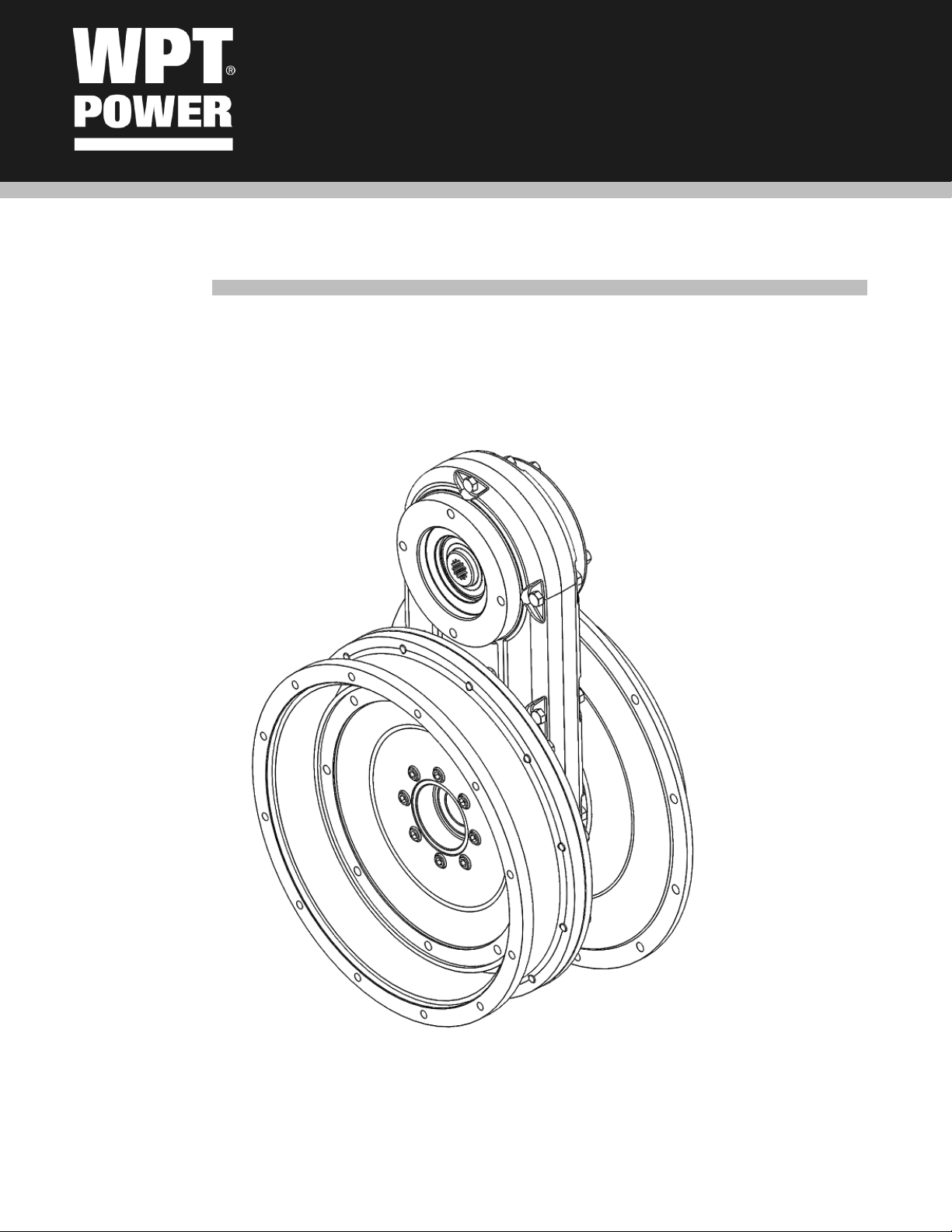
The WPT Power Pump Drive model WPD-03 is an innovative modular pump drive designed to
be mounted on industrial engines with SAE flywheels and housings. The input is a rugged
Rubber Block Drive flywheel coupling. This elastic coupling absorbs radial and angular
misalignments as well as dampens torsional vibrations. The model WPD-03 output is a dual pad
pump drive as well as SAE flywheel and flywheel housing. To allow for easy installation the
pump tower can be mounted in 12 possible positions over 360 degrees. The output flywheel
can accept transmissions, pumps, compressors, and PTO’s.
Throughout the manual there are several HAZARD WARNINGS that must be read and followed to
prevent possible loss of equipment and/or personal injury and/or loss of life. The three warning words
are “DANGER”, “WARNING” and “CAUTION”. They are used to indicate the severity of the hazard and
are preceded by a safety alert symbol.
DANGER
Denotes the most serious injury hazard and is used when serious injury or death WILL result from
misuse or failure to follow the specific instructions sit forth in this manual.
WARNING
Denotes when serious injury or death MAY result from misuse or failure to follow the specific
instructions set forth in this manual.
CAUTION
Denotes when injury, product or equipment damage may result from the misuse or failure to follow
the specific instructions set forth in this manual.

Page 4of 10 WIM-PD-003 REV_D
2.0 General Warnings
Before assembling and operating the product, carefully read all the safety and operating
instructions in this manual.
Always follow all the instructions and make sure that all operators standing by the machinery
are wearing protective equipment necessary for the job type and application being performed.
WARNING
Do not use the machinery if you do not understand these instructions. Please refer to the
manufacturer or customer service for assistance.
Maximum ambient temperature 122 F° [50 C°].
Ambient reading should be taken from 8-12 inches [20-30cm] away from unit and at 2 to 3 locations to
get an average.
WARNING
The product must be protected by a convenient cover guard to avoid personal injury or injury
to others.
Axial and radial ventilation openings should be incorporated in the guard for heat dissipation.
If the product is fitted with fusible plugs, the ventilation openings should not be directed
towards operators or any hot or electrical installation.

Page 5of 10 WIM-PD-003 REV_D
3.0 Installation
CAUTION
Before mounting the pump drive onto the engine, it is important to check that the flywheel is within
SAE tolerances.
3.1 Check that the flywheel is within SAE tolerances (see Figure 1).
3.2 Mount aluminum drive ring of the elastic coupling to the flywheel.
Figure 1: Checking that the flywheel runout is within SAE tolerances.
3.3 Mount the pump drive on the flywheel housing of the engine keeping in mind
to align the teeth of the elastic coupling in the respective teeth of the driving
ring. To align the pump drive housing and flywheel housing, use three threaded
rods with adequate lengths, mounted 120° apart on the flywheel housing. To
perform this operation, lift the assembly by using straps or other approved
means. In cases where the configuration includes a power take-off, support the
assembly adequately to ease alignment.
3.4 Mount the pump(s) on the head(s). Utilize pump manufacturers recommended
grease on both internal and external splines of the adapter.
3.5 Read pump(s) and other installed devices maintenance manual to assure
proper lubrication.

Page 6of 10 WIM-PD-003 REV_D
4.0 Maintenance
There are no specific maintenance items for the WPT Power Pump model WPD-03. No lubrication is
required for this unit.
5.0 Belt Replacement
To replace the belt, follow steps below. See exploded view in section 6.
5.1 Remove pump drive from engine
5.2 Remove rubber block coupling assembly by removing bolts (32) and install into (31), use
them as jack bolts to separate from (25).
5.3 Remove flywheel (3) from output side.
5.4 Remove nuts (34) from output side to remove output flange and spacer (36) & (37).
5.5 Remove nuts (34) from engine input side to remove input flange (14).
5.6 Remove bolts (12) to separate belt housing halves (8).
5.7 Replace belt
5.8 Reassemble pump drive and install unit on engine. See Section 7 for bolt torque
specifications.

Page 7of 10 WIM-PD-003 REV_D
6.0 Exploded View
No.
Qty.
DESCRIPTION
No.
Qty.
DESCRIPTION
1
1
SHAFT
21
2
ELASTIC PIN
2
1
BEARING
22
1
TIMING BELT
3
1
FLANGE
23
1
KEY
4
8
KEY HEAD COIL BOLT
24
1
SPACER
5
1
PULLEY TEETH 48-D.50
25
1
HUB
6
1
BEARING
26
1
RBD FLANGE
7
2
KEY
27
8
ELASTIC WASHER
8
2
HOUSING
28
8
SOCKET HEAD BOLT
9
16
SPECIAL BOLT
29
16
RBD RUBBER BLOCK
10
16
WASHER
30
1
DRIVING RING
11
28
WASHER
31
1
QD-SDS HUB
12
8
HEX HEAD BOLT
32
3
SOCKET HEAD BOLT
13
8
NUT
33
8
SCHNORR WASHER
14
1
FLANGE
34
24
NUT
15
1
SHAFT SAE B
35
1
SNAP RING
16
1
PULLEY TEETH 48 - D.40
36
1
SAE 4 FLANGE
17
2
SNAP RING
37
1
SAE 4 SPACER
18
2
BEARING
38
12
HEX HEAD BOLT
19
2
FLANGE SAE B
39
1
COVER
20
8
HEX HEAD BOLT
40
4
HEX HEAD BOLT

Page 8of 10 WIM-PD-003 REV_D

Page 9of 10 WIM-PD-003 REV_D
Bolt Torque Specifications
The following chart applies to ISO metric screws with coarse pitch grades 8.8, 10.9, and 12.9 with clean
surfaces.
Bolt Size
[mm]
Pitch [mm]
Bolt Torque lbf-ft [Nm]
8.8
10.9
12.9
4
0.7
2
[3.1]
3
[4.3]
4
[5.2]
5
0.8
4
[6]
6
[8.5]
7
[10.1]
6
1
8
[10.4]
11
[14.6]
13
[17.5]
7
1
12
[15.7]
16
[22]
19
[26.4]
8
1.25
18
[24.6]
26
[34.7]
31
[41.6]
10
1.5
37
[50.1]
52
[70.5]
62
[84.6]
12
1.75
63
[84.8]
88
[119]
105
[143]
14
2
100
[135]
140
[190]
168
[228]
16
2
151
[205]
212
[288]
255
[346]
18
2.5
209
[283]
294
[398]
353
[478]
20
2.5
295
[400]
415
[562]
497
[674]
22
2.5
392
[532]
552
[748]
662
[897]
24
3
510
[691]
716
[971]
863
[1170]
27
3
745
[1010]
1047
[1420]
1254
[1700]
30
3.5
1010
[1370]
1423
[1930]
1704
[2310]
This manual suits for next models
2
Table of contents
Other WPT POWER Water Pump manuals
Popular Water Pump manuals by other brands

Agilent Technologies
Agilent Technologies Infinity II 1290 user manual

VONROC
VONROC GP527AC Original instructions

Teral
Teral SP3-e instruction manual

GORMAN-RUPP
GORMAN-RUPP SUPER T8A71S-B/FM Installation, operation and maintenance manual

Pentair
Pentair JUNG PUMPEN K2 plus instruction manual

Esco
Esco LP-12 Installation, operation and maintenance manual

Wilo
Wilo 22 EM Installation and operating instructions

Graco
Graco Premier 970199 Instructions-parts list

Ozito
Ozito PSDW-1000 instruction manual

Grundfos
Grundfos Conlift1 LS Installation and operating instructions

Lincoln
Lincoln B Series Service & operating manual

Graco
Graco Husky 1040 Instructions-parts list