....,,--
---------------
-----------------
---
"-
\
1
OM
Reflector
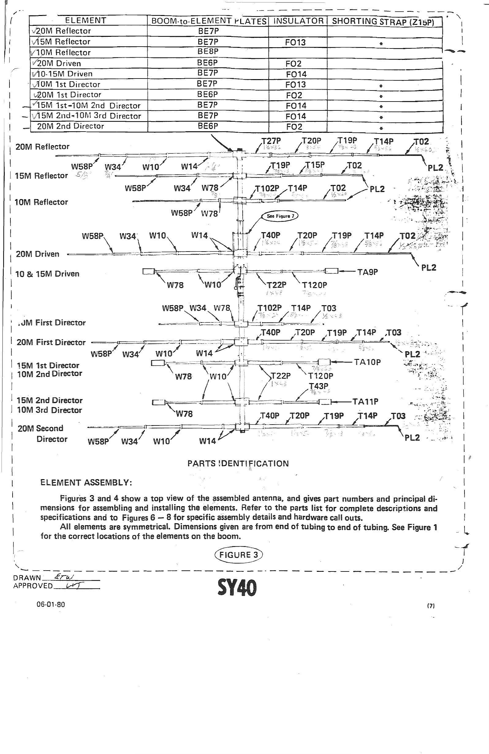
After total assembly it
is
extremely important
to
measure
the
overall lengths
of
aU
elements. Adjust
the
tips
of
aU
full size elements equally on both
~ides
to.obtain
the
correct dimension and inside
the
traps
on
the
trapped elements. . _
Vibrations
in
your
antenna due
to
light winds
will
cause
the
elements
to
sing and herden.
If
the ele-
ments over-harden they will become brittle and crack.
In
order
to
increase
the
life
of
your antenna, we
recommend
the
use
of
5/16"
polypropylene rope threaded through
the
elements
as
described belqw.
Thread
the
rope through
the
7/S"
0.0.
tubing. Epoxy giue
the
rope
to
the inside
of
the tubing which
will have
the
mounting plates attached. After the glue has set, thread each piece
of
the
assembly
onto
the
rope (clamp. tubing. clamp, tubing, etc.). When
the
entire element
is
assembled, dimensioned, and all hard-
ware tightened.
epoxy
the
other
end
of
the rope
to
the
end tube._Cut
the
end
of
the
rope flush with the
tube
and place
the
plastic cap on the end.
Place plastic
~.-
.,'\.$O\I
$$
M!§%$tNitiN"Hi'>S:;'''Hjl~»Uq.*''',;j.,;'"\sssm>''''SWft15~
Epoxy glue
cap onto end Epoxy glue rope
to
inside .rope to tubing
of tubing and cut of.fJI
..
~sh
i\lOTE
..
:The rope is,
to
be installed
the
full
rFiGURE"4'
lengt~
of
all
full sized elements. Rope
is
not
~
:Y
required in
the
trapped elements. !
I
/
--
-- - - -- - - ----- - - - - - ---- - -- - - -
-'
--- - -- - --
--
15M 2nd",10M
3rd
Director
I
I
)I
I
j
r----------
36'-------------·-------------~~
I
-
r74"------1-j50"j44"-r32·:..r-63"--=j
I
-======.
-~=C=~=::::..:ir=:U::=======:U:[J
======~=1X=
::--f~
nun!
,I
20M Reflector 25'-5-112" I
15M Reflector
-.ll
lC---==e~t::::====:::IF=======::::n====~l
-------,fr-
,I
L5O-7/S~
44"-f.--
I
~
-------
24'-1"--1
23'-9-1/2"
~
5_~~_'~:_3_2:_1
5_0_"~
1-.
,:
17'-10"---
r50-5/S"
33'-5"------111-1
21'-1-3/S"
I
~48-3/16"133"-r-44"-t--50"---"""'14-
li I
120M Driven
-=~--'=='C:"=:--
r'
-I
I15'-9-114" ,
10-15M Driven
D=·~--~~=====U~_:..:JJ
c=J
----------:...:....1~-
'.....
I
:
1_
l-99-:1I4'~
-17'-3-~~
,1""1
IF
15',
I
13·-,-~·1/4"1
I
32
-1/2"-l-32~
!
151~
42-1'11/16"
,,.~,
.I
I I Ii
-''''{'7;'~
I
I10M
1st
Director,
5;;/S,JFE"
1111-
50" • r44"----t---3
-2
-"--t-l-i---+-----1-0-,-4-,,--r
7/S"
I
:,20M
1st
Direct()[
~--==
3~'-4~L.
__
=,
_I
7.-fo-S/S":
)15M 1st-10M 2nd
Director
48-5/~.r-.lr--'-~'
1_99.1/4~
IrI
I-
--+16'-4-1/2"
6'-3.3/4"
I
r--'-
1-99.1/4~44-7/81
I
~_:
__
-_-::rr::
.
__
;
~~
Ii'
1~'_9"--jCl
1"
6"
:
20M
2nd
Director
y.
-,""'t
==11.-
11
~
~I
::
0t
Lr
..
!-32,,4-44"-+-60"
•,... f-t In
I.:
I I
31'-2-1/2"
, -
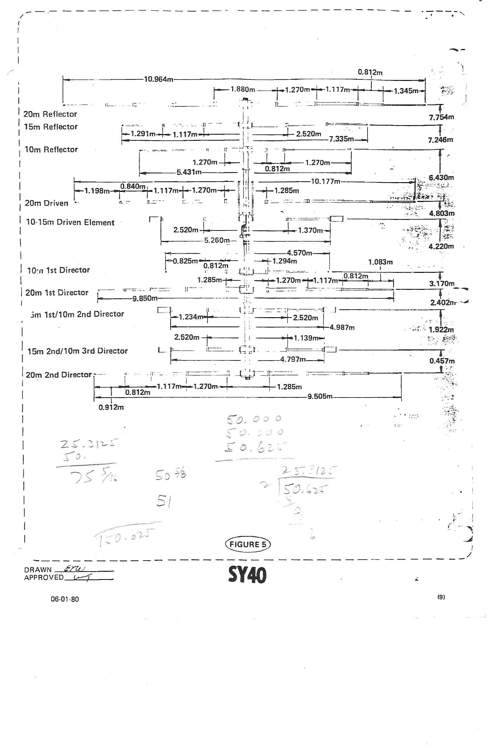
35-15/16" 50-5/S" NOTE: These dimensions are progressive
starting from
the
20m 2nd Director Element.
I
I
I
I
I
I
I
I
I
i
I
I
I
I
I
I
II
I
I
):
L
DRAWN
crtJ
opROVED-1;t-
--1'
·06-01-80
(8)