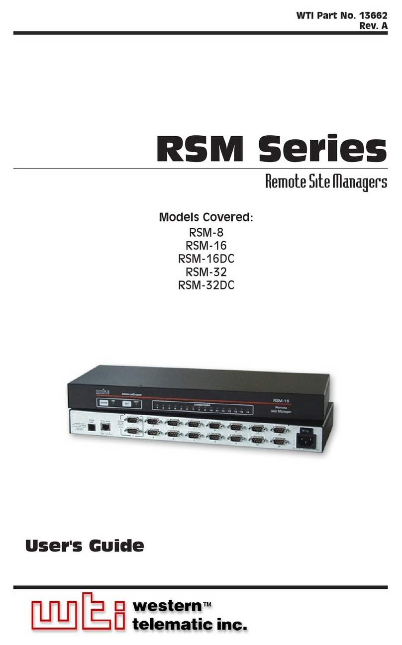
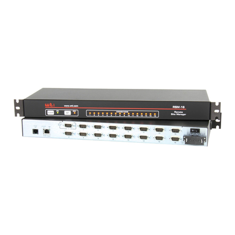
WTI RSM-800 User manual

WTI Part No. 12771
Rev. C
RSM-800
RemoteSite Manager
Preliminary Draft
July 1997
User's Guide

5 Sterling ·Irvine ·California 92618
(949) 586-9950 ·Toll Free: 1-800-854-7226
Fax: (949) 583-9514 ·http://www.wti.com

Table of Contents
1. Introduction ............................................1-1
2. Unit Description.........................................2-1
2.1. Front Panel............................................2-1
2.2. Back Panel ............................................2-2
3. System Overview ........................................3-1
3.1. Communication Parameters..............................3-1
3.2. Apply Power to the RSM-800............................3-2
3.3. Connecting your PC to the RSM-800 .....................3-2
3.4. Communicating with the RSM-800 .......................3-3
4. Hardware Installation ...................................4-1
4.1. Configure Setup Switches ...............................4-1
4.1.1. Default Baud Rate (Sw1, Sw2, Sw3)...............4-2
4.1.2. Default Handshake (Sw4) ........................4-2
4.1.3. Default Response Message Format (Sw5) ..........4-3
4.1.4. Default Command Echo (Sw7)....................4-3
4.2. Initialize the Unit to Default Settings .....................4-4
4.3. Connecting the Network Cable...........................4-4
4.4. Connecting Devices to the RSM-800......................4-5
5. Configuration ...........................................5-1
5.1. Communication During Initial Configuration ..............5-1
5.2. Defining and Reading the Site I.D. .......................5-2
5.3. Port Configuration .....................................5-2
5.3.1. Configuration Conventions .......................5-2
5.3.2. Port Modes.....................................5-3
5.3.2.1. The Net Mode ..........................5-3
5.3.2.2. The Any-to-Any Mode...................5-3
5.3.2.3. The Buffer Mode........................5-3
5.3.2.4. The Modem Mode.......................5-4
5.3.3. Command Availability ...........................5-4
5.3.4. Selecting Parameters for TCP/IP Networks .........5-5
5.3.5. Port Configuration Commands....................5-5
5.4. Implementing IP Security ...............................5-8
5.4.1. IP Security Filter Examples .....................5-10
i

6. Operation ...............................................6-1
6.1. Access to the RSM-800 Command Mode ..................6-1
6.1.1. Access via Local PC.............................6-1
6.1.2. Access via Modem ..............................6-1
6.1.3. Access via TCP/IP Network ......................6-2
6.1.4. Access via Netware 3.x/4.x Network ..............6-3
6.2. Port Connection and Disconnection.......................6-5
6.2.1. Using ASCII Commands to Connect Ports .........6-5
6.2.2. Disconnecting Ports .............................6-7
6.3. Defining Hunt Groups ..................................6-9
6.4. The Buffer Mode......................................6-10
6.5. Pass-through to Network ...............................6-12
7. Saving Configuration Parameters.........................7-1
7.1. Sending Parameters to a File.............................7-1
7.2. Restoring Saved Parameters .............................7-2
8. Command Reference Guide...............................8-1
8.1. Command Conventions .................................8-1
8.2. Command Response ....................................8-2
8.3. Command Summary ....................................8-3
8.4. Command Set..........................................8-4
Appendices
A. Description of System Interface ........................Apx-1
A.1. Ports 2 through 8 (RS-232) ...........................Apx-1
B. Specifications.........................................Apx-2
C. FCC Notice...........................................Apx-3
D. Customer Service .....................................Apx-4
Index
List of Figures
2.1. Instrument Front Panel ......................................2-1
2.2. Instrument Back Panel.......................................2-2
3.1. The RSM-800 Help Screen ...................................3-3
3.2. The Status Screen ...........................................3-4
5.1. Port Configuration Menu (Port 2 Shown).......................5-6
6.1. LIST14 Command Response..................................6-3
A.1. Ports 2 through 8 (RS-232) ................................Apx-1
ii
RSM-800 User's Guide

1. Introduction
The RSM-800 Remote Site Manager provides a cost effective
means for control and management of network hardware without
SNMP in-band restrictions. The RSM-800 allows on-site,
modem, or network communication with any piece of equipment
with an RS-232 command port. Devices can be accessed without
the need to travel to the installation site, even when the network
is down.
Supports Both TCP/IP and Netware 3.x/4.x
The RSM-800 is ideal for both TCP/IP and Netware 3.x/4.x
networks. The unit can be simultaneously configured for both
environments, and will recognize which protocol is being used to
connect. Note however, that only one type of network can
connect at a given time.
Password Protected Network Access
Network access to command functions is protected by a user-
defined password. If unauthorized access is not a concern, the
password feature can also be disabled.
Modem Communication
The RSM-800 can also be controlled via modem. ProComm® (or
another communications program) is used to send commands to
connect ports or display status. When an external modem is
connected, all devices connected to the RSM-800 have access to
the modem. The Modem Port is password protected to restrict
unauthorized access to connected devices.
Versatile Connectivity
The RSM-800 provides a practical solution for applications that
require communication between devices operating at dissimilar
baud rates. Up to 7 different devices can be connected, without
the need to select a common baud rate. Each port can be
individually configured for specific baud rates, parity,
handshaking format, and various other parameters and options.
Easy Set-Up and Operation
Configuration of the RSM-800 is simple. A convenient menuing
system is used to select communications parameters, and enable
or disable options. The RSM-800 can be easily configured to fit
the requirements of almost any data communications application.
1-1

Protected Command Access
The RSM-800 is ideal for situations that require limited access to
important commands. Each port can be individually configured
to allow access to all commands (Administrator), or only allow
access to basic commands (User).
Modular Design
DB9 jacks provide quick, easy connection to computers,
modems, and other LAN hardware. The RSM-800 is compact
and takes only one rack unit (1.75 inches) of vertical rack space
Buffered Ports
The RSM-800 has 256KB of non-volatile, dynamically allocated
buffer memory. This prevents data overflow during
communication between two ports operating at dissimilar baud
rates. The RSM-800 also features a Buffer Mode, which enables
a port to collect data from a connected device and store that data
in an 8 Kbyte revolving buffer.
Configuration Backup
Once you have configured the RSM-800 to fit the requirements
of your application, parameters and options can be sent to an
ASCII text file and saved for future retrieval. If configuration is
accidentally altered or deleted, parameters can be reloaded using
your terminal emulation software.
Typographic Conventions
Throughout this manual, typefaces and characters have been used
to denote the following:
^(e.g. ^E)Indicates a key combination used to invoke
a command. For example, the text “^E”
(Control E) indicates the [Ctrl] key and
the [E] key must be pressed simultaneously.
COURIER FONT Indicates characters typed on the keyboard.
For example, /^E or /P 02.
[Bold Font] Text set in bold face and enclosed in
square brackets, indicates a specific key.
For example, [Enter] or [Esc].
< > Indicates required keyboard entries:
For Example: /P <n>
[ ] Indicates optional keyboard entries.
For Example: /W [n]
1-2
RSM-800 User's Guide

2. Unit Description
2.1. Front Panel
¬CLEAR: Restarts the RSM-800 operating program
without changing user-selected parameter settings or
breaking port connections.
-ON: Lights when AC Power is applied.
®SET: Initializes the RSM-800 to the defaults specified by
the Setup Switches. To initialize, press and hold both the
SET and CLEAR buttons, release only the CLEAR button,
and then release the SET button.
Note:
During initialization, all command-selected
parameters will be cleared, and the default
parameters specified by the Set-Up Switches
will be restored.
¯RDY: Flashes to indicate the unit is operational. Upon
power up, the unit will pause for approximately 45 seconds
before flashing the RDY indicator. During this delay, the
unit will initialize the Network Port.
°ACTIVITY LEDs (1 - 8): Light to indicate that the
corresponding port is receiving data.
2-1
Figure 2.1: Instrument Front Panel

2.2. Back Panel
¬Port 1 (10Base-T Port): An RJ45 Ethernet port for
connection to your Netware 3.x/4.x or TCP/IP network.
Note that, in order to communicate via a TCP/IP network,
the user must first access the Command Mode via Port 2 or
3 and specify an IP Address, Subnet Mask, Gateway
Address, and Network Password as described in
Section 5.3.
-Ports 2 - 8 (RS-232 Ports): For connection to RS-232
devices. Standard DB9 connectors. Please refer to
Appendix A for a description of the RS-232 Port interface.
·Port 2 (Modem Port): Provides all lines required for a
complete interface with a high speed, external modem.
Configured as a DTE port, similar to a standard serial
port on a PC. Port 2 is the only port that can select the
Modem Mode, allowing definition of a password, reset
message, and hang-up message. Port 2 always allows
access to Administrator level commands.
·Port 3 (Setup Port): Used for communication during
initial setup. Provides same communication capabilities
as other RSM-800 RS-232 Ports (except Modem Mode)
and allows local access to Administrator level
commands, even when unit has been reset to default
parameters.
®SETUP Switches: A bank of eight dip switches, used to
set the default baud rate, handshake, message type, port
mode, and duplex mode.
¯Power Switch
°Power Cable Receptacle
2-2
RSM-800 User's Guide
Figure 2.2: Instrument Back Panel

3. System Overview
This section provides a brief overview of the unit's basic
capabilities.
For this overview, a PC or terminal will communicate with the
RSM-800 via RS-232 Port 3. Although the RSM-800 is designed
for applications where the user would normally access the
Command Mode via the Network Port (Port 1), Port 3 provides a
simple means for local access to command functions prior to
actual installation and configuration. After completing this
overview, the RSM-800 should be installed and configured as
described in Sections 4 and 5 of this User’s Guide.
3.1. Communication Parameters
The Setup Switches, located on the Back Panel, select the default
settings for all RSM-800 RS-232 ports. Switch functions are
described on a label on the RSM-800 unit, and in Section 4.1 of
this User’s Guide.
When the RSM-800 is shipped from the factory, the Setup
Switches are configured for 9600 baud, 8 Bits-No Parity, DTR
handshaking, verbose command response, and no echo (all
switches down). For this overview, use the factory selected
Setup Switch configuration. Set your communications program
(e.g. ProComm) to use the following parameters:
·9600 Baud
·8 Bits, No Parity
·DTR Handshaking
·Full Duplex
Using Other Parameters (Optional): If desired, the RSM-800
can also be set to match the parameters used by the
communications program. Refer to Section 4.1 and configure
Setup Switches accordingly. After changing the Set-Up
Switches, initialize the RSM-800 as described in Section 4.2.
Note:
If Setup Switches are changed, new parameters will
not take effect until the unit is initialized.
3-1

3.2. Apply Power to the RSM-800
Connect the power cable to the RSM-800 and plug the cable into
an AC power source. Press the Power Switch to ON. The ON
LED should light, and the RDY LED should begin to flash.
Note:
·Upon power-up, the unit will pause for
approximately 45 seconds in order to initialize the
Network Port. After the 45 second delay has
elapsed, the RDY indicator will begin to flash.
·If all Port Activity LEDs flash upon power-up, this
may indicate a problem with the unit. Please
contact WTI Technical Support as described in
Appendix D.
3.3. Connecting your PC to the RSM-800
Port 3 is generally used for communication during initial set-up
and configuration. This is because Port 3 is the only port
designed for connection to a local PC, that also provides access
to all commands when the unit is initialized to the default state.
Note that after the unit has been installed and configured, the
Network Port (Port 1) and other RSM-800 ports can then be used
to access command functions.
After installation and configuration, the RSM-800 can be
controlled via Network or Modem, or controlled by a local PC
that communicates via cable. For this overview, a local PC
running ProComm (or a similar communications program), will
be cable connected to Port 3.
Note:
Communication via Modem (Optional): If desired,
this overview can also be performed via modem.
Perform the following procedure to connect a PC to Port 3.
1. Attach a standard null modem cable to your PC COM port.
Make certain to connect to the PC COM port used by your
communications program.
2. Connect the other end of the cable to RSM-800 Port 3. For
a description of the port interface, please refer to
Appendix A.
3-2
RSM-800 User's Guide

3.4. Communicating with the RSM-800
Perform the following procedure to enter the Command Mode,
explore the unit's basic features, and check for proper operation.
1. Start your communications program (e.g. ProComm®).
2. Press [Enter] to wake the port and access Command Mode.
a) In order for [Enter] to be recognized as a wake port
command, it must be pressed without any characters
preceding it.
b) If you have already hit other keys, press [Enter] twice.
The “RSM>” prompt should appear.
3. If the “RSM>” command prompt is displayed, you have
successfully accessed the Command Mode. If the
command prompt is not displayed, this may indicate a
communication problem. Check the following:
·Cable Connection: Check the cable connection
between the RSM-800 and the PC. Make certain the
cable connectors are firmly seated.
·Communication Parameters: Make certain the
RSM-800 and ProComm are using the same
communication parameters.
4. Type /H [Enter] to display the Help Screen (Figure 3.1).
3-3
System Overview
/^E Wake-Up Port
/X Sleep - Only Accepts Wake-Up Command
/H Help - Displays Command List
/S Status - Displays Status Screen n Port # or Name
/W [n] Who - Displays Port Parameters N Port #
/C <n> [n] Connect - Local [Remote] | "or"
/D <n> |...| * Disconnect * "all"
/E <n> | * Erase Buffer <> Required Entry
/I Initialize / Test Unit [] Optional Entry
/F Enter Site ID
/J Read Site ID
/P <n> Set Port Parameters
/U Read Port Parameters
/L-[n] Load Port Parameters
/G-00 Reset All Ports
/R Reset Network Port
/D, /E, /I Commands: Add /Y to bypass "Sure? (Y/N)"
Figure 3.1: The RSM-800 Help Screen

5. Type /S [Enter] to display the Status Screen (Figure 3.2).
The Status Screen summarizes conditions at all Ports. The
fields of the Status Screen are explained in Section 8.4.
6. Port Connection: The RSM-800 can perform two
different types of port connections; Resident Connections
and Third Party Connections.
a) Resident Connection: Your resident port (e.g. Port 3)
issues a /C command to connect to a second port.
i. To connect Port 3 to Port 4, type /C 4 [Enter].
While Port 3 is connected to Port 4, the RSM-800
will not recognize commands received via Port 3.
However, the unit will recognize a Resident
Disconnect Sequence issued at Port 3 or Port 4.
ii. Issue the Resident Disconnect Sequence; type
[Enter]+++[Enter].
3-4
RSM-800 User's Guide
SYSTEM STATUS VERSION 1.10 SITE ID:
PORT | NAME | STATUS | BAUD | B/P | HS | MODE | TIMEOUT | BUFF | CTS
------+----------+--------+------+-----+------+--------+---------+------+----
01 | |*Free | ---- | -- | --- | Net | Off | ---- | H
02 | | Free | 9600 | 8N | DTR | Any | Off | ---- | L
03 | | Free | 9600 | 8N | DTR | Any | Off | ---- | L
04 | | Free | 9600 | 8N | DTR | Any | Off | ---- | L
05 | | Free | 9600 | 8N | DTR | Any | Off | ---- | L
06 | | Free | 9600 | 8N | DTR | Any | Off | ---- | L
07 | | Free | 9600 | 8N | DTR | Any | Off | ---- | L
08 | | Free | 9600 | 8N | DTR | Any | Off | ---- | L
Enter /H for Help
Figure 3.2: The Status Screen

b) Third Party Connection: Your resident port (e.g.
Port 3) issues a command to create a connection
between two other ports.
i. To connect Port 4 to Port 5, type /C 4 5 [Enter].
ii. While Ports 4 and 5 are connected, Port 3 will still
recognize RSM-800 commands. Type /S [Enter]
to display the Status Screen. The “STATUS”
column should now list Ports 4 and 5 as connected,
and Port 3 as “Free”.
iii. Issue a Third Party Disconnect command to
disconnect Ports 4 and 5. Type /D 4 [Enter]. The
unit will display the “Sure?” prompt. Type Yand
press [Enter] to disconnect.
iv. Type /S [Enter] to display the Status Screen. The
“STATUS” column should now list Ports 4 and 5 as
“Free”.
7. Define the Site I.D. Message to indicate the name or
location of the unit. The Site I.D. cannot include non-
printable ASCII codes such as NULLS and Line Feeds.
a) Type /F [Enter]. A prompt will appear. Key in the
desired text (up to 32 characters) and press [Enter].
b) To display the Site I.D., type /J [Enter].
c) Note that the Site I.D. will be cleared when the unit is
initialized.
This completes the introductory overview. After you have
determined that the unit is operating properly, install and
configure the RSM-800 as described in Sections 4 and 5.
3-5
System Overview

3-6
RSM-800 User's Guide

4. Hardware Installation
4.1. Configure Setup Switches
When the RSM-800 is shipped from the factory, the Setup
Switches are configured for 9600 baud, 8 Bits-No Parity, DTR
handshaking, verbose command response, and no echo (all
switches down). These settings are compatible with most
applications. If the factory settings are not compatible with your
application, change the defaults as described in this Section.
Setup Switches should be configured to match the
communication parameters used by the device attached to Port 2
or Port 3. This allows access to the RSM-800 if the unit is
initialized to default parameters.
Note:
·Communication parameters (baud rate, parity, and
etc.) can also be individually selected for each
RSM-800 port by accessing Command Mode and
invoking the /P command as described in
Section 5.3.4. The /P command can select different
parameters for each port.
·When the RSM-800 is initialized, parameters will
return to the settings specified by the Set-Up
Switches.
4-1

4.1.1. Default Baud Rate (Sw1, Sw2, Sw3)
Setup Switches one through three select the default baud rate for
Ports 2 through 8. The default baud rate should match the baud
rate your control device will use when communicating with the
RSM-800 via Port 2 or 3. If the control device will communicate
via modem, select a default rate that is compatible with the
modem.
SW
Baud Rate1 2 3
D D D 9600*
U D D 300
D U D 1200
U U D 2400
D D U 4800
U D U 9600
D U U 19.2K
U U U 38.4K
* = Factory Setting
4.1.2. Default Handshake (Sw4)
Setup Switch four selects the default handshake format for
Ports 2 through 8. The default handshake format should be set to
match the device attached to Port 2 or 3. Setup Switch 4 can
select either DTR (hardware) or XON/XOFF handshaking. After
the RSM-800 has been installed, the port configuration command
(/P) can also be used to select DTR handshaking, XON/XOFF,
both DTR and XON/XOFF, or no handshaking.
Switch 4 Handshake
Down DTR *
Up XON/XOFF
* = Factory Setting
4-2
RSM-800 User's Guide

4.1.3. Default Response Message Format (Sw5)
When commands are invoked, the unit can respond with either
Verbose (English text) or Terse (numeric / abbreviated)
messages. Response messages are summarized in Section 8.2.
After installation, the /P command can also set the response
format to “None” (Quiet Mode). When the Quiet Mode is
selected, the unit will not send response messages.
Switch 5 Response Message Type
Down Verbose (English Text) *
Up Terse (abbreviated / numeric)
* = Factory Setting
4.1.4. Default Command Echo (Sw7)
Switch Seven determines the default state for the Command
Echo. When switch seven is placed in the UP position, the
Command Echo will be enabled at all ports when the unit is
initialized to defaults. When the Command Echo is enabled,
characters sent to the RSM-800 will be echoed back to the
control device.
Switch 7 Command Echo
Down Disable*
Up Enable
* = Factory Setting
Note:
·If the Setup Switch configuration is changed, new
parameters will not take effect until the unit is
initialized as described in Section 4.2.
·Setup Switches 6 and 8 are not used.
4-3
Hardware Installation

4.2. Initialize the Unit to Default Settings
If Setup Switches are changed while the RSM-800 is powered on,
the unit must be initialized in order for the new parameters to
take effect. Caution:
After initialization, the unit will revert to the
parameters specified by the Set-Up Switches.
Command-selected parameters will be lost.
Note:
The unit will require approximately 45 seconds to
reset the network port. Do not attempt to connect via
the network port until the RDY indicator begins to
flash, indicating the initialization sequence is
complete.
1. Simultaneously press the SET and CLEAR buttons, located
on the face of the unit.
2. Release the CLEAR button, wait one second, and then
release the SET button.
4.3. Connecting the Network Cable
The Port 1 connector located on the instrument back panel is an
RJ45 Ethernet jack designed for connection to TCP/IP or
Netware 3.x/4.x networks. The RSM-800 can be simultaneously
configured for both TCP/IP and Netware environments, and will
automatically recognize which protocol is being used to connect.
Note however, that only one type of network can connect at a
given time.
Connect your 10Base-T network cable to Port 1 and then
complete the remainder of this installation procedure.
Note
TCP/IP Environment: The RSM-800 must be
correctly configured before the user attempts to
communicate with the unit via a TCP/IP network.
Before attempting to connect to the RSM-800, please
assign the IP Address, Gateway Address, and Subnet
Mask as described in Section 5.3.
4-4
RSM-800 User's Guide

4.4. Connecting Devices to the RSM-800
1. Access the Command Mode.
2. Determine which port will be used for connection to the
new device.
3. Type /S [Enter]. The RSM-800 will display the Status
Screen. Locate the “BUFF” column in the Status Screen to
make certain the port’s buffer is empty.
a) If the Status Screen indicates that the port’s buffer is
not empty, issue the /E command to clear the buffer.
The /E command uses the following format:
/E nn [Enter]
Where nn is the number of the RSM-800 port buffer to
be cleared. For example, to clear the buffer for port
three, type /E 3 and press [Enter].
b) Note that cleared data cannot be recovered.
4. Attach an appropriate DB9 cable to an RS-232 serial port
on the device you intend to connect. Please refer to
Appendix A for a description of the port interface.
a) External Modem: Use a standard serial cable.
b) PCs and other DTE Devices: Use a standard null
modem cable.
5. Connect the other end of the DB9 cable to a vacant
RSM-800 RS-232 port.
6. Select communication parameters for the port as described
in Section 5.3.4.
4-5
Hardware Installation

4-6
RSM-800 User's Guide
Table of contents
Other WTI Network Hardware manuals
Popular Network Hardware manuals by other brands

evertz
evertz 7700 Series manual

National Instruments
National Instruments GPIB-100A user manual

Schaltbau
Schaltbau CP Series Installation and maintenance instructions

Idview Digital
Idview Digital 960H Quick installation guide

IBASE Technology
IBASE Technology ASB200-953 user manual

Balluff
Balluff BNI PG3-508-0C5-Z015 user guide