manuals.online logo
Brands
  1. Home
  2. •
  3. Brands
  4. •
  5. WURM
  6. •
  7. Industrial Equipment
  8. •
  9. WURM FGT003 User manual

WURM FGT003 User manual

FGT003
Product information
FGT003_V4.3.0_PI_2017-12_EN Subject to technical changes Page 1 of 4
Front view
Field module for building technology solutions
Features
Inputs and outputs
- Constant output 0...10V
- PWM output 0…10V
- Analogue input 0…10V / 4…20mA
- 3 x digital inputs 24V=
- 4 x temperature sensor (TRK277, DGF980)
- 3 x relay (2 x NC contact, 1 x NO contact)
Connection of an external display
Emergency program in case of bus errors
No parameters to be set on the device
Bus connection via patch cable and screw terminals (4-pin)
Connection to master module via Wurm CAN field bus (F-bus)
Supplies an external load with max. 3VA
FGT003
Product information
Page 2 of 4 Subject to technical changes FGT003_V4.3.0_PI_2017-12_EN
Writing conventions
Symbol
Meaning
CAUTION!
Avoid the described hazard: otherwise minor or medium physical injury or
damage to property will result.
WARNING!
Avoid the described hazard: otherwise there is danger from electric voltage
that could lead to death or serious physical injury.
For your safety
For safe operation and to avoid personal injury and equipment damage through operating error, always
read these instructions, become familiar with the device, and follow all safety instructions on the product
and in this document, as well as the safety guidelines of Wurm GmbH & Co. KG Elektronische
Systeme. Keep these instructions ready to hand for quick reference and pass them on with the device if
the product is sold.
Wurm GmbH & Co. KG Elektronische Systeme accepts no liability in case of improper use or use for
other than the intended purpose.
Target group
These instructions are intended for service technicians.
Intended use
The FGT003 is a field module for building technology solutions.
WARNING!
Danger to life from electric shock and/or fire!
Switch off the power to the entire plant when installing, wiring or removing! Otherwise a
mains voltage and/or external voltage may still be present even if the control voltage is
switched off! Always remove both power plugs (L and N)!
The wiring of the device should be carried out only by a qualified electrician!
Use only the correct tools for all work!
Check all wiring after connection!
Take note of the maximum loads on all connections!
Never expose the device to moisture, for example due to condensation or cleaning
agents!
Take the device out of operation if it is faulty or damaged and is therefore compromising
safe operation!
Do not open the device!
Do not repair the device yourself! If required, send it in for repair with an exact
description of the fault!
CAUTION!
Electromagnetic interference can cause faults!
Use only shielded data lines and place them far away from power lines!
Software revisions and validity of documentation
Software version
Functional upgrade
Page
V4.3.0
2017-12
Basis of documentation
Any software versions not listed are special solutions for individual projects and are not described in detail in this document. This
document automatically ceases to be valid if a new technical description is issued.
Manufacturer: Wurm GmbH & Co. KG Elektronische Systeme, Morsbachtalstraße 30, D-42857 Remscheid
For further information, see our website at www.wurm.de
FGT003
Product information
FGT003_V4.3.0_PI_2017-12_EN Subject to technical changes Page 3 of 4
Circuit diagram
Fig. 1: FGT003 circuit diagram
Installing
WARNING! Danger to life from electric shock and/or fire!
Switch off the power to the entire plant before installing! Otherwise a mains voltage
and/or external voltage may still be present even if the control voltage is switched off!
Always remove both power plugs (L and N)!
53
106
90
58
Fig. 2: FGT003 dimensions
This device is designed for top-hat rail
installation. The housing is of a standard size
and is also suitable for installation in fuse boxes,
distribution switch boxes or electric boxes of
refrigeration units.
The devices can be positioned immediately next
to one another and without gaps.
Fig. 3: FGT003 top-hat rail installation
Top-hat rail installation
1. Place the module with the upper guide edge
on the top-hat rail.
2. Press it gently downward until it engages
with the fastening safety catch on the top-
hat rail.
FGT003
Product information
Page 4 of 4 Subject to technical changes FGT003_V4.3.0_PI_2017-12_EN
Set address
To correctly register the FGT003 on the bus, you must assign it a unique address using the rotary
switch. This is a requirement for functioning communication with the master module.
Addresses 0-F can be set with the rotary switch. As such, 16 field modules can be connected to the
bus.
Fig. 4: FGT003 rotary switch
Technical data
Power supply 230V~, +10% / -15%, max. 10VA
Display 1 x green LED, operating voltage
2 x green LED, CAN bus data traffic (CAN Tx, CAN Rx)
1 x red LED, flashing in case of fault
Communication 3-wire CAN bus interface, shielded, galvanically isolated,
Screw terminals or RJ45 socket (2x)
Temperature sensor 4 x TRK277 / DGF980
Analogue input 4…20 mA or 0…10 V=, 22 V= supply voltage
External load
Max. 3VA (supply via terminal 47)
Digital inputs 24V=, +20% / -10%, approx. 5mA per input
Output relay 2 x normally closed contact, 230V~, 4(2)A
1 x normally open contact 230V~, 4(2)A
Display / circuit breaker
connection 1 x socket for prefabricated line to display DSP002, DSP100, DSP-
LCD, DSP-Booster or for controlling an ECA970 circuit breaker
Analogue output 1 x 0...10V=, tied to potential, capable of bearing max. 10mA
PWM output 1 x 0...10V=, tied to potential, capable of bearing max. 10mA
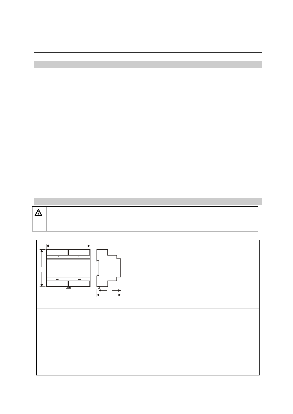
Dimensions (WxHxD) 106 x 92 x 58mm (DIN 43880)
Fastening Top-hat rail TH 35-15 or TH 35-7.5 (DIN EN 60715)
Ambient temperature Operation: 0...+55°C, storage: -25...+70°C
Weight About 275g
CE conformity
−2014/30/EU (EMC Directive)
−2014/35/EU (Low Voltage Directive)
RoHS II
Valid from Version 4.3.0

Other WURM Industrial Equipment manuals

WURM DIN-BL User manual

WURM

WURM DIN-BL User manual

WURM SNT24 User manual

WURM

WURM SNT24 User manual

WURM LUK-XP User manual

WURM

WURM LUK-XP User manual

Popular Industrial Equipment manuals by other brands

ABB +Q957 user manual

ABB

ABB +Q957 user manual

G.B.C BASIC EDGE 50 instruction manual

G.B.C

G.B.C BASIC EDGE 50 instruction manual

Tronair Batpak 11-6602-1000 Operation & service manual

Tronair

Tronair Batpak 11-6602-1000 Operation & service manual

Pilz PNOZ mi2p Operation manual

Pilz

Pilz PNOZ mi2p Operation manual

Clemco Zero BNP 6012 manual

Clemco

Clemco Zero BNP 6012 manual

Erskine Attachments V-Plow Operator's manual

Erskine Attachments

Erskine Attachments V-Plow Operator's manual

ABB HT610965 Operation manual

ABB

ABB HT610965 Operation manual

Morra MH 540 user manual

Morra

Morra MH 540 user manual

Eaton S090ST manual

Eaton

Eaton S090ST manual

GRIGGIO G 240 P4 instructions

GRIGGIO

GRIGGIO G 240 P4 instructions

Nexen AIR CHAMP HT45 user manual

Nexen

Nexen AIR CHAMP HT45 user manual

WTE V5 installation manual

WTE

WTE V5 installation manual

ABB HT845232 Operation manual

ABB

ABB HT845232 Operation manual

SMC Networks CJP Series Operation manual

SMC Networks

SMC Networks CJP Series Operation manual

JohnDow Industries JDI-AFT58 Operator's manual

JohnDow Industries

JohnDow Industries JDI-AFT58 Operator's manual

IMB MB9016A instruction manual

IMB

IMB MB9016A instruction manual

Clarke CUMB1 Assembly & operating instructions

Clarke

Clarke CUMB1 Assembly & operating instructions

amiad Arkal Spin Klin 2 user guide

amiad

amiad Arkal Spin Klin 2 user guide

manuals.online logo
manuals.online logoBrands
  • About & Mission
  • Contact us
  • Privacy Policy
  • Terms and Conditions

Copyright 2025 Manuals.Online. All Rights Reserved.