WIRELESS CONNECTIVITY & SENSORS
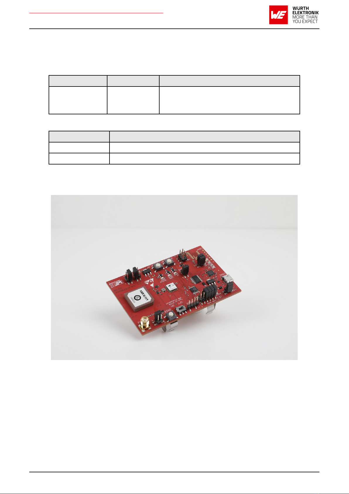
Evaluation board for radio module Erinome-II
Contents
1 Supported radio modules 6
2 Functional description 8
3 Development board 9
3.1 Blockdiagram..................................... 9
3.2 Jumpers........................................ 10
3.3 Connectors ...................................... 13
3.3.1 CON1 .................................... 14
3.3.2 CON2 .................................... 14
3.3.3 CON3 .................................... 14
3.3.4 CON4 (only for 2614029237011) . . . . . . . . . . . . . . . . . . . . . 15
3.4 SwitchesandButtons ................................ 16
3.4.1 RESETGNSSbutton............................ 16
3.4.2 ON/OFFSwitch............................... 16
3.4.3 RESET_RF button (only for 2614029237011) . . . . . . . . . . . . . . 18
3.4.4 WAKE-UP_RF button (only for 2614029237011) . . . . . . . . . . . . . 18
3.4.5 Powersupply ................................ 19
3.4.5.1 Bus powered, power supply through USB . . . . . . . . . . . . . . 19
3.4.5.2 Battery powered (only for 2614029237011) . . . . . . . . . . . . . 19
3.4.6 JP1 - Current Measurement . . . . . . . . . . . . . . . . . . . . . . . . 19
3.4.7 JP2 - UART Communication Interface Selection . . . . . . . . . . . . . 19
3.4.8 JP3 - Communication Interface . . . . . . . . . . . . . . . . . . . . . . 19
3.4.9 JP4 - Antenna Selection . . . . . . . . . . . . . . . . . . . . . . . . . . 19
3.4.10 JP5 - Active Antenna Bias . . . . . . . . . . . . . . . . . . . . . . . . . 20
3.4.11 JP6 - CTS/RTS Pull Resistors . . . . . . . . . . . . . . . . . . . . . . . 20
3.4.12 JP7 (only for 2614029237011) . . . . . . . . . . . . . . . . . . . . . . . 20
3.4.13 JP8 (only for 2614029237011) . . . . . . . . . . . . . . . . . . . . . . . 20
3.4.14UART/USB................................. 20
3.4.15 LED - Erinome-II GNSS module . . . . . . . . . . . . . . . . . . . . . . 20
3.4.15.1 STATUS GNSS LED . . . . . . . . . . . . . . . . . . . . . . . . . . 20
3.4.15.2 1PPSGNSSLED............................ 21
3.4.15.3 TXGNSSLED ............................. 21
3.4.16 LED - Thyone-I radio module (only for 2614029237011) . . . . . . . . 21
3.4.16.1 BUSY_RF and RF_ST1 LED . . . . . . . . . . . . . . . . . . . . . 21
3.4.17 Proprietary RF Block . . . . . . . . . . . . . . . . . . . . . . . . . . . . 21
3.5 Schematic....................................... 22
3.6 Layout......................................... 25
4 Putting into operation 27
4.1 Putting into operation - UART . . . . . . . . . . . . . . . . . . . . . . . . . . . . 27
4.1.1 Putting into operation - UART with Thyone-I proprietary RF module
(only for 2614029237011) . . . . . . . . . . . . . . . . . . . . . . . . . 29
4.2 Putting into operation - I2C.............................. 32
4.2.1 Hardware Setup - Erinome-II . . . . . . . . . . . . . . . . . . . . . . . . 32
4.2.2 Evaluation Board Modification - Erinome-II . . . . . . . . . . . . . . . . 33
4
Version 1.7, May 2023 www.we-online.com/wcs