Wurth Elektronik PROTEUS-III User manual

MINI EVALUATION BOARD USER MANUAL
FOR RADIO MODULES
EV order code Module order code Product Name
2611069024001 2611011024000 Proteus-III
2611119024011 2611011024010 Proteus-III-SPI
2611079021001 2611011021000 Thyone-I
VERSION 1.2
FEBRUARY 25, 2021

***************
MUST READ
Check for firmware updates
Before using the product make sure you use the most recent firmware version, data sheet
and user manual. This is especially important for Wireless Connectivity products that were
not purchased directly from Würth Elektronik eiSos. A firmware update on these respective
products may be required.
We strongly recommend to include in the customer system design, the possibility for a
firmware update of the product.

Revision history
Manual
version
HW
version Notes Date
1.0 1.0 • Initial version October 2020
1.1 1.0
• Order number is updated in the schematic
3.7
.
• Bill of materials is added in chapter
3.9
.
• LFXO crystal part number is updated in chapter
3.6.5
.
• Input capacitance variables CXC 1and CXC2are
changed to CXL1and CXL2respectively
3.6.5
.
January 2021
1.2 1.0
• Added information on Proteus-III-SPI radio
module
• Chapter
LFXO crystal
is updated.
February 2021
Mini evaluation board user manual version 1.2 © February 2021
www.we-online.com/wireless-connectivity 1

Abbreviations and abstract
AbbreviationName Description
EV Evaluation
ESD Electro Static Discharge
FTDI Future Technology
Devices International
GND Ground
HIGH High signal level
JTAG Joint Test Action Group
LED Light Emitting Diode
LFCLK Low frequency clock
LFXO Low frequency crystal
oscillator
LOW Low signal level
NFC Near Field Communication
OTA Over the air
PC Personal Computer
PCB Printed Circuit Board
RF Radio frequency Describes everything relating to the wireless
transmission.
SMA SubMiniature version A
SPI Serial Peripheral Interface
SWD Serial Wire Debug
THT Through-hole technology
UART Universal Asynchronous
Receiver Transmitter
Universal Asynchronous Receiver Transmitter allows
communicating with the module of a specific
interface.
USB Universal Serial Bus
VDD Voltage Drain Drain Supply voltage
Mini evaluation board user manual version 1.2 © February 2021
www.we-online.com/wireless-connectivity 2

Contents
1 Supported radio modules 5
2 Functional description 7
2.1 Taking into operation - PC (Proteus-III/Thyone-I only) . . . . . . . . . . . . . 7
2.2 Taking into operation - Host controller . . . . . . . . . . . . . . . . . . . . . 8
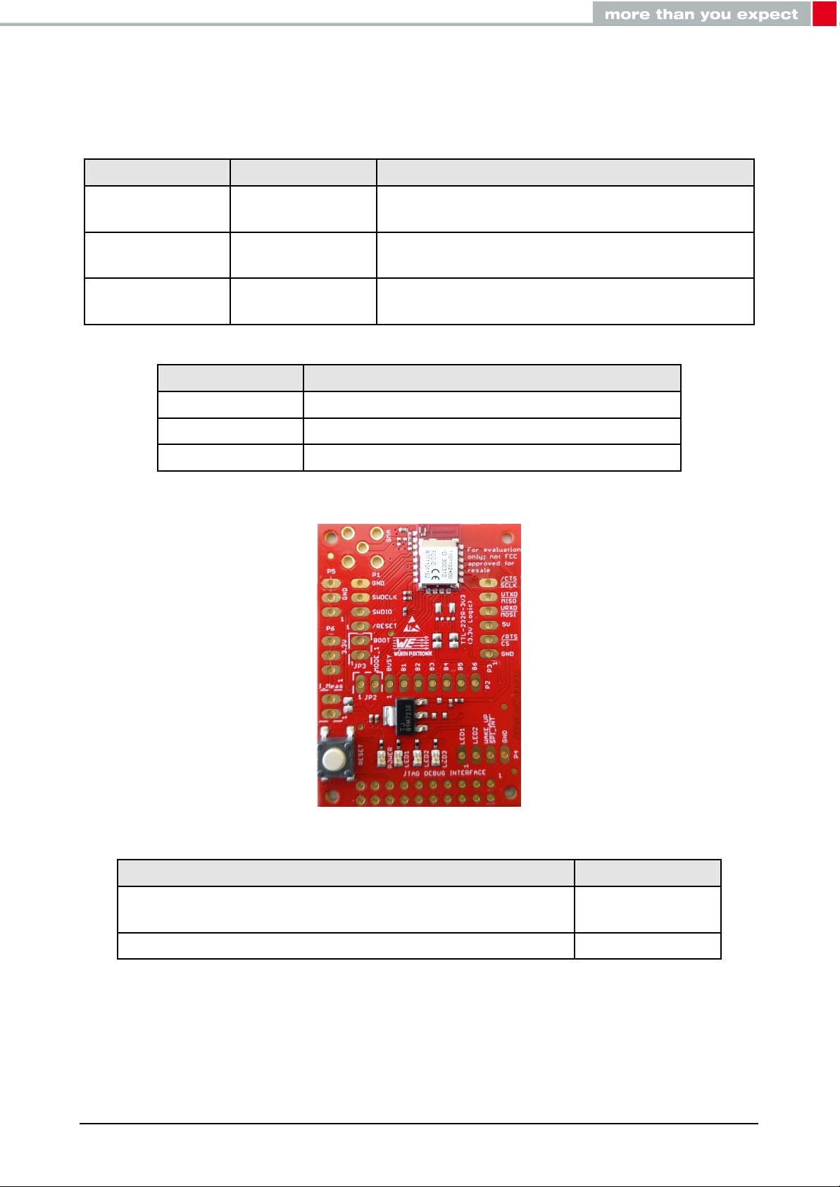
3 Development board 9
3.1 Blockdiagram................................... 9
3.2 Additionalassembly ............................... 10
3.3 Connectorsandports .............................. 12
3.3.1 P1, P2, P4: Module access pins . . . . . . . . . . . . . . . . . . . . 13
3.3.2 P3: TTL-232R-3V3 FTDI cable connector . . . . . . . . . . . . . . 14
3.3.3 P5, P6: Alternative power supply connection . . . . . . . . . . . . . 14
3.3.4 JTAG Debugging Interface . . . . . . . . . . . . . . . . . . . . . . . 14
3.3.5 SMA ................................... 15
3.4 Jumpers...................................... 16
3.4.1 I_Meas: Current measurement . . . . . . . . . . . . . . . . . . . . 17
3.4.2 JP2: Operation mode . . . . . . . . . . . . . . . . . . . . . . . . . . 18
3.4.3 JP3:Bootmode............................. 18
3.5 Resetbutton ................................... 19
3.6 Functionblocks.................................. 20
3.6.1 Powersupply .............................. 20
3.6.1.1 Connector P3, power supply through TTL-232R-3V3 . . . . . . 20
3.6.1.2 Connector P3, power supply through external source . . . . . . 20
3.6.1.3 Connectors P5 and P6, power supply through external source . 20
3.6.2 UART/USB............................... 21
3.6.3 UARTdirect ............................... 21
3.6.4 SPIdirect ................................ 21
3.6.5 LFXOcrystal .............................. 21
3.6.5.1 LFXO Design guidelines . . . . . . . . . . . . . . . . . . . . . . 23
3.6.6 Programming interface . . . . . . . . . . . . . . . . . . . . . . . . . 23
3.7 Schematic..................................... 24
3.8 Layout....................................... 25
3.9 Billofmaterials.................................. 27
4 Regulatory compliance information 28
4.1 EuropeanConformity............................... 28
4.2 FCC ........................................ 28
4.3 Exemptionclause................................. 28
5 Important notes 29
5.1 General customer responsibility . . . . . . . . . . . . . . . . . . . . . . . . . 29
5.2 Customer responsibility related to specific, in particular safety-relevant ap-
plications ..................................... 29
5.3 Best care and attention . . . . . . . . . . . . . . . . . . . . . . . . . . . . . 29
5.4 Customer support for product specifications . . . . . . . . . . . . . . . . . . 29
5.5 Productimprovements.............................. 30
5.6 Productlifecycle ................................. 30
5.7 Propertyrights .................................. 30
Mini evaluation board user manual version 1.2 © February 2021
www.we-online.com/wireless-connectivity 3

5.8 General terms and conditions . . . . . . . . . . . . . . . . . . . . . . . . . . 30
6 Legal notice 31
6.1 Exclusionofliability................................ 31
6.2 Suitability in customer applications . . . . . . . . . . . . . . . . . . . . . . . 31
6.3 Trademarks .................................... 31
6.4 Usagerestriction ................................. 31
7 License terms 33
7.1 Limitedlicense .................................. 33
7.2 Usageandobligations .............................. 33
7.3 Ownership..................................... 34
7.4 Firmwareupdate(s)................................ 34
7.5 Disclaimerofwarranty .............................. 34
7.6 Limitationofliability................................ 34
7.7 Applicable law and jurisdiction . . . . . . . . . . . . . . . . . . . . . . . . . . 35
7.8 Severabilityclause ................................ 35
7.9 Miscellaneous................................... 35
Mini evaluation board user manual version 1.2 © February 2021
www.we-online.com/wireless-connectivity 4

1 Supported radio modules
The evaluation board described in this manual can be used to evaluate the following prod-
ucts:
Order code Product Name Description
2611011024000 Proteus-III Bluetooth®LE 5.1 radio module with smart
antenna configuration
2611011024000 Proteus-III-SPI Variant of the Proteus-III radio module providing
a SPI instead of an UART for host connection
2611011021000 Thyone-I 2.4GHz proprietary radio module with smart
antenna configuration
Order code Product Name
2611069024001 Mini EV Board Proteus-III
2611119024011 Mini EV Board Proteus-III-SPI
2611079021001 Mini EV Board Thyone-I
Table 1: Compatibility
Figure 1: Product image
Content 2611069024001 Quantity
Mini Evaluation board with Proteus-III On-board PCB
Antenna connection 1
Packaging: ESD safe cover 1
Table 2: Content Mini EV Board Proteus-III
Mini evaluation board user manual version 1.2 © February 2021
www.we-online.com/wireless-connectivity 5

Content 2611119024011 Quantity
Mini Evaluation board with Proteus-III-SPI On-board PCB
Antenna connection 1
Packaging: ESD safe cover 1
Table 3: Content Mini EV Board Proteus-III-SPI
Content 2611079021001 Quantity
Mini Evaluation board with Thyone-I On-board PCB
Antenna connection 1
Packaging: ESD safe cover 1
Table 4: Content Mini EV Board Thyone-I
Mini evaluation board user manual version 1.2 © February 2021
www.we-online.com/wireless-connectivity 6

2 Functional description
The mini evaluation board is an intuivitive, application oriented and cost effective version
of the evaluation kit. It offers the user the possibility to develop hard- and software for the
corresponding radio module.
By default, the mini evaluation board is not assembled with connectors and pinheaders. The
necessary components shall be assembled by the user based on the need and application.
The mini evaluation board is intended for experienced developers, as additional accessories
and basic soldering skills are necessary to take the board into operation.
Accessories required:
• Additional assembly components listed in the table
5
.
Connector kit article number: 699100.
• Soldering equipment
• (optional) TTL-232R-3V3 FTDI cable in case of Proteus-III or Thyone-I
For the connection to a micro controller or PC the evaluation board is equipped with place-
holders for standard 2.54mm headers which is connected to the pins of the radio module.
Pin headers can be soldered to the placeholders to access the module pins. Jumpers allow
to set the module into defined modes.
In case of Proteus-III and Thyone-I, the mini evaluation board can be connected to an USB
port of a PC using TTL-232R-3V3 FTDI cable.
2.1 Taking into operation - PC (Proteus-III/Thyone-I only)
To take the mini evaluation board into operation using a PC, additional assembly as de-
scribed in the chapter
3.2
is necessary.
The corresponding FTDI driver package (www.ftdichip.com/Drivers/VCP.htm) has to be in-
stalled on the PC.
The installation guidelines shall be followed:
(https://www.ftdichip.com/Support/Documents/InstallGuides.htm)
The TTL-232R-3V3 FTDI cable shall be connected to the connector P3 of the evaluation
board. It is important that the VDD is stable and able to reliably supply the module’s static
and peak current consumption as specified by the module manual.
Incorrect orientation of TTL-232R-3V3 FTDI cable will damage the RF module.
The next step is to connect the evaluation board to the PC using the TTL-232R-3V3 FT-
DI cable. In that way a COM port can be detected and installed on the PC. In the device
Mini evaluation board user manual version 1.2 © February 2021
www.we-online.com/wireless-connectivity 7

manager the COM port name of the TTL-232R-3V3 FTDI cable can be found. A COM port
shall appear for example: "COM12" in Windows systems or "/dev/ttyUSB0" in Linux systems.
The WE-SmartCommander or any other serial terminal program (like hterm for Windows)
has to be run and the corresponding COM port has to be opened using the default settings
of the mounted radio module. After the module is powered through the TTL-232R-3V3 FTDI
cable or an alternative power supply, the reset button should be pressed to ensure a clean
start-up of the module.
The detailed module specific quick start instructions can be found in the corresponding user
manual.
2.2 Taking into operation - Host controller
To take the mini evaluation board into operation using a host controller, additional assembly
as described in the chapter
3.2
is necessary.
An external power supply shall be connected to the evaluation board. The power supply op-
tion 3 or 4 from the table
17
shall be used. It is important that the VDD is stable and able to
reliably supply the module’s static and peak current consumption as specified by the module
manual.
The next step is to connect the communication lines of the module to the host controller. The
headers P1, P2 and P3 can be used to connect the module pins and host.
The detailed module specific quick start instructions can be found in the corresponding user
manual.
Feel free to check our youtube channel for video tutorials, hands-ons and webinars relating
to our products:
www.youtube.com/user/WuerthElektronik/videos
Mini evaluation board user manual version 1.2 © February 2021
www.we-online.com/wireless-connectivity 8

3 Development board
3.1 Block diagram
5Vto 3.3V
Voltage
regulator Radio module
2.54mm
pin header
P3 (1X6)
Reset
Button
2.54mm pin headers
(Access to module pins)
50Ω port to
λ/4 antenna
Mini evaluation
board
RF Filter &
50Ω matching Internal
Antenna
LEDs
Current
Measurement /
Solderbridge
2.54mm pin
header
Connector
(VDD, GND)
SMAConnector
THT
Alternate
power supply
(3.3V)
UART or SPI
(3.3V logic)
3.3V
5V
Figure 2: Block diagram
Mini evaluation board user manual version 1.2 © February 2021
www.we-online.com/wireless-connectivity 9

The table
5
lists the additional assembly components for the evaluation board. All the com-
ponents listed in the table
5
are THT components.
Placeholder Function Pins WE Article Number
I_Meas Current measurement 1X2 61300211121
JP2 Boot mode set 1X2 61300211121
JP3 Operation mode set 1X2 61300211121
JTAG JTAG Debug interface 2X10 61302021121
P1 Access to module pins 1X6 61300611121
P2 Access to module pins 1X7 61300711121
P3 TTL-232R-3V3 FTDI cable
connection / Access to module pins 1X6 61300411121
P4 Access to module pins 1X4 61300411121
P5 Ground connection 1X3 61300311121
P6 3.3V Connection 1X3 61300311121
SMA External antenna connection 1X4 60312002114503
2.54mm Jumpers I_Meas, JP2, JP3 1X3 60900213421
Table 5: Additional assembly components
Connector kit containing all the components listed in the table
5
is available.
Connector kit article number: 699100.
Based on the necessity the required components shall be assembled.
Holes with 2mm diameter on all the four corners are available for Spacer or
Standoff connections
Mini evaluation board user manual version 1.2 © February 2021
www.we-online.com/wireless-connectivity 11

3.3.1 P1, P2, P4: Module access pins
P1 nRF52840 Function
1 P0.18 RESET
2 SWDIO SWDIO
3 SWCLK SWCLK
4 GND
Table 6: Pin header P1
P2 nRF52840 Function
1 P0.22 BUSY
2 P0.09 B1, RSVD
3 P0.10 B2, RSVD
4 P0.23 B3, RSVD
5 P1.00 B4, RSVD
6 P0.21 B5, RSVD
7 P0.07 B6, RSVD
Table 7: Pin header P2
P4 nRF52840 Function
1 P0.00/XL1 LED1
2 P0.01/XL2 LED2
3 P0.03 WAKE_UP / SPI_INT
4 GND
Table 8: Pin header P4
Mini evaluation board user manual version 1.2 © February 2021
www.we-online.com/wireless-connectivity 13

3.3.2 P3: TTL-232R-3V3 FTDI cable connector
P3 nRF52840 Function
1 GND
2 P0.11 /RTS (SPI_CS)
3 5V
4 P1.09 URXD (SPI_MOSI)
5 P1.08 UTXD (SPI_MISO)
6 P0.12 /CTS (SPI_SCLK)
Table 9: Pin header P3
In case of Proteus-III or Thyone-I, the pin header P3 is used to connect the
TTL-232R-3V3 FTDI cable. P3 can also be used for direct host connection.
3.3.3 P5, P6: Alternative power supply connection
P5 Connection
1,2,3 GND
Table 10: Pin header P5
P6 Connection
1,2,3 3.3V power supply
Table 11: Pin header P6
All the information related to the power supply are described in the chapter
3.6.1
.
3.3.4 JTAG Debugging Interface
JTAG nRF52840 Function
1VDD
7SWDIO SWDIO
9SWCLK SWCLK
15 P0.18 RESET
4,6,8,10,12,14,16,18,20 GND
2,3,5,11,13,17,19 Not Connected
Table 12: JTAG debugging interface
Mini evaluation board user manual version 1.2 © February 2021
www.we-online.com/wireless-connectivity 14

3.3.5 SMA
SMA connector is used to connect an external antenna.
The 2.4 GHz antenna Himalia (2600130021) is a perfect match.
SMA Connection
Inner Module RF pin
Outer 4 x GND
Table 13: Pin header SMA
In order to use an external SMA antenna, 22 pF capacitor (0402) on position
C1 shall be populated. C2, C8, C11 and C12 should be left unpopulated.
Optional: Experts have the possibility to use C11, C1 and C8 for additional
filtering or fine tuning.
Figure 5: Capacitor connection to external antenna
In order to use the internal PCB antenna of the module, a 2.4 nH inductor
(0402) on position C2 and a 0.3 pF capacitor (0402) on position C12 shall be
populated respectively. C1, C8 and C11 should be left unpopulated.
Figure 6: Capacitor connection to internal antenna
Mini evaluation board user manual version 1.2 © February 2021
www.we-online.com/wireless-connectivity 15

3.4.1 I_Meas: Current measurement
By default, I_Meas pin header is not assembled and solder bridge near the I_Meas jumper
SJ2 is connected.
The power LED is on the VDD line of the module and shows that the module is sourced. To
measure module power consumption and to disconnect the power LED, the resistor R4 shall
be desoldered.
If the module is sourced through the P3 connector, the current consumption of the module
can be measured on the I_Meas pin header. For this measurement, the solder bridge SJ2
shall be disconnected using a cutter and a current meter shall be connected to the I_Meas
pin header. For normal operation a jumper is set on the I_Meas pin header.
I_Meas Function
1 3.3V LDO Output
2 VDD
Table 14: Pin header I_Meas
Figure 8: Current measurement
By default the solder bridge SJ2 is connected. For power consumtion mea-
surement, the solder bridge shall be disconnected using a cutter and resisto
R4 shall be desoldered.
Current measurement using I_Meas jumper is possible only if the module is
powered through connector P3.
Mini evaluation board user manual version 1.2 © February 2021
www.we-online.com/wireless-connectivity 17

3.4.2 JP2: Operation mode
By default, JP2 is not assembled. If Jumper JP2 is set during power up or reset, the module
starts in transparent mode. For command mode operation, JP2 shall be left open during
power up or reset.
JP2 nRF52840 Function
1 VDD
2 P0.19 MODE_1
Table 15: Pin header JP2
3.4.3 JP3: Boot mode
By default, JP3 is not assembled. If jumper JP3 is set during power up, the module starts in
bootloader mode. For command mode operation the module JP3 shall be left open during
power up.
• For Proteus-III (2611011024000) and Proteus-III-SPI (2611011024010)
module, bootloader mode allows only over the air (OTA) firmware update.
• For Thyone-I module (2611011021000), bootloader mode allows
firmware update only via UART.
JP3 nRF52840 Function
1 GND
2 P0.02 BOOT
Table 16: Pin header JP3
Mini evaluation board user manual version 1.2 © February 2021
www.we-online.com/wireless-connectivity 18
Other manuals for PROTEUS-III
3
This manual suits for next models
2
Table of contents
Other Wurth Elektronik Motherboard manuals

Wurth Elektronik
Wurth Elektronik MDC901-EVKHB User manual

Wurth Elektronik
Wurth Elektronik THETIS-I User manual

Würth Elektronik
Würth Elektronik PROTEUS-III User manual

Wurth Elektronik
Wurth Elektronik 261001102500 Series User manual

Wurth Elektronik
Wurth Elektronik Proteus-E User manual

Wurth Elektronik
Wurth Elektronik PROTEUS-III User manual

Wurth Elektronik
Wurth Elektronik 2614021137000 User manual

Wurth Elektronik
Wurth Elektronik PROTEUS-I User manual