wurth master K 210 User manual

K 210 K 290
K 410
K 210
K 290
K 410
Originalbetriebsanleitung
Translation of the Original Instructions
Traduzione delle istruzioni originali
Traduction de la notice originale
Traducción del manual original
Tradução das instruções de serviço originais
Vertaling van de oorspronkelijke
gebruiksaanwijzing
Oversættelse af den originale driftsvejledning
Oversettelse av original driftsinstruks
Alkuperäisen käyttöohjeen käännös
Översättning av bruksanvisning i original
Μετάφραση των πρωτÞτυπων οδηγιών χειρισµού
Orijinal iµletim talimat∂ tercümesi
T∆umaczenie oryginalnej instrukcji eksploatacji
Az eredeti kezelési útmutató fordítása
Pfieklad originálního návodu k provozu
Preklad originálneho Návodu na pouÏívanie
Traducerea instrucøiunilor de exploatare
originale
Prevod originalnega navodila za obratovanje
Превод на оригиналното ръководство за
експлоатация
Originaalkasutusjuhendi tõlge
Naudojimo instrukcijos originalo vertimas
Lietošanas pamācības oriināla tulkojums
Перевод оригинального руководства по
эксплуатации
0701 221.book Seite 1 Mittwoch, 2. Juni 2010 1:38 13

PL
H
CZ
SK
RO
SLO
BG
EST
LT
LV
RUS
D
GB
I
F
E
P
NL
DK
N
FIN
S
GR
TR
............................. 6… 11
............................. 12… 17
............................. 18… 23
............................. 24… 29
............................. 30… 35
............................. 36… 41
............................. 42… 47
............................. 48… 53
............................. 54… 59
............................. 60… 65
............................. 66… 71
............................. 72… 77
............................. 78… 83
............................. 84… 89
............................. 90… 95
............................. 96…101
............................. 102…107
............................. 108…113
............................. 114…119
............................. 120…125
............................. 126…131
............................. 132…137
............................. 138…143
............................. 144…149
0701 221.book Seite 2 Mittwoch, 2. Juni 2010 1:38 13

1
7
12
6
14
16 18 19
20
17
11
1322 21 15
4
5
2
9
10
3
8
22
0701 221.book Seite 3 Mittwoch, 2. Juni 2010 1:38 13

16
1
7
6
12
14
19
18
17
20
2
11
11
13
21
15 8
3
4
9
10
5
22
22
0701 221.book Seite 4 Mittwoch, 2. Juni 2010 1:38 13

14
15
21
11
13
12
8
17
18
6
16
19
20
2
7
1
3
9
10
5
4
0701 221.book Seite 5 Mittwoch, 2. Juni 2010 1:38 13

12
Tool Specifications
Compressor K 210 K 290 K 410
Article number 0701 221 0701 229 0701 241
Intake air quantity 185 l/min 284 l/min 366 l/min
Effective delivery quantity 105 l/min 152 l/min 180 l/min
Rated input 1.5 kW 2.2 kW 2.2 kW
No-load speed 2850 min-1 2850 min-1 2850 min-1
Oil quantity 0.2 l 0.35 l 0.44 l
Oil type ISO 100 ISO 100 ISO 100
Rated voltage 230 V 230 V 230 V
Insulation class F F F
Safety class / II / II / II
Maximum pressure 8 bar 10 bar 10 bar
Reservoir content 9.5 l 20 l 50 l
Cylinder bore 47 mm 55 mm 47 mm
Stroke 37 mm 42 mm 37 mm
Fuse protection 7 A 10 A 16 A
Ambient temperature +5 - +40 °C +5 - +40 °C +5 - +40 °C
Length/width/height 400/320/630 mm 480/410/800 mm 880/350/700 mm
Weight approx. 18 kg 33 kg 46 kg
For Your Safety
Read all safety warnings and all
instructions. Failure to follow the
warnings and instructions may result in electric
shock, fire and/or serious injury.
Save all safety warnings and instructions for fu-
ture reference.
Working safely with this machine
is possible only when the opera-
ting and safety information are
read completely and the instruc-
tions contained therein are strictly
followed.
Before each use of the machine,
check the cable and plug. If dam-
age is detected, do not use the ma-
chine. Have repairs performed
only by a qualified technician. Nev-
er open the machine yourself.
❏Compressors should only be operated and serv-
iced by trained personnel.
❏The operator of this machine is responsible for
observing the valid instructions, and in particu-
lar for adhering to the scheduled testing times
for the compressed air reservoir and the regula-
tions for the prevention of accidents (VGB 16).
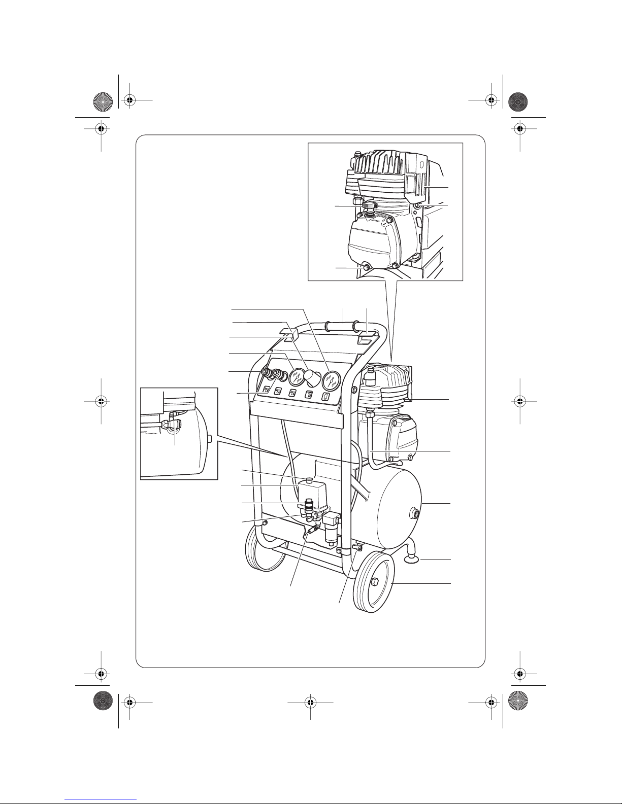
❏The safety valve 14 has been secured against
becoming altered. The blow-off pressure pre-set
by the manufacturer must not be changed.
❏No changes may be made on the machine by
the customer, in particular, the compressed air
reservoir 17.
❏Caution! Danger of burning! When the plant is
in operation, the unit and pressure tube 2 be-
come hot.
❏Do not place any inflammable objects in the vi-
cinity of the compressor.
❏Keep children and animals away from the op-
erating area and thereby prevent any injuries
being caused by equipment connected to the
compressor.
❏Do not operate the compressor without an air
filter.
❏Do not move the compressor if the reservoir is
under pressure.
❏Before commencing any work on the machine,
pull out the mains plug and ensure that the plant
is depressurised.
❏Use only original Würth parts and accessories.
GB
☞For further notes on safety refer to enclosed Sheet
0701 221.book Seite 12 Mittwoch, 2. Juni 2010 1:38 13

13
1 ON/OFF switch
2 Pressure lead
3 Compressor unit
4 Suction filter
5 Manual motor protection
6 Relief valve
7 Pressure switch
8 Handle
9 Oil filler opening/oil dipstick
10 Oil drain plug
11 Reduced Quick Coupling
12 Quick Coupling (not reduced)
13 Manometer for working pressure
14 Safety valve
15 Manometer for reservoir pressure
16 Non-return valve
17 Reservoir
18 Vibration damper
19 Condensation water drain cock
20 Wheels
21 Pressure reducer
22 Hook for electric cable
Not all of the accessories illustrated or described are in-
cluded as standard delivery.
The machine is designed for generating compressed
atmospheric air for commercial and industrial pur-
poses, i. e. for use as working air for driving tools,
as blowing air, e.g. for painting, or as control air for
plants and equipment.
For damage caused by usage other then intended,
the user is responsible.
– The intake air must be free from any aggressive
or inflammable particles.
– Before each operation, check the oil level using
the oil dip stick and, if necessary, replenish.
– It´s alway preferable to have longer air pipe,
than using extention cables, especially for models
K 290/K 410.
– Extension cables of up to 25 m in length must
have a cross-section of 1.5 mm2. Any lengths be-
yond this require 2.5 mm2. If the cross-section of
the conductor is too small, this will cause a volt-
age drop and there is no guarantee that the mo-
tor will start correctly. Cable reels must be fully
unwound.
– Never pull out the mains plug while the motor is
running. If the mains voltage fails, switch the ma-
chine off using the On/Off switch 1 and when
the voltage has been restored, switch on again.
– Do not exceed the maximum delivery output of
the machine (20 switchings per hour). At over-
load the pressure switch 7 is actuated. The ma-
chine is utilised optimally with a pause/operation
time ratio of 1 : 3.
The Würth machines of model series K 210, K 290
and K 410 are compressors with drive motors flang-
ed directly onto the compressor. Fresh air is drawn
in via the intake filter 4 serving as a sound absorber,
and compressed in the cylinder. The compressor
valve integrated in the cylinder head controls the
suction and emission of the air. The compressed air
flows into the compressed air reservoir via the pres-
sure lead 2 and the non-return valve 16.
The compressor functions in intermittent operation.
Upon reaching the maximum pressure the pressure
switch 7 switches the compressor off and when the
pressure falls to approx. 8 bar (for the K 210 ap-
prox. 6 bar) switches it on again.
Operating Controls
Use as Intended
Equipment Protection
Compressor Function
0701 221.book Seite 13 Mittwoch, 2. Juni 2010 1:38 13

14
Always use the correct supply voltage: The power
supply voltage must match the information quoted
on the tool identification plate. Tools with a rating of
230 V can also be connected to a 220 V supply.
Check the oil level on the oil dip-stick.
Installation
Install your compressor in a horizontal position in a
cool, dry, place exposed to as little dust as possible.
The maximum permissible angle of tilt is 15°. Pay spe-
cial attention to good cooling of the plant. This is main-
ly achieved by ensuring a free passage of fresh air.
It is important that the temperature at the location
does not fall below +5 °C and does not exceed
+40 °C. Devices and leads that give off heat should
be avoided in the environment.
Compressed air connection
– Connect the compressed air lead to the reduced
quick coupling 11.
– Loosen the locking ring on the pressure reducer
21 and set the required working pressure on the
turning grip:
– clockwise turn: working pressure increases,
– anti-clockwise turn: working pressure decreases.
– The following reference values apply for different
kinds of work:
Paint-spraying devices........................2 - 4 bar
Drive for pneumatic tools ....................5 - 7 bar
– Observe the information in the operating instruc-
tions of the consumers used.
– Secure the pressure reducer against unintention-
al alteration using the locking ring (or snap
switch).
– After use set the pressure reducer 21 back to “0”.
– All Models are equipped with an additional
quick coupling (not reduced) 12. Before connect-
ing more than one pneumatic tool to the com-
pressor, please check that the total air consump-
tion won´t be higher than the „effective delivery
quantity“ contemporary use of more than one
tool is not suggested.
Switching on
– Switch the compressor on using the On/Off
switch 1.
– The compressor is fitted with an automatic pres-
sure relief. If the rated pressure in the compressed
air reservoir 17 reaches 10 bar (for the K 210
8 bar), the motor is automatically switched off
and the pressure lead 2 between the compressor
and non-return valve 16 is vented. A pressure-
free re-start of the compressor is thereby guaran-
teed.
The pressure relief will cease to function if the
mains voltage fails during operation, or if the
mains plug is disconnected. The pressure relief
becomes effective again, however, if the com-
pressor on the pressure reducer 21 is set to “0”.
Switching off
– Switch the compressor off using the On/Off
switch 1.
Before commencing any work on the machi-
ne, discharge the air from the reservoir and
switch the machine off.
Always keep the machine clean.
Suction filter 4
Remove the filter and wash the sponge element with
a neutral detergent rinse and dry it carefully. If the
sponge element is damaged, replace it with a new
one.
Do not operate compressor without suction fil-
ter.
Initial Operation
Maintenance and Cleaning
0701 221.book Seite 14 Mittwoch, 2. Juni 2010 1:38 13

15
Draining the condensation
– Caution! The compressed air reservoir 17 is un-
der pressure. Place a collecting vessel under-
neath. Carefully open the condensation water
drain cock 19 on the base of the compressed air
reservoir by making a 1/2 turn and drain the
condensation.
– Check the condensation level regularly in the
transparent container of the pressure reducer 21.
It must not exceed the upper marking. For drain-
ing the condensation, the knob located on the un-
derside of the pressure reducer must be opened
a 1/2 turn under pressure.
Oil change (except oil free)
– As a basic rule the oil change should be carried
out under hot-running conditions.
– Place the collecting vessel underneath and open
the oil drain plug 10. Caution! Danger of burn-
ing from the hot oil!
– Close the oil drain plug 10 and fill up with oil of
class ISO 100 through the oil filler opening 9.
Never mix different oils.
Maintenance intervals
If the machine should fail despite the care taken in
manufacturing and testing, repair should be carried
out by a Würth MasterSERVICE agent.
For all correspondence and spare parts orders, al-
ways include the article number on the type plate of
the machine.
For the current spare parts list of this machine, log
into the Internet under “http://www.wuerth.com/
partsmanager” or ask for a copy at your nearest
Würth branch office.
Care - clean the cooling fins of
the cylinder and
pressure lead 2
regularly; clean the
manometer sight
glasses
Screwing connections - tighten once after 50
hours of operation
Checking the oil level - daily, or before each
use
Changing the oil -for the first time after 5
hours of operation
- regularly after 100
hours of operation,
however, at least once
every 6 months
Draining the
condensation
- at least weekly
- if required, daily
Checking the intake
filter
- weekly
Cleaning the intake
filter
- monthly, and more
often if exposed to
large amounts of dust
Changing the intake
filter
- if extremely dirty or
damaged
Cleaning the non-return
valve
- every 2 years
Warning! discharge the
reservoir pressure!
Recommended check
according to pressure
reservoir instructions
-
-
every 5 years - internal
check
every 10 years -
pressure check
0701 221.book Seite 15 Mittwoch, 2. Juni 2010 1:38 13

16
The compressor fails to start.
– The motor protector 5 is actuated. > Disconnect power supply, and wait few minutes.
Press the motor-protector 5 and then press the
On/Off switch 1 to switch on the compressor. If
the motor protection is actuated again, contact
the customer service.
– The manometer 15 shows a pressure greater
than 7.5 bar (for the K 210 5 bar) (cutting-in
pressure).
> Release pressure until the pressure switch 7
switches on.
– Mains voltage fails. > Check the electrical leads, etc.
Compressor runs uninterruptedly.
– Intake filter 4 is dirty. > Clean filter or replace.
– The compressor is overloaded. > Reduce the compressed air requirement.
– Leakage in the subsequent lead system. > Eliminate leakage.
– Compressor is defective. (Pressure switch faulty). > Contact the customer service.
The compressor runs for a short time when reaching the cutting-in pressure but then automatically
switches off.
– The compressor was not de-pressurised because
the electrical feed was interrupted during opera-
tion.
> Switch the compressor off using the On/Off
switch 1 and then switch it on again.
– On/Off switch 1 is defective. > Contact the customer service.
– The length of the mains connection lead is not
permissible or the conducting cross-section is too
small.
> Lead length max. 25 m with a cross-section of
1.5 mm2.
At standstill, compressed air escapes for a longer period through relief valve 6 under pressure switch 7,
until the cutting-in pressure is reached.
– Non-return valve 16 has a leak or is defective. > Contact the customer service.
During operation compressed air escapes through relief valve 6.
– Relief valve 6 has a leak. > Contact customer service.
Compressor often switches on.
– Condensation water in the compressed air reser-
voir 17.
> Drain condensation water.
– Compressor is overloaded. > Reduce compressed air requirement.
– Reduced performance due to worn valve plate. > Contact customer service.
Safety valve 14 blows off.
– Reservoir pressure is greater than the opening
pressure of the safety valve 14.
– Pressure switch 7 must be re-set or changed;
contact customer service.
– Safety have faulty, it must be replaced. Contact
customer service.
Error Detection
0701 221.book Seite 16 Mittwoch, 2. Juni 2010 1:38 13

17
Power tools, accessories and packaging should be
sorted for environmental-friendly recycling.
Only for EC countries:
Do not dispose of power tools into
household waste!
According to the European Directive
2002/96/EC on waste electrical
and electronic equipment and its in-
corporation into national law, power tools that are
no longer suitable for use must be separately collect-
ed and sent for recovery in an environmental-friend-
ly manner.
For this Würth tool, we provide a warranty in
accordance with statutory/country-specific regula-
tions from the date of purchase (proof of purchase
by invoice or delivery note). Damage that has
occurred will be corrected by replacement or repair.
Damage caused by normal wear, overloading or
improper handling is excluded from the warranty.
Claims can be accepted only when the machine is
presented undisassembled to a Würth branch office,
your Würth sales representative or a customer serv-
ice agent for Würth pessure air and power tools.
Measured values determined according to
2000/14/EG.
Wear hearing protection!
We declare under our sole responsibility that this
product is in conformity with the following standards
or standardization documents: EN 1012-1,
EN 60 204-1, EN 60 335-1, EN 61 000-6-3/4
according to the provisions of the regulations
2006/42/EG, 2000/14/EG, 2006/95/EG,
2004/108/EG, 2009/105/EG.
Technical file at:
Adolf Würth GmbH & Co. KG, Abt. PFW
74650 Künzelsau
N. Heckmann A. Kräutle
Chairman of General Manager
Adolf Würth
GmbH & Co. KG
Künzelsau: 10.05.2010
Disposal
Warranty
Sound pressure level Sound power level
LwA
K 210: 79 dB (A) 94 dB (A)
K 290: 79 dB (A) 97 dB (A)
K 410: 81 dB (A) 97 dB (A)
Noise/Vibration Information
Declaration of Conformity
Subject to change without notice
0701 221.book Seite 17 Mittwoch, 2. Juni 2010 1:38 13
This manual suits for next models
2
Table of contents
Popular Air Compressor manuals by other brands

Michelin
Michelin MBL 6V2/1100 user guide

Kaishan
Kaishan KRSD Series instruction manual

VONROC
VONROC CR503DC Original instructions

Clarke
Clarke PIONEER 220 Operating & maintenance instructions

Eaton Compressor
Eaton Compressor POLAR AIR PP05H080I1 user manual

L&W Compressors
L&W Compressors LW 200 B MC operating instructions