Doc 1 – Issue 2 Page 2 of 16
CONTENTS
CONTENTS...........................................................................................................................2
GENERAL INFORMATION AND SAFETY SUMMARY ...................................................3
Safety Precautions ..............................................................................................................3
Introduction........................................................................................................................3
Functional and Equipment Description of System...............................................................3
CHAPTER 1 ..........................................................................................................................4
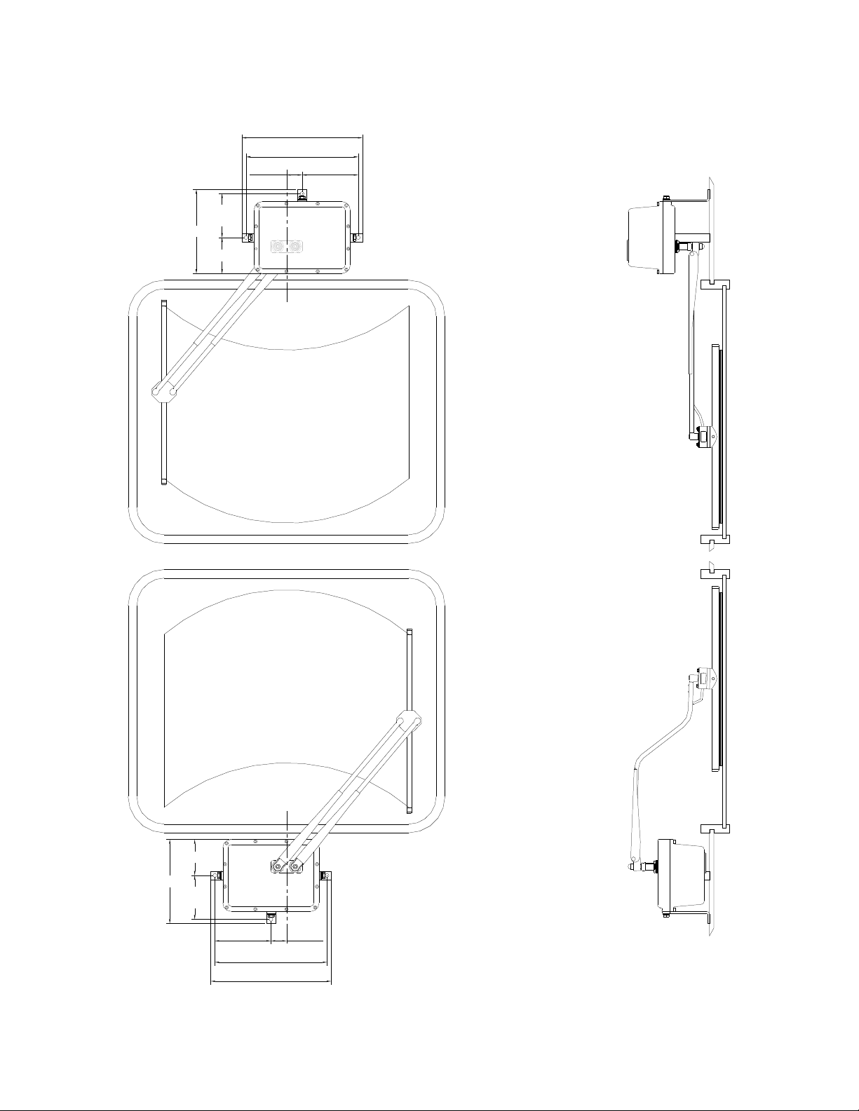
Wiper Motor Assembly...................................................................................................4
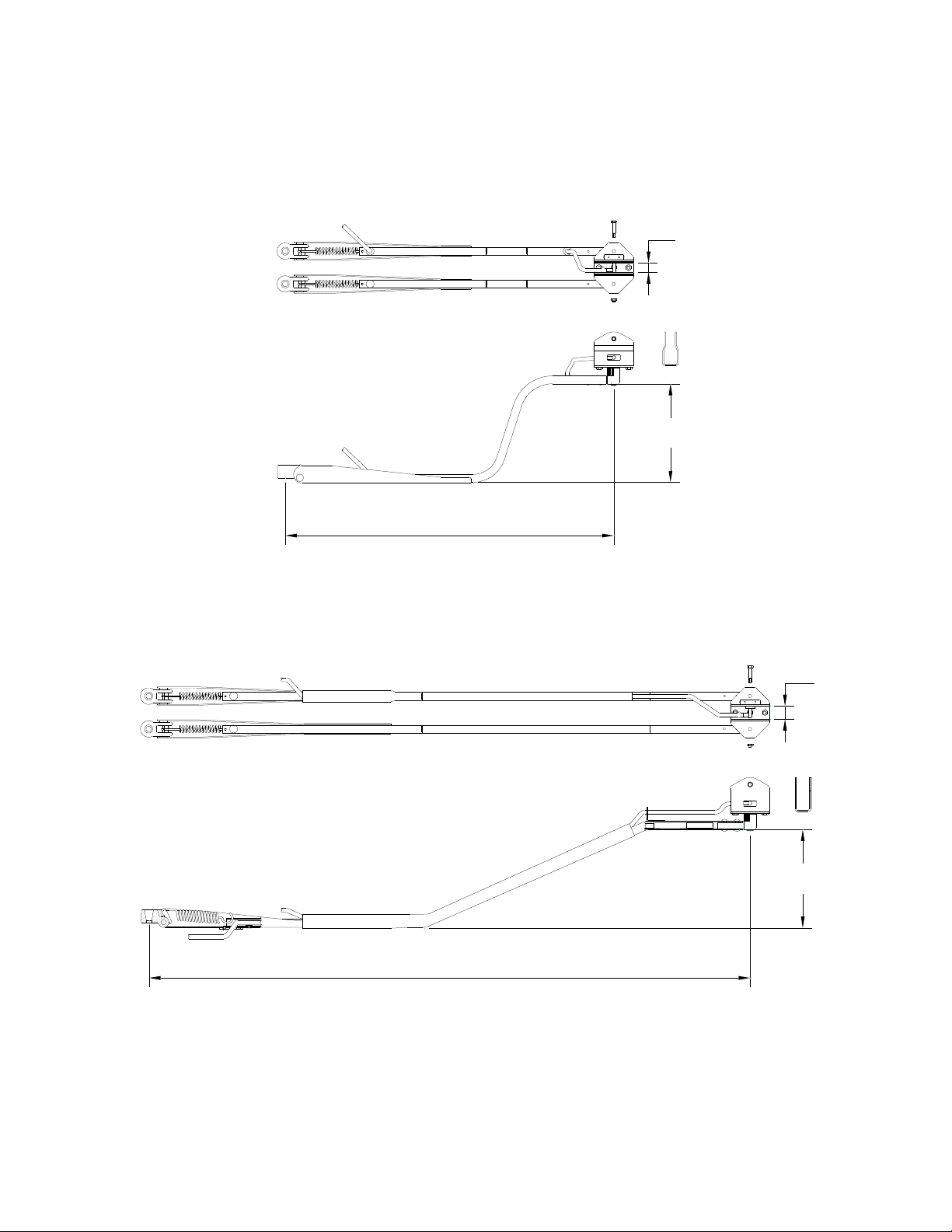
1850 0 – range arms ...............................................................................................................6
Cranked Arms – Outboard Facing Spindles ........................................................................6
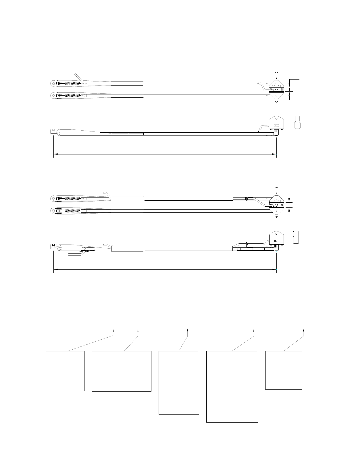
1850 1 – range arms ...............................................................................................................7
Straight Arms – Inboard Facing Spindles............................................................................7
CHAPTER 2 ..........................................................................................................................8
Installation Instructions.......................................................................................................8
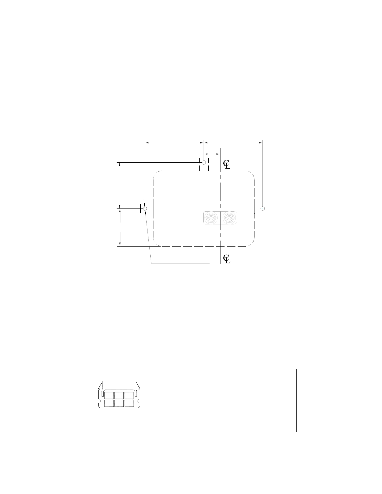
Drilling Diagram ............................................................................................................8
Fitting the Wiper Motor Assembly..................................................................................8
Fitting the Wiper Blade...................................................................................................9
Fitting the Wiper Arm Assembly ....................................................................................9
CHAPTER 3 ........................................................................................................................10
Maintenance .....................................................................................................................10
Introduction ..................................................................................................................10
Safety Precautions ........................................................................................................10
Scheduled Maintenance Action Check ..........................................................................10
Table 1 .........................................................................................................................10
CHAPTER 4 ........................................................................................................................11
Troubleshooting................................................................................................................11
Introduction ..................................................................................................................11
Safety Precautions ........................................................................................................11
Troubleshooting Procedures..........................................................................................11
Table 2 .........................................................................................................................11
Table 2 - Continued ......................................................................................................12
CHAPTER 5 ........................................................................................................................13
The Extractor....................................................................................................................13
Switch Operation – Multi-Switch......................................................................................13
SPARES LIST......................................................................................................................14