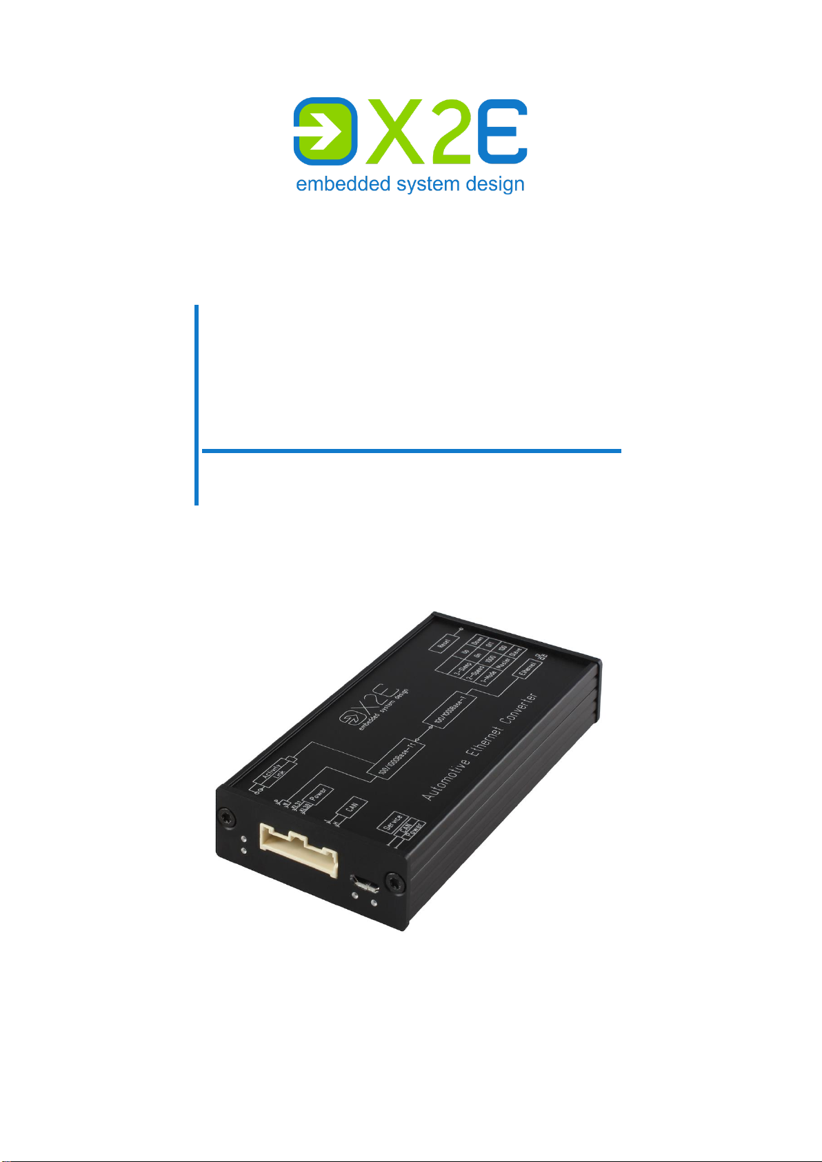
User Manual Automotive Ethernet Converter
3
Table of contents
Introduction.............................................................................................4
Intended use............................................................................................4
Delivery contents .....................................................................................4
General safety instructions......................................................................5
Product overview.....................................................................................5
Identification.............................................................................................7
Connections and controls ........................................................................8
Installation.............................................................................................11
Mounting................................................................................................11
Connecting.............................................................................................11
Configuration and firmware update .......................................................13
Install XORAYASuite................................................................................13
Start Gateway configuration ..................................................................14
Connect converter..................................................................................15
Change configuration.............................................................................15
Update firmware.....................................................................................16
Disconnect converter.............................................................................16
Cleaning................................................................................................17
Repair...................................................................................................17
Disposal................................................................................................17
Appendix...............................................................................................18
Technical specifications.........................................................................18
Pin assignments.....................................................................................18