manuals.online logo
Brands
  1. Home
  2. •
  3. Brands
  4. •
  5. Xantech
  6. •
  7. Laboratory Equipment
  8. •
  9. Xantech INJ94 User manual

Xantech INJ94 User manual

08900870 rev. C 12-7-00


11.00"
fold here
8.50"
INSTALLATION INSTRUCTIONS
Xantech Corporation •12950 Bradley Avenue • Sylmar CA 91342 • (818) 362-0353 • www.xantech.com • PRINTED IN CHINA
DESCRIPTION
The INJ94 injects and the CPL94B extracts IR control signals on the same coaxial cable that
carries TV or other RF signals, using the patented Xtra Link™ principle.
MODELS
INJ94 INJECTOR & CPL94B COUPLER
CPL94B Coupler:
• "F" coaxial connector jacks for SAT/VCR
and REMOTE TV signals.
• Two 3.5mm EMITTER mono mini jacks,
with 470 Ohm series resistors, for quick
connection of two Xantech single or dual
emitters.
• Dimensions: 2-3/16" x 1-3/8" x 7/8" (case).
SPECIFICATIONS
INJ94 Injector:
• "F" coaxial connector jacks for TV and
INPUT signals.
• 3.5mm IR RCVR stereo mini jack for quick
connection of Xantech IR Receivers having
3.5mm stereo mini plugs.
• 2.1mm +12 V jack for connection of the
Xantech 781RG Power Supply.
• Dimensions: 2-3/16" x 1-3/8" x 7/8" (case).
TROUBLE SHOOTING
A. Perhaps the most common problem is
stray IR or RF interference entering IR
receivers, preventing proper operation of
the controlled equipment.
Examples of such interference are:
• Fluorescent, Compact Fluorescent,
Neon or Halogen lights, Neon Art, or
light dimmers.
• Direct or reflected sunlight.
• Infrared security sensors (active type).
• RF radiation from TV sets that may be
close to IR Receivers.
It may be necessary to move either the
interfering source or the IR receiver to
achieve proper operation. Sometimes
the Xantech Sun Filters will help.
B. If the IR receivers must operate in the
vicinity of electronically ballasted Compact
Fluorescent lamps or sunlight conditions,
use Xantech models 291-80 or 780-80 IR
receivers. These are specifically designed
to reject most of this type of interference.
C. Check for shorts or opens anywhere
between the IR receivers in the remote
rooms and the emitters at the controlled
equipment.
• Remember, you must have DC
continuity all the way from the IR (IR
RCVR) jacks on the Injectors, through
the coax cables to the IR (emitter) jack
on the coupler, without shorts to ground.
• Use a Xantech Test-IR plugged into
the IR (emitter) jack on the coupler to
verify that the IR signal is being received
from each room.
• If necessary, use a multimeter in the
low Ohms range to check for continuity,
shorts, opens, etc.
• Check for open emitters by substituting
a known good emitter.
D. If a given component still does not work,
reposition the emitter. It may not be located
directly over the component’s IR (infrared)
receiving "window". Consult the owner's
manual of the unit or the manufacturer for
the exact location of the infrared "window".
+12 V
IR
RCVR
TV
INPUT
INJ94 INJECTOR
Fig. 2 CPL94B Coupler
EMITTER
REMOTE TV
SAT/VCR
CPL94B COUPLER
EMITTER
Located in Remote Rooms, the INJ94 injects the remote control signal into the room-to-room
coaxial cable (along with the TV signal) and passes it to a CPL94B or CPL10 Coupler in the
Main Room or equipment area. It is designed specifically so that Xantech IR Receivers
having 3.5mm stereo mini plugs may be plugged in directly to the IR RCVR jack. The 2.1mm
+12 V coaxial jack also provides quick connection of the Xantech 781RG power supply.
Located in the Main Room or equipment area, the CPL94B extracts the remote control signal
from the coaxial cable and passes it to the emitters that control the source equipment. Any
of the Xantech single or dual emitters may be plugged directly into the 3.5mm mono mini
EMITTER jacks, in any combination, for control of up to four components.
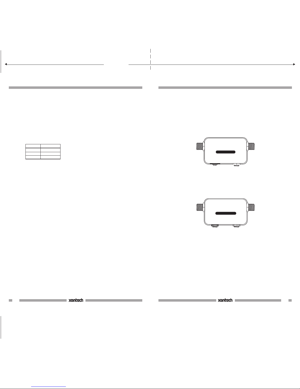
Fig. 1 INJ94 Injector
Pg 4 Pg 1
CIRCUIT ITEM
GROUND
SIGNAL
+ 12 V
PLUG
RING
TIP
SLEEVE
Fig. 5
ADVANCED MULTIROOM SYSTEMS
(cont'd)
2. Each IR receiver must be locally powered
by a 781RG Power Supply as shown.
3. IR RCVR jack connections for the INJ94.
Should you wish to make your own cus-
tom connections to a mating 3.5mm ste-
reo mini plug for this jack, follow the termi-
nal identifications given in the table, Fig.
5, below:
4. Note that model 203-00 DC Blockers are
used on the two coax leads going to the
two TV sets in the rooms
not
having IR
receivers. This is a
must
to prevent the
RF inputs on the two TV sets from "short-
ing out" the IR control signal.
5. If an RF amplifier(s) is used anywhere in
the line of coaxial cable between the
CPL94B Coupler and the INJ94 or CPL10
Injectors, you
must
use a Xantech BY-
PASS94 KIT to route the IR control sig-
nals around the amplifier(s).
Where possible, place RF amplifiers ahead
of the CPL94B Coupler, as shown in Fig.
4, instead of using a bypass kit.
6. Fig. 4 shows four components being
controlled using two 286M dual emitters.
This is the maximum number of
components controllable with the CPL94B.
If you wish to control more, use the CPL10
instead, along with a suitable connecting
block, such as the 789-44 or 791-44. See
the CPL10 installation instructions for
details.
7. For information on how to connect and
configure modulators and RF amplifiers,
refer to Channel Plus®technical
information.
INSTALLATION INSTRUCTIONS, INJ94 & CPL94
XANTECH P/N 08900870C
INK: BLACK
MATERIAL: 20 LB. MEAD BOND
SIZE: 5.500" WIDE X 8.500" HIGH
Page 1 of 2
08900870C
08900870 rev. C 12-7-00


11.00"
fold here
8.50"
INSTALLATION
FIG. 3 illustrates a typical installation using
two INJ94's and a CPL94B in a three room
system.
When configuring these types of systems,
keep the following factors in mind:
1. Room-to-room coaxial cable lengths,
exclusive of RF signal considerations, may
be up to one mile in length, using RG-6, for
successful IR signal transmission.
2. When configuring multiple rooms, be sure
the RF splitters used are DC passing
types, such as Xantech Models 200-00
(2-way) and 202-00 (4-way). Refer to
Figs. 3 and 4.
Fig. 3 A Typical 3-Room System
TV
Two Remote Rooms
not
configured
with IR receivers.
(See item 4, pg 4).
480-00
CPL94B
Coupler
(1 location)
202-00
4-way RF Splitters
DC Passing
RF
AMP
Satellite Receiver Laser Disc Player VCR Cable Box
2512
2-way
Combiner
Modulator
(3-Input)
A/V Patch
Cords
INJ94
Injectors (3)
TV TV
TV TV TV TV
TV
CB12
CB12
CB12
200-00
2-way RF splitter
DC Passing
291-80
480-00 480-00
291-10 490-30
781RG
Power
Supplies (6)
CPL10
Couplers (3)
Six Remote Rooms, each configured with IR receivers.
203-00
DC Blockers (2).
(See item 4, pg 4).
RF Signal
IR Signal
286M
Dual Blink-IR™
Mouse Emitter Assembly
286M
Dual Blink-IR™
Mouse Emitter
Assembly
EMITTER
REMOTE TV
SAT/VCR
CPL94B COUPLER
EMITTER
+12 V
IR
RCVR
TV INPUT
INJ94
+12 V
IR
RCVR
TV INPUT
INJ94
+12 V
IR
RCVR
TV INPUT
INJ94
IR
RF RF/IR
CPL10
IR
RF RF/IR
CPL10
IR
RF RF/IR
CPL10
IN OUT
Fig. 4 Advanced Multiroom System
ADVANCED MULTIROOM SYSTEMS
Fig. 4 illustrates an advanced system using
a variety of connection and control tech-
niques typical of complex multiroom installa-
tions. It is configured as follows:
1. Both INJ94 Injectors and CPL10 Couplers
are used in the remote rooms with various
Xantech IR Receivers.
As a rule of thumb, use the CPL10 with the
CB12 Connecting Block when using
Xantech 3-terminal IR receivers or
keypads, such as the 480-00 Dinky Link,
730-00 Smart Pad, etc. Use the INJ94
when using Xantech IR receivers equipped
with a 3.5mm quick-connect stereo mini
plug, such as the 291-00 Hidden Link and
the 490-30 Micro Link.
Pg 2 Pg 3
MAIN ROOM
RF IN OUT TO TV
RF IN OUT TO TV
TV SIGNAL PATH
IR REMOTE CONTROL PATH
Hand Held
Remote
REMOTE ROOM 2
RF IN
2ND
TV
Hand Held
Remote
REMOTE ROOM 1
RF IN
3RD
TV
Satellite Dish
286M
Dual Blink-IR™
Mouse Emitter Assembly
Coaxial Cable
Place emitters on
the IR sensor
window on front
panel of each
controlled unit.
Emitter
SATELLITE
RECEIVER
(Back Panel)
VCR
(Back Panel)
Emitter
IR Sensor Windows
(Front Panel)
Coaxial Cable
Coaxial Cable
Coaxial Cable
Coaxial Cable
Room-to-Room Coaxial Cables
200-00
2-Way RF Splitter
DC Passing
Coaxial Cable
To 120 V AC
(unswitched)
291-00
IR RECEIVER
Coaxial Cable
INJ94
INJECTOR
781RG
Power Supply
Local
TV
RF IN
Coaxial
Cable CPL94B
COUPLER
(included)
200-00
2-Way
RF Splitter
Spare jack
for additional
emitter(s),
if needed.
+12 V
IR
RCVR
TV INPUT
INJ94 INJECTOR
+12 V
IR
RCVR
TV INPUT
INJ94 INJECTOR
EMITTER
REMOTE TV
SAT/VCR
CPL94B COUPLER
EMITTER
IN
OUT
OUT
IN
OUT
OUT
To 120 V AC
(unswitched)
781RG
Power Supply
291-00
IR RECEIVER
INJ94
INJECTOR
Page 2 of 2
08900870C

This manual suits for next models

1

Popular Laboratory Equipment manuals by other brands

Keeler KSL-H Instructions for use

Keeler

Keeler KSL-H Instructions for use

Hanna Instruments HI97705 instruction manual

Hanna Instruments

Hanna Instruments HI97705 instruction manual

Selecta PRESOCLAVE III 50L manual

Selecta

Selecta PRESOCLAVE III 50L manual

SteriFeed S90 Installation and maintenance manual

SteriFeed

SteriFeed S90 Installation and maintenance manual

Germozap L100254 Instruction guide

Germozap

Germozap L100254 Instruction guide

Thermo Scientific Sorvall RC6 Plus instruction manual

Thermo Scientific

Thermo Scientific Sorvall RC6 Plus instruction manual

Funke Gerber CryoStar I manual

Funke Gerber

Funke Gerber CryoStar I manual

Biotage Selekt user manual

Biotage

Biotage Selekt user manual

AB Sciex 4500 Series System user's guide

AB Sciex

AB Sciex 4500 Series System user's guide

NuAire LabGard ES NU-565-400 Operation & maintenance manual

NuAire

NuAire LabGard ES NU-565-400 Operation & maintenance manual

caron FLTR301 quick start guide

caron

caron FLTR301 quick start guide

Yamato RE202-A/212-A instruction manual

Yamato

Yamato RE202-A/212-A instruction manual

BioCision XT Starter Instructions for use

BioCision

BioCision XT Starter Instructions for use

Integra ASSIST PLUS operating instructions

Integra

Integra ASSIST PLUS operating instructions

Metrohm 893 manual

Metrohm

Metrohm 893 manual

UMS HYPROP Operation manual

UMS

UMS HYPROP Operation manual

BEHR InKjel P user manual

BEHR

BEHR InKjel P user manual

IKA RO 5 operating instructions

IKA

IKA RO 5 operating instructions

manuals.online logo
manuals.online logoBrands
  • About & Mission
  • Contact us
  • Privacy Policy
  • Terms and Conditions

Copyright 2025 Manuals.Online. All Rights Reserved.