ENDEVCO 2911 User manual

IM2911
Revision A
28 September 2007
DOCUMENT SUBJECT TO U.S. EXPORT CONTROLS. COMPLIANCEAPPROVAL REQUIRED PIOR TO DISTRIBUTION.
MODEL 2911
HIGH FREQUENCY SHAKER ASSEMBLY
INSTRUCTION
MANUAL
San Juan Capistrano, California, U.S.A.

IM2911
Revision A
28 September 2007
DOCUMENT SUBJECT TO U.S. EXPORT CONTROLS. COMPLIANCEAPPROVAL REQUIRED PIOR TO DISTRIBUTION.

ENDEVCO 2911
INSTRUCTION MANUAL
IM2911
Page C-1
TABLE OF CONTENTS
SECTION 1: DESCRIPTION PAGE
1. EQUIPMENT DESCRIPTION 1-1
2. EQUIPMENT USE 1-1
SECTION 2: CONTROLS AND CONNECTORS
1. INTRODUCTION 2-1
SECTION 3: OPERATING INSTRUCTIONS
1. UNPACKING AND INSPECTION 3-1
2. INSTALLATION 3-1
3. CHECKOUT 3-1
4. OPERATION 3-1
SECTION 4: THEORY OF OPERATION
1. THEORY OF OPERATION 4-1
SECTION 5: MAINTENANCE AND CALIBRATION
1. MAINTENANCE 5-1
2. CALIBRATION 5-1
3. TROUBLESHOOTING GUIDE 5-1
4. REPAIR 5-2
5. FACTORY SERVICE 5-2
SECTION 6: ACCESSORIES
1. ACCESSORIES INCLUDED 6-1
2. ACCESSORIES OPTIONAL 6-1
SECTION 7: DRAWINGS AND DIAGRAMS
1. GENERAL 7-1
2.DRAWINGS7-2

ENDEVCO 2911
INSTRUCTION MANUAL
IM2911
Page 1-1
SECTION 1
DESCRIPTION
1. EQUIPMENT DESCRIPTION
The ENDEVCOModel 2911 is a high frequency shaker designed to test a wide variety of accelerometers on the market
today. The 2911 is equipped with a thermally stable reference accelerometer as an integral part of the armature to give
accurate readings over a wide range of frequencies and operating environments. The armature is made of Beryllium,
which is quite stiff and light. This combination results in a resonant frequency around 40 kHz. This helps give the 2911 its
wide operating frequency range in a small, compact and affordable package.
The armature is similar to part of an electric motor, or voice coil that is held concentric by an air bearing operating around
20 PSI. The air maintains the armature relative position to the shaker body, while providing cooling for coil via the
armature. This translates to low transverse motion of the shaker. The accelerometer is anENDEVCO2270M18
ISOTRONwith low thermal drift that makes this shaker the best value on the market today.
2. EQUIPMENT USE
The 2911 is designed for laboratory use only. Due to the close tolerances between the armature and the body, any
foreign materials bigger than a few thousandths of an inch inside the air bearing can degrade shaker performance. It is
recommended that this shaker never be used in a hostile environment and covered when not in use.
Never attempt to operate the shaker without an adequate air supply, this will damage the shaker and void the warranty.
The air supply must be filtered for water and oil, as well as particles greater than 10 microns in size. Dry nitrogen can be
used. If a bottle of gas is used, be aware that there always is a leak on the system and must be turned off at the bottle
when not in use to conserve gas.
The armature is suspended between three rubber bands visible on the top of the shaker. These can be used to make
minor adjustments to the armature height relative to the shaker body. In the event that the armature sits too low in the
shaker due to a relatively heavy accelerometer placed on it, turning the vertical screws with the washers that the rubber
bands are attached to can raise the armature height. Raise all three evenly for best results, until the top of the armature
is at the center of its vertical travel between the mechanical limits.
If during a test, both the reference and UUT waveforms are distorted, the rubber bands should be adjusted first to correct
the problem. The fact that both are distorted is an indication that the armature could be maladjusted. Clipping of
waveforms may be an indication of improper height adjustment (previous paragraph) or excessive drive signal.
Mounting an accelerometer correctly involves the application of a thin layer of the acoustic couplant (optional accessory) to
mounting surfaces and application of accelerometer’s manufacturer’s recommended torque specification.

ENDEVCO 2911
INSTRUCTION MANUAL
IM2911
Page 2-1
SECTION 2
CONTROLS AND CONNECTORS
1. INTRODUCTION
The Model 2911 has an input connector for the drive signal. See Section 7for more detailed shaker connection
information. The ¼ inch plumbing connector is for clean dry air free of oil, water or particles bigger than 10 microns.
Shaker should always have air applied before operation is attempted. The cable coming out of the shaker is the output of
the reference accelerometer.

ENDEVCO 2911
INSTRUCTION MANUAL
IM2911
Page 3-1
SECTION 3
OPERATING INSTRUCTIONS
1. UNPACKING AND INSPECTION
Remove the top layer of packing material exposing the shaker. Invert shipping container while supporting the shaker.
Allow the shaker to slide out of the box slowly to avoid damage. Visually inspect the exterior of the shaker for any signs of
mishandling. Dings and dents on the exterior surface may indicate rough handling.
Gently grab the armature between two fingers and attempt to move the armature up and down. The armature may bind
a little, this is normal, but it should move up and down without applying much force. If the armature does not move easily
after applying air to the shaker and the armature still binds, thenshaker should be returned to ENDEVCOas soon as
possible for repair.
2. INSTALLATION
The shaker can be installed on any hard, level, stationary surface. An optional isolator is useful in reducing any effects
vibrations from the mounting surface might cause.
The shaker may also be “hung” from the square spacer plate spacer with appropriate hardware and support.
3. CHECKOUT
After connecting the air, 25-pin cable and the reference transducer the shaker is ready for checkout. If the shaker is
connected to an AACS system, then appropriate changes to the system configuration file, exciter definitions and model
test definitionsare required for the system to recognize the shaker. (Consult IM68357 for specific instructions.)Then
selecting and starting a sweep that specifies the 2911 shaker to be used will activate the shaker. After the audible “click” of
the air solenoid, push down on the armature slightly. If it moves freely this means that the system applied the air and the
system configuration and the connections are correct. If not, read the IM68357 sections about “System Configuration
Editor”, “Exciter Definitions” and “Model Test Definitions”.
The UUT goes to the PE/IEPE input on the front of the “Calibration Input Panel”. Upon actual starting of the test, a
sinusoid wave should appear in REF window, if not check to see if the reference input specified in the “System
Configuration Editor’ and where the reference transducer are connected to, see if they are in agreement.
Without an AACS, check out is as simple as applying air, connecting to a power amp through the 25-pin connector and
applying a small amplitude signal at first to establish the fact that the shaker responds to an input. Excessive signal input
will drive the shaker to the stops, indicated by an audible thumping. If this should occur, reduce the signal immediately.
4. OPERATION
Operation is accomplished by monitoring the reference accelerometer while applying a sine wave to the shaker. This is
done automatically by the AACS system. The reference accelerometer determines the acceleration that the Unit Under
Test (UUT) is subjected too. Comparing the reference accelerometer response to the UUT response determines the
characteristics of the UUT.
The reference accelerometer is operated with a constant current source of usually 4mA. The actual signal output is
compliance voltage changing to maintain the 4mA current. All of this is transparent to the AACS user.

ENDEVCO 2911
INSTRUCTION MANUAL
IM2911
Page 4-1
SECTION 4
THEORY OF OPERATION
1. THEORY OF OPERATION
The shaker armature has a coil around it inside of a permanent magnetic field. When current is passed through the coil an
opposite or attractive magnetic force field is generated depending on the phase of the drive signal. The interaction of the
magnetic fields is what causes the armature to move up and down. The armature is similar to part of an AC motor.
The reference accelerometer is mounted on the underside of the surface that accepts accelerometers under test. This is
required to accurately measure the acceleration seen by the Unit Under Test (UUT). The reference accelerometer
calibration is traceable to National Institute of Standards & Technology (NIST). Both traceability and mounting proximity
are necessary to ensure a valid measurement.

ENDEVCO 2911
INSTRUCTION MANUAL
IM2911
Page 5-1
SECTION 5
MAINTENANCE/CALIBRATION
1. MAINTENANCE
Maintenance is quite simple. If you notice a change in your Reference Accelerometer waveforms this is what to do. Apply
air pressure and manually move the armature up and down trying to feel if the armature is rubbing on the air bearing. If
so, it needs to be re-aligned and/or cleaned.
For cleaning, remove the stator and air-bearing by removing the three screws so the stator can be lifted away from the
base. Look for any visible signs of scoring on the armature surface. If there is, look on the corresponding surface in the
magnet base for foreign objects and removed them as required. Cleaning of the surfaces can be accomplished with
alcohol or some other low residue solvent. After cleaning, the shaker needs to be re-assembled and re-aligned.
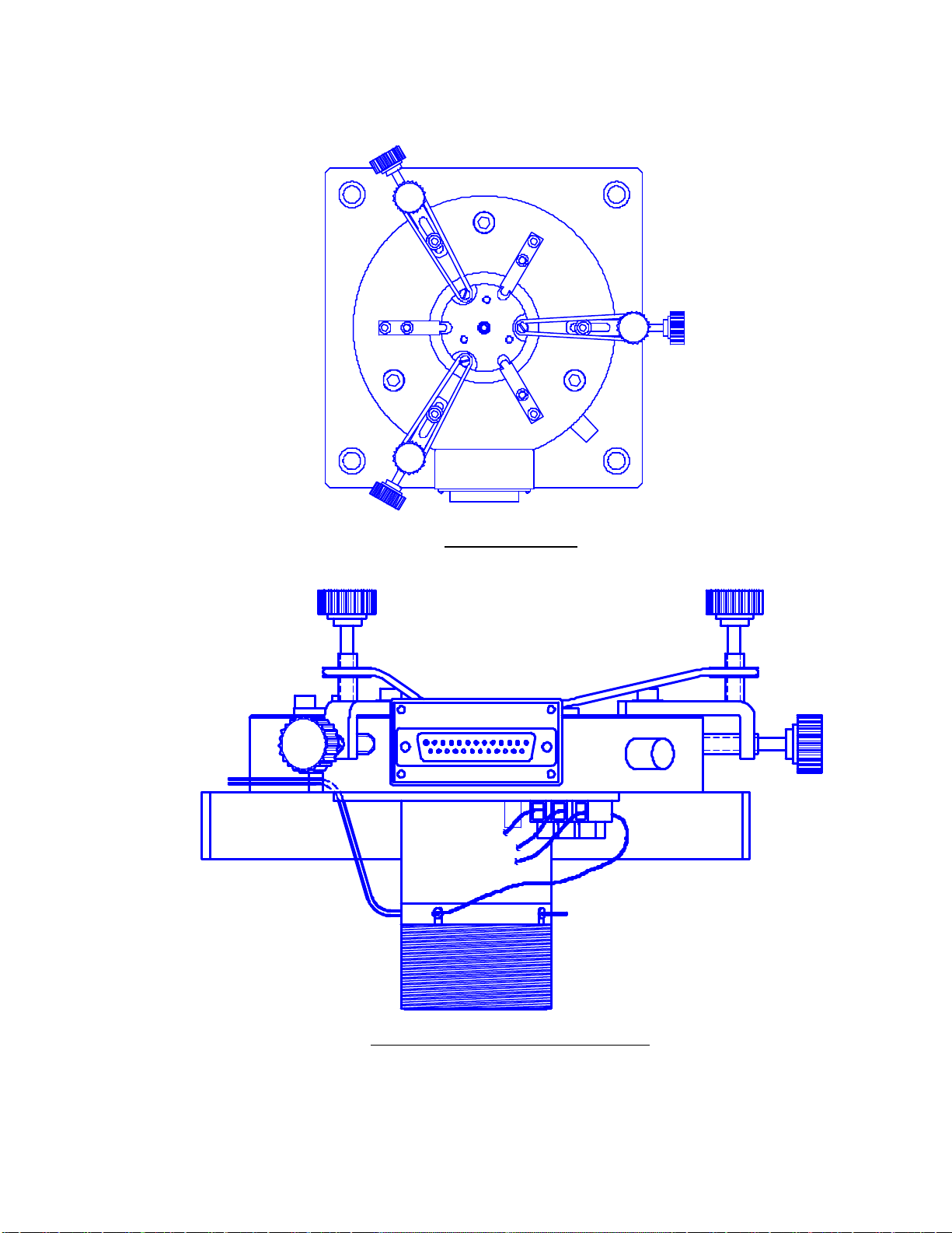
To do this replace the stator assembly and install the three screws on the top (see Figure 2) of the shaker. With air
pressure applied move the stator around until the armature moves up and down freely when pushed down with a finger.
The air pressure should push the armature up to its mid position when adjustment is correct. Then tighten the screws
incrementally to maintain the stator’s position, while checking for friction free motion. When all the screws are tightened,
check the armature for freedom of movement. Repeat if the armature does not move freely with air applied. After
adjusting, or if there is a noticeable change, a shaker characterization should be performed. This is a function performed
on the AACS system.
The Shaker Characterization procedure does not affect calibration. It merely measuresresponses to known electrical
inputs to allow the system to better guess what levels of drive signal to provide to accomplish any given acceleration
needed for any given test. Further adjustment to the drive signal is done by means of feedback from the REFERENCE
accelerometer to give the exact level of drive needed for the desired level of acceleration.
2. CALIBRATION
Calibration is accomplished by means of a “Transfer Calibration” on the AACS model 68357. Instructions for this are in
the IM68357 document supplied with the system. Other means of calibration may not be traceable to the National Institute
of Standards & Technology (NIST) and are not recommended. If you lack the equipment and/or the expertise to calibrate
this instrument, return it to ENDEVCO for calibration.
Calibration is recommended every 6 to 12 months.
3. TROUBLESHOOTING GUIDE
Symptoms Checks
No output from reference accel 4mAcurrent/voltage applied.
Shaker does not shake Air applied, signal applied. Check by hand for movement.
Does it bind? Does it drag?
Air and signal applied Check for open armature,see Figure 1.
and shaker does not shake Normal resistance is 3 O
Power line freq. output Check for accel case ground to armature
Audible thumping Check armature hitting mechanical stops.
Adjust mounting surface to 6mm above air-bearing.

ENDEVCO 2911
INSTRUCTION MANUAL
IM2911
Page 5-2
4. REPAIR
Repair of the shaker is usually not possible in the field. In the event of a broken wire inside the shaker or something
similar to this, the user can fix it without any problems. The simple design of the shaker has few moving parts and
therefore does not lend itself to many “simple fixes”.
Access to component parts is gained by removal of the three cap head screws that secure the unit's top plate. This
reveals all the moving parts. Further disassembly will not reveal any more user serviceable parts. If no physical damage
can be seen at this point, then the unit should be returned to ENDEVCO.
5. FACTORY SERVICE
If serious trouble occurs, and the instrument cannot be made to perform specifications, return the shaker to the factory. A
detailed statement describing the fault noted should always accompany it.
ENDEVCO warrants each new instrument to be free from defects in material and workmanship for one year from the
date of sale to the original purchaser. This warranty does not extend to units that have been mistreated, used in violation
of Endevco recommendations, or to units that have been altered or repaired outside of the ENDEVCO factory. Defects
covered by this warranty will be corrected at no charge when the unit is delivered to the factory with all transportation
charges prepaid. If, upon examination, it is found that a defect is not within the scope of this warranty, a statement of
repair charges and a request for authorization to proceed with repair will be submitted to the purchaser.
Address all shipments and correspondence to:
Endevco
Technical Services Dept.
30700 Rancho Viejo Rd.
San Juan Capistrano, CA 92675

ENDEVCO 2911
INSTRUCTION MANUAL
IM2911
Page 6-1
SECTION 6
ACCESSORIES
1. ACCESSORIES INCLUDED
The following accessory items are included with the Model 2911:
QTY. PART NUMBER DESCRIPTION
115071 Adapter Stud, 1/4-28 UNF to 10-32 UNF
114159-1Adapter Bushing, 1/4-28 UNF to 10-32 UNF
114159-2Adapter Bushing, 1/4-28 UNF to 6-32 UNC
114159-4Adapter Bushing, 1/4-28 UNF to 2-56 UNC
1EHM374 Hex Wrench, 1/8 in.
1EHM1020 Hex Wrench, 1/4 in.
2. ACCESSORIES OPTIONAL
The following accessories for use with the Model 2911 are available from ENDEVCO:
QTY. PART NUMBER DESCRIPTION
134699 Isolation Mounting Kit *
114159-3Adapter Bushing, 4-40 UNC
114159-5Adapter Bushing, 4-48 UNF
114159-6Adapter Bushing, 8-32 UNC
114159-7Adapter Bushing, M3 x 0.5
1EHX268 Acoustic Couplant
* Note: 31137 can also be used.
ENDEVCO 2911
INSTRUCTION MANUAL
IM2911
Page 7-1
SECTION 7
DRAWINGS AND DIAGRAMS
1. GENERAL
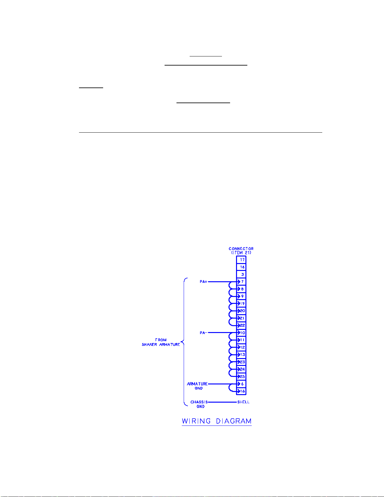
CONNECTOR PINOUT
TABLE 1
Shaker Control, DB25 Plug
Pin Description (NU = not used) Pin Description (NU = not used)
1NU 14 NU
2NU 15 NU
3NU 16 NU
4NU 17 NU
5NU 18 Armature ground
6Armature ground 19 PA Out+
7PA Out+ 20 PA Out+
8PA Out+ 21 PA Out+
9PA Out+ 22 PA Out+
10 PA Out-23 PA Out-
11 PA Out-24 PA Out-
12 PA Out-25 PA Out-
13 PA Out-
DIAGRAM 1

ENDEVCO 2911
INSTRUCTION MANUAL
IM2911
Page 7-2
2.DRAWINGS
FIGURE 1 –OUTLINE DRAWING
ENDEVCO 2911
INSTRUCTION MANUAL
IM2911
Page 7-3
FIGURE 2 –TOP VIEW
FIGURE 3 –SIDE VIEW OF STATOR REMOVED

ENDEVCO 2911
INSTRUCTION MANUAL
IM2911
Page 7-4
FIGURE 4 –BASE AFTER STATOR REMOVED
2911 max G levels
0
5
10
15
20
25
30
35
40
45
10 100 1000 10000 100000
Freq
g's attained
111 grams
17 grams
Table of contents


