CTC Union EcoComfort Manual

Providing sustainable energy solutions worldwide
162 305 54-1 2019-11–12
Installation and Maintenance Manual
CTC EcoComfort
Passive cooling unit
IMPORTANT
READ CAREFULLY BEFORE USE
KEEP FOR FUTURE REFERENCE


Installation and Maintenance Manual
CTC EcoComfort
Passive cooling unit
162 305 54-1 2019-11–12

4CTC EcoComfort
Table of contents
Congratulation on buying your new product! ___________ 5
Safety instructions _____________________________ 6
Check list ______________________________________________________________________ 7
The check list must be completed by the installer.__________7
Pipe installation __________________________________________________________7
Electrical installation____________________________________________________7
Customer information (adapted to the relevant installation)7
1. Installation______________________________________________________________ 8
1.1 Scope of delivery _______________________________________________8
1.2 Important to remember!______________________________________8
1.3 Technical data____________________________________________________9
1.4 Dimensional drawing __________________________________________9
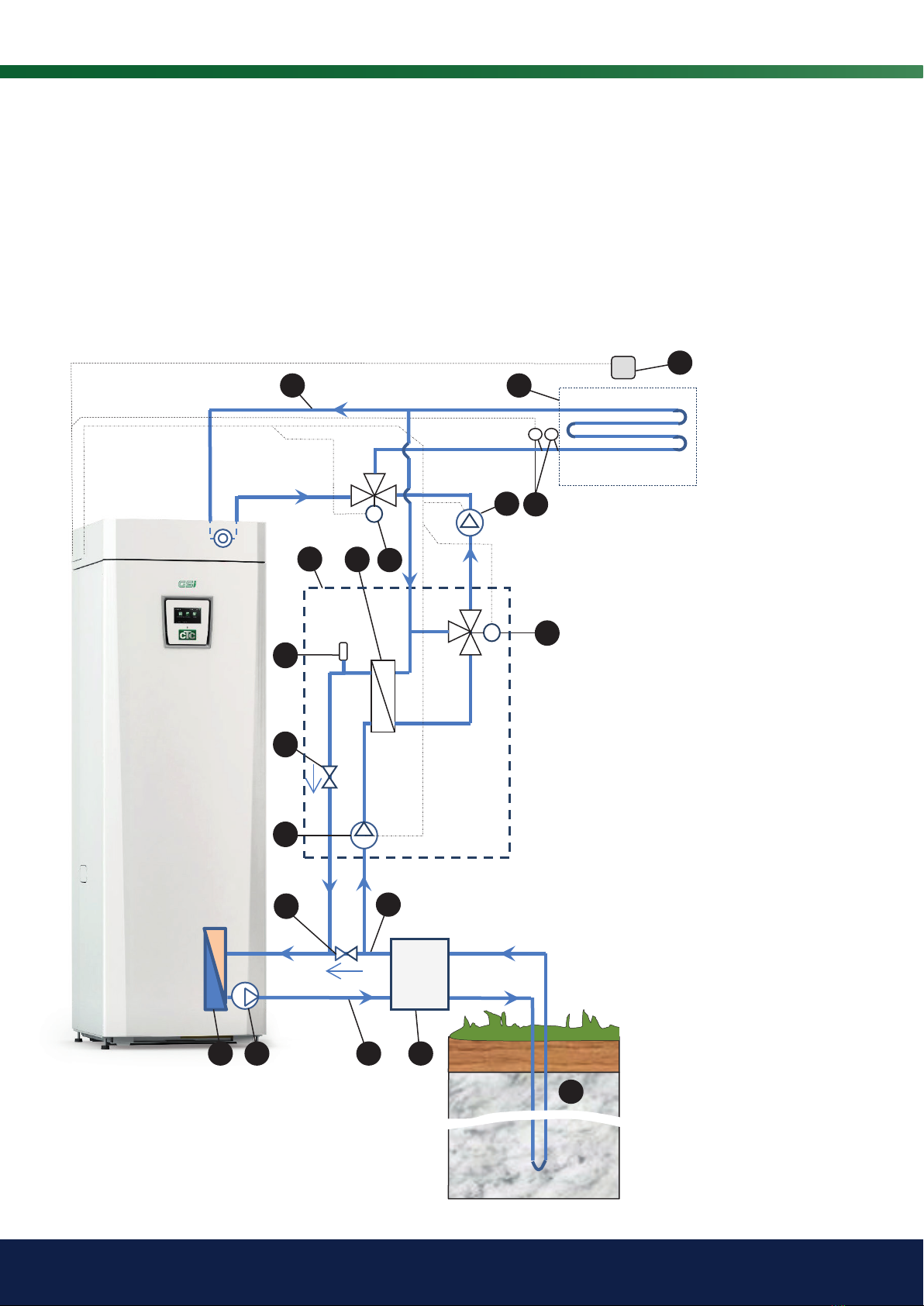
2. Schematic diagrams___________________________________________ 10
2.1 Alt. 1. Connection to the CTC controlling product,
common underfloor heating/cooling ___________________ 10
2.2 Alt. 2. Connection to the CTC controlling product,
underfloor/radiator heating and separate cooling coil
units _______________________________________________________________11
2.3 Component location_________________________________________12
3. Pipe installation___________________________________________________ 13
3.1 General___________________________________________________________13
3.2 Mounting_________________________________________________________13
3.3 Water quality, cold side _____________________________________13
3.4 Water quality, hot side_______________________________________ 13
3.5 Delivery inspection ___________________________________________13
3.6 General comment on pipe installation_________________ 13
3.7 Connection to the heating system______________________13
3.8 Connecting the diverting valve (Y60)___________________14
3.9 Non-return valve, cooling circuit_________________________15
3.10 Non-return valves, main circuit’s brine system _____15
3.11 Bleeding the cooling unit___________________________________ 15
3.12 Connection to the brine system _________________________15
3.13 Insulating the pipes __________________________________________15
3.14 Pressure drop curves for CTC EcoComfort _________16
4. Electrical connection __________________________________________ 17
4.1 Alt. 1. Connection to CTC controlling product, com-
mon underfloor heating/cooling _________________________18
4.2 Alt. 2. Connection to CTC controlling product, un-
derfloor/radiator heating and separate cooling coil
units _______________________________________________________________18
5. First start______________________________________________________________ 19
5.1 After installation _______________________________________________ 19
5.2 Start-up __________________________________________________________19
5.3 Selecting cooling function _________________________________ 19
5.4 Selecting system type/Menu settings _________________ 19
5.5 Bleeding and function test_________________________________ 19
6. Operation and maintenance ______________________________ 20
6.1 After installation _______________________________________________ 20
6.2 Periodic maintenance _______________________________________20
6.3 Breaks in operation __________________________________________ 20
6.4 Function description_________________________________________20
6.5 Function options _____________________________________________21
7. Troubleshooting and remedial action _______________ 23
7.1 Capacity data __________________________________________________24
For your own reference
Fill in the information below. It may come in useful if anything should happen.
Product: Manufacturing number:
Installer: Name:
Date: Tel. no.:
Electrical installer: Name:
Date: Tel. no.:
Enertech AB provides the information with reservation for any printing errors and subject to modification.

5CTC EcoComfort
Congratulation on buying your new product!
You have just bought a CTC EcoComfort passive
cooling unit, an accessory to the CTC controlling
product.
CTCEcoComfort is an accessory that utilises the cold in
the bore hole to cool your house during the summer. By
connecting CTCEcoComfort to the house’s underfloor
heating system (or separate fan coil units), its water
is cooled by the bedrock’s cooler collector water. The
heat in the house is taken out into the bore hole in the
bedrock.
The unit is completely pre-wired at the factory and easy
to connect to the system.
The cooling function is controlled entirely from
your controlling product on which you can set your
preferences for when and how you would like cooling.
This type of cooling is energy efficient – only circulation
pumps circulate the cool water. The capacity is,
however, slightly lower compared to so-called active
cooling where the more energy-intensive compressor
works to create coldness.
The system can be connected to underfloor heating or
separate fan coil units.
Connection to an underfloor heating system (underfloor
cooling) limits the temperature of the water circulating
in the heating system. A temperature that is too cold
can lead to condensation forming and result in serious
damage. The current room temperature should also be
considered.
Connection to separate fan coil units where the system
is insulated against condensation and condensation
collects in the fan coil unit can permit very low
temperatures.
The unit’s cooling capacity is dependent on several
factors such as the flows and the temperature of
the bore hole and house. The unit’s capacity is at its
greatest in the first part of summer, when the bore hole
is still cold after the winter’s heat extraction.

6CTC EcoComfort
Safety instructions
Turn off the power with an omnipolar switch before doing any work on the product.
The product must be connected to protective earth.
The product is classified as IP X1. The product must not be rinsed with water.
Never jeopardise safety by removing bolted covers, hoods or similar.
The product’s electrical systems should only be installed and serviced by a qualified
electrician.
-If the supply cord is damaged, it must be replaced by the manufacturer, its service
agent or similarly qualified persons in order to avoid a hazard.
This device can be used by children from the age of eight years and above and by
people with reduced physical, sensory or mental ability or lack of experience or
knowledge if they have been taught, either with supervision or with the instructions
provided, how to use the device safely and understand the risks involved. Children
should not play with the device. Cleaning and maintenance should not be carried
out by children without supervision.
If these instructions are not followed when installing, operating and maintaining the
system, Enertech’s commitment under the applicable warranty terms is not binding.

7CTC EcoComfort
Check list
The check list must be completed by the installer.
• In the event of a service, this information may be called for.
• Installation shall always be done according to the Installation and maintenance manual.
• Installation shall always be carried out in a professional manner.
• Following installation, the unit shall be inspected and checked for functionality.
The points below shall be checked off.
Pipe installation
The system has been filled, positioned and adjusted in the correct manner according to the
instructions.
The products are positioned so that they can be serviced.
Pumps, valves, etc. are dimensioned for the required flows.
The unit has been tested for leaks and tightness.
Bleeding performed (re-bleeding may be necessary).
Electrical installation
Proper wiring, performed according to current regulations.
Correct connection to the controlling product.
Customer information (adapted to the relevant installation)
Start-up with customer/installer.
Review of the cooling unit’s function.
Installation and maintenance manual supplied to the customer.
Check and filling, system.
Information on fine adjustments, settings, etc.
Information on potential operational malfunction and remedial action.
Guarantees and insurance.
Information and procedure for fault registration.

8CTC EcoComfort
1. Installation
1.1 Scope of delivery
The following items are included in the delivery of a CTC EcoComfort passive
cooling unit:
• Packaging box with impact protection
• Cooling unit fitted in enclosed box containing:
–Heat exchanger
–Circulation pump (circulates brine in the collectors)
–Mixing valve with mounted steering motor, including 2 m connection
cable
–Non-return valve
–Bleeding valve for the cold side (brine)
–Support sleeves in copper pipe connections
• Non-return valve for main brine system
• Installation and Maintenance Manual
1.2 Important to remember!
Check the following points in particular at the time of delivery and installation:
• Check before installation that the product has not been damaged in
transit. Report any transportation damage to the carrier.
• Make sure the heating system is suitable for cooling, and the type of
system (underfloor heating, fan coil units).
• Make sure the product is mounted horizontally.
• Make sure the wall is suitable for installation, and no hidden electrical
cables/pipes can be damaged during installation.
• Remember to leave a service area around the product.
• The radiator system’s water flow passes through the heat exchanger
in CTCEcoComfort. This is why the radiator system must be flushed
thoroughly before installation.
• The packaging must be deposited at a recycling station or with the
installation engineer for correct waste management.
• Obsolete products must be disposed of correctly and transported to a
waste station or distributor/retailer offering this service. Disposal of the
product as household waste is not permitted.

9CTC EcoComfort
1.3 Technical data
1.4 Dimensional drawing
415
255
80 (2X)
220
227
70 (4X)
(7)
15
60
377
9090
UNLESS OTHERWISE SPECIFIED
DIMENSIONS ARE IN MILLIMETERS
± 1
Cooling Unit
WEIGHT:
A1
SHEET 1 OF 2
SCALE:1:1
DWG NO.
TITLE:
REVISION
DO NOT SCALE DRAWING
MATERIAL:
DATE
SIGNATURE
NAME
DEBUR AND
BREAK SHARP
EDGES
FINISH:
UNLESS OTHERWISE SPECIFIED:
DIMENSIONS ARE IN MILLIMETERS
SURFACE FINISH:
TOLERANCES:
LINEAR:
ANGULAR:
Q.A
MFG
APPV'D
CHK'D
DRAWN
CTC EcoComfort passive cooling unit
Electrical data (components powered by the
CTC controlling product)
230V 1N~ 50Hz Approx. 2x2.5 m cable
from cooling unit
included for connection
to the controlling
product
IP class IP X1
Nominal power output kW 0.03
Volume (V) cold/hot side l 0.46/0.54
Max. operating pressure (PS) kPa/Bar 1/10
Min./max. operating temperature (TS) ºC +2/80
Weight excl. packaging (net) kg 11
Weight incl. packaging kg 12.5
Dimensions incl. packaging (DxWxH) mm 310x280x580
Basic dimensions excl. packaging (DxWxH) mm 220x255x410
Height incl. connections mm 470
Pipe connections (4 pcs) mm Ø22 Copper
Capacity See separate section
Non-return/throttle valve, main brine system Rp 1" Internal thread

10 CTC EcoComfort
2. Schematic diagrams
2.1 Alt. 1. Connection to the CTC controlling
product, common underfloor heating/cooling
The diagram shows schematically how CTCEcoComfort is connected to the systems; additional
equipment, such as expansion vessels, shut-off valves, safety valves, buffer tank etc., is not shown
here. The controlling product in this example is the ground source heat pump CTC GSi. In this
example (Alt.1), the diverting valve Y60 is connected to the combined heating/cooling circuit as well
as to the controlling product and CTC EcoComfort. The diverting valve is controlled by the controlling
product.
Circuit 1, combined
heating/cooling
M
2
4
5
6
1
3
7
8
10
11
12
13
15
16
17
18
20
M
19
9
Y60
Controlling
product 1. CTCEcoComfort passive cooling
unit
2. Heat exchanger
3. Bleeding valve
4. Mixing valve with motor
5. Non-return valve, cooling unit
6. Built-in circulation pump
7. Evaporation heat exchanger in the
controlling product
8. Brine pump in the controlling
product
9. Non-return/throttle valve, main
system
10. Filling equipment
11. Bore hole with collectors
12. Circulation pump
13. Primary flow sensor
14. Outgoing pipe from the controlling
product
15. Return pipe from heating system
16. To bore hole
17. From bore hole
18. Heating system
19. Diverting valve
20. Room sensor

11CTC EcoComfort
The diagram shows schematically how CTCEcoComfort is connected to the systems; additional
equipment, such as expansion vessels, shut-off valves, safety valves, buffer tank etc., is not
shown here. The controlling product in this example is the ground source heat pump CTC GSi.
2.2 Alt. 2. Connection to the CTC controlling product,
underfloor/radiator heating and separate cooling coil units
Controlling
product
M
2
4
5
6
1
3
7
8
10
11
12
13
14
15
16
17
18
19
20
20
9
B2
Circuit 1,
heating only
Circuit 2,
cooling only
1. CTCEcoComfort passive cooling
unit
2. Heat exchanger
3. Bleeding valve
4. Mixing valve with motor
5. Non-return valve, cooling unit
6. Built-in circulation pump
7. Evaporation heat exchanger in the
controlling product
8. Brine pump in the controlling
product
9. Non-return/throttle valve, main
system
10. Filling equipment
11. Bore hole with collectors
12. Circulation pump
13. Primary flow sensor
14. Outgoing pipe from the controlling
product
15. Return pipe from heating system
16. To bore hole
17. From bore hole
18. Heating system
19. Fan coil unit with condensation
collector
20. Room sensor

12 CTC EcoComfort
A. Connection water flow in.
B. Connection water flow out (cooled water).
C. Incoming connection from bedrock collector
D. Outgoing connection to bedrock collector
1. Box with lid, tight design
2. Cold side, brine system
3. Hot side, heating system
4. Heat exchanger
5. Mixing valve with motor for cooling control
6. Circulation pump, bore hole circulation
7. Bleeder, cold side (brine)
8. Non-return valve, cooling unit (in the pipe)
9. Cables for connection to the controlling product
(2.5 m)
10. Non-return/throttle valve, main system (brine),
provided
11. Block for manual control
2.3 Component location
A
C
B
D
11
10
2
3
4
9
5
6
8
1
7

13CTC EcoComfort
3. Pipe installation
3.1 General
This chapter is intended for anyone responsible for the installation. Take
your time going through functions and settings with the property owner
and answer any questions. Installation must be performed by a qualified
professional.
3.2 Mounting
CTCEcoComfort must be mounted on the wall with the wall bracket
provided. Fasten the bracket with suitable screws (not included) for the type
of wall material. Make sure the bracket is screwed securely in a horizontal
position. Then hang the box on the bracket and secure with a screw in
the mounting ear underneath the box. For offset dimensions, see sections
Dimensional drawing and
Technical data
.
3.3 Water quality, cold side
Approved antifreeze liquids are propylene/ethylene glycol and ethyl alcohol
with max. 30% concentration by volume. The suitability of other antifreeze
liquids can be considered after checking the materials used in constituent
components. Note that the unit capacity is specified for ethyl alcohol which
is 30% by volume.
3.4 Water quality, hot side
The radiator system’s water flow passes through the heat exchanger
in CTCEcoComfort. This is why the radiator system must be flushed
thoroughly before installation. If dirt is to be expected, the installation of a dirt
filter before EcoComfort is recommended.
3.5 Delivery inspection
Check that the product has not been damaged in transit. Report any
transportation damage to the carrier. Check that the delivery is complete.
3.6 General comment on pipe
installation
The installation must be carried out in accordance with current standards
and regulations.
3.7 Connection to the heating system
The outgoing water (cooled water) from EcoComfort is connected to a fan
coil unit or to the heating/cooling system via a diverting valve (Y60). See
chapters
Schematic diagrams
and
Connecting the diverting valve (Y60)
. The
cooling flow back to EcoComfort should be connected to the heating/cooling
system’s return line.
In cases where one or more fan coil units are connected, it is the return
water from the fan coil system that is connected to the cooling unit’s
incoming pipe. Note that the cooling unit does not contain a circulation
pump for the hot side; this must be dimensioned and connected separately.

14 CTC EcoComfort
3.8 Connecting the diverting valve (Y60)
Connect the divering valve according to the instruction below. The diverting valve must be part of the installation
showed in Alt.1
(common underfloor heating/cooling
).
Groove in shaft coupling
Diverting valve
Down
Up
The mixing valve motor is mounted on the
valve with the knob in the centre position.
A
AB
B
When the motor transfers power to the black wire, port A opens
and port B closes.
Flow AB to A = hot water production and Black is powered.
NB: The valve must be “turned round” in order to change
direction.The valve must always be fitted so that the flow can
move freely.
Diverting valve ESBE VRG 230/Ara 635
The valve can be mounted inversely, right to left, left to right.
The direction of the motor can be changed using the loop under the actuator cap.
The loop is always connected towards the heat pump.
Diverting valve LK EMV 110-K
Knob
Actuator

15CTC EcoComfort
3.9 Non-return valve, cooling circuit
A non-return valve is pre-installed in the unit at the factory to prevent a short-
circuiting flow when the cooling pump is stationary.
3.10 Non-return valves, main circuit’s
brine system
The delivery includes a non-return/throttle valve (int. 1” thread) which must
be mounted in the brine system’s main flow between the heat pump and
cooling unit; see schematic diagram for connection. Make sure the valve is
installed with the correct flow direction; see the marking on the valve. The
valve prevents a short-circuiting flow when the heat pump’s brine pump is
stationary.
3.11 Bleeding the cooling unit
A manual bleeding valve is mounted in the cooling unit on the cold side’s
highest point. The valve is not designed to bleed the entire cold side system,
but only to bleed the parts of the exchanger system. Ensure that liquid drawn
out is collected and disposed of. Re-bleeding/checks may be needed after a
few days.
3.12 Connection to the brine system
The cooling unit is connected to the incoming and outgoing collector pipes
for the bore hole. The cooling unit’s incoming fluid connection is connected
to the brine pipe coming from the bore hole while its outgoing fluid
connection is connected to the brine pipe that goes to the bore hole. Do not
forget to install the non-return valve in the main brine circuit.
3.13 Insulating the pipes
The brine pipes must be insulated against condensation right up to and
tightly against the cooling unit’s box. Use insulation that is intended for
protection against condensation.
The pipes of the heating system must be insulated with thermal insulation.

16 CTC EcoComfort
Pump capacity Grundfos Alpha 2 15-60
Pressure increase, brine side (cold side)
Including pipe and non-return valve.
Pressure drop, radiator side (hot side)
Including pipe and mixing valve.
Tryckfallradiatorsidan
Tryckökningbrinesidan
0
5
10
15
20
25
30
35
40
0 0,25 0,5 0,75 1 1,25 1,5 1,75 2 2,25
Tryckfall,∆p(kPa)
Flöde,Q(m³/h)
0
5
10
15
20
25
30
35
40
0 0,2 0,4 0,6 0,8 1 1,2 1,4
Tryckökning,∆p(kPa)
Flöde,Q(m³/h)
Tryckfallradiatorsidan
Tryckökningbrinesidan
0
5
10
15
20
25
30
35
40
0 0,25 0,5 0,75 1 1,25 1,5 1,75 2 2,25
Tryckfall,∆p(kPa)
Flöde,Q(m³/h)
0
5
10
15
20
25
30
35
40
0 0,2 0,4 0,6 0,8 1 1,2 1,4
Tryckökning,∆p(kPa)
Flöde,Q(m³/h)
Pressure drop, ∆p (kPa)Pressure increase, ∆p (kPa)
Flow, Q (m3/h
Flow, Q (m3/h
3.14 Pressure drop curves for CTC EcoComfort

17CTC EcoComfort
4. Electrical connection
Installation, switching and any servicing of the product’s electrical
attachments must be performed by a qualified electrician. All wiring must be
done according to current regulations.
All cooling control takes place from the control system in the CTC controlling
product.
The radiator pump, mixing valve motor and sensors of the CTC EcoComfort
as well as the diverting valve (Y60) (in case of common underfloor heating/
cooling), must be connected to the corresponding block in the controlling
product. See also chapter
Electrical Installation
in the controlling product’s
manual.
Electrical components
The figures below show designation and placement of the electrical
components in CTCEcoComfort (left) and the
common heating/cooling
circuit (right).
1
1
60
From the controlling
product

18 CTC EcoComfort
Component
Designation,
component
Block in
controlling
product Cable Note
Radiator pump 1,
used for both heating
and cooling
G1 A31
A33
PE
L1
Neutral
Earth
230V 1N~
(Not mounted in
CTCEcoComfort)
Radiator pump 2,
cooling pump in
CTCEcoComfort
G2, G3* A36
A34
PE
L1
Neutral
Earth
230V 1N~
Mixing valve in
CTCEcoComfort
Y2, Y3* A15
A16
A17
Open signal (white 3)
Close signal (brown 1)
Neutral (blue 2)
230V 1N~
Fully open = 10 (cooling)
Fully closed = 0 (no cooling)
Diverting valve Y60 A36
A25
A26
Relay output
Phase
Neutral
230V 1N~
Fully open= cooling
Fully closed= no cooling
Primary ow sensor 1 B1 G13
G14
Pole-independent
Pole-independent
Extra low voltage protection
Primary ow sensor 2 B2 G15
G16
Pole-independent
Pole-independent
Extra low voltage protection
Room sensor B11 G17
G18
G19
RG-1 (block in the room sensor)
RG-2 (block in the room sensor)
RG-4 (block in the room sensor)
Extra low voltage protection
Component
Designation,
component
Block in
controlling
product Cable Note
Radiator pump 1,
for the heating system
G1 A31
A33
PE
L1
Neutral
Earth
230V 1N~
(Not mounted in
CTCEcoComfort)
Radiator pump 2,
cooling pump in
CTCEcoComfort
G2, G3* A36
A34
PE
L1
Neutral
Earth
230V 1N~
Mixing valve in
CTCEcoComfort
Y2, Y3* A15
A16
A17
Open signal (white 3)
Close signal (brown 1)
Neutral (blue 2)
230V 1N~
Fully open = 10 (cooling)
Fully closed = 0 (no cooling)
Primary ow sensor 1,
for the heating circuit
B1 G13
G14
Pole-independent
Pole-independent
Extra low voltage protection
Primary ow sensor 2,
for the cooling circuit
B2 G15
G16
Pole-independent
Pole-independent
Extra low voltage protection
Room sensor 1,
for the heating circuit
B11 G17
G18
G19
RG-1 (block in the room sensor)
RG-2 (block in the room sensor)
RG-4 (block in the room sensor)
Extra low voltage protection
Room sensor 2,
for the cooling circuit
B12 G20
G21
G22
RG-1 (block in the room sensor)
RG-2 (block in the room sensor)
RG-4 (block in the room sensor)
Extra low voltage protection
4.1 Alt. 1. Connection to CTC controlling product,
common underfloor heating/cooling
4.2 Alt. 2. Connection to CTC controlling product, underfloor/
radiator heating and separate cooling coil units
* valid for EcoLogic Pro and EcoZenith i550 Pro

19CTC EcoComfort
5. First start
5.1 After installation
Check that:
1. All sensors have been mounted in the designated spaces.
2. All connections are properly installed, the systems are filled with liquid
and have been pressure tested and checked for tightness.
3. The system is pressurised and bled. Make extra sure that the heat
exchanger in CTCEcoComfort is bled; use the air valve in the unit.
Additional bleeding may be needed after start-up.
5.2 Start-up
Switch on the main switch for the CTC controlling product.
5.3 Selecting cooling function
The cooling function can now be selected in the controlling product’s menu
system. Go to the “Advanced/Define system/Cooling” menu and select
”Yes”.
5.4 Selecting system type/Menu
settings
For menu settings, see the Installation & Maintenance Manual for the
controlling product.
5.5 Bleeding and function test
Additional bleeding can now be performed by manually activating the
pump and mixing valve in the controlling product (the mixing valve in
CTCEcoComfort also has a “manual mode”). Push in and twist as shown in
the picture to release the mixing valve knob.
After activating the cooling function in the controlling product, check the
following by going to the “Advanced/Service/Function test” menu on the
controlling product:
• The pump in CTCEcoComfort receives power when activated.
• The mixing valve closes (moves towards zero) when the “reduce” signal
is activated.
• The mixing valve opens (moves towards 10) when the “increase signal”
is activated.
Disengaging the mixing valve for
manual mode.
!For menu settings,
see the Installation &
Maintenance Manu-
al for the controlling
product.

20 CTC EcoComfort
M
6. Operation and
maintenance
6.1 After installation
Once the system has been installed, the user and installer must together check
that the system is in perfect working order. Let the installer show you where the
power switches, controls, valves, safety valves, etc. are so that you know how
the system works and how it should be maintained.
The system may need to be re-bled after a few days of operation. Also check for
any leakage after a few days of operation; re-tighten if necessary.
6.2 Periodic maintenance
CTC EcoComfort does not normally require any special maintenance, although it
should be checked for leakage and residual air:
• Immediately after installation and pressurisation of the systems.
• After a week of operation.
• After about a month of operation, then each year (leakage).
6.3 Breaks in operation
If the unit is to be turned off for a period of time, ensure the following:
• The taps, valves, etc. are closed/set to a position that means the system
cannot be damaged during this period.
• The whole system is drained of water (the cold side does not need to be
drained since it is protected against frost). Make sure that electrical power
is cut off to pumps etc.
• Safety valves and other functions are checked when the system is
restarted.
• When draining, make sure all water is drained from the heat exchanger;
remove one of the lower connections.
6.4 Function description
Passive cooling
Passive cooling means that the free cooling available is made use of. In this
case, the bore hole’s cool temperature cools the radiator water. The compressor
in the heat pump is not used; only pump energy is required to circulate the
water.
Table of contents
Other CTC Union Accessories manuals
Popular Accessories manuals by other brands

Datalogic
Datalogic S51-MA Series instruction manual

SImx
SImx LHT0120 installation manual

Alnor
Alnor HRQ-PremAIR-SENS-CO2 user manual

Dixon Bayco
Dixon Bayco FT394 Maintenance & Operating Instructions

rollease acmeda
rollease acmeda AUTOMATE manual

Sulzer
Sulzer XJ Series Assembly and installation instruction